
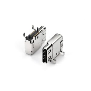
USB4 Cable Specifications: The Future of High-Speed Connectivity
Introduction As technology continues to evolve, the demand for faster, more efficient connectivity solutions has become critical for businesses and

The cable eye diagram is a graphical representation of the electric field around an energized cable. It is used to help visualize and troubleshoot high-frequency problems. The diagram shows the distribution of the electric field in the radial, tangential, and axial directions. It can help identify problems with the insulation, conductor, or groundings. This information can help to prevent or fix these problems, which can improve the performance of the cable at high frequencies.
The cable eye diagram is used to test cables for high-frequency performance by evaluating the distribution of the electric field in the radial, tangential, and axial directions. This information can help identify problems that could affect the performance of the cable at high frequencies. Some common problems that can be identified using the cable eye diagram include:
-Insulation failure
-Conductor breakdown
-Grounding issues
-Capacitive coupling
The test setup for creating a cable eye diagram requires a high-frequency generator, a probe, and an oscilloscope. The probe is inserted into the cable, and the high-frequency generator is used to send a signal through the cable. The oscilloscope is used to measure the response of the cable.
The cable eye diagram is a graphical representation of the signal that is transmitted through the cable. The upper part of the diagram shows the signal as it is received by the probe, and the lower part of the diagram shows the signal as it is transmitted by the probe. The width of the lines in the diagram represents the amplitude of the signal. The shape of the lines in the diagram can be used to identify problems with the cable.
The cable eye diagram can be used to optimize the performance of a high-frequency cable. By identifying the problems with the cable, you can make changes to the design of the cable that will help to improve its transmitter performance. The cable eye diagram can also be used to verify the performance of a high-frequency cable after it has been manufactured.
The high-frequency performance of a cable is affected by many factors, including the:
The type of insulation affects high-frequency performance of a cable by influencing the distribution of the electric field. Some types of insulation are better at preventing the electric field from spreading than others. This can help to improve the high-frequency performance of the cable.
The thicker the insulation, the better it will be at preventing the electric field from spreading. This can help to improve the high-frequency performance of the cable.
Larger conductors are able to carry more current and therefore have a higher bandwidth capacity. This can help to improve the high-frequency performance of the cable.
The distance between conductors also affects high-frequency performance. The closer the conductors are together, the greater the capacitive coupling will be. This can lead to problems with the high-frequency performance of the cable.
Cables with a twisted-pair geometry are better able to handle high frequencies than cables with a parallel geometry. This is because the twisting of the pairs helps to reduce the capacitive coupling between the conductors.
A good ground connection will help to ensure that any noise or interference is eliminated, which can improve the high frequency performance of the cable.
Environmental conditions can also affect high frequency performance. Factors such as temperature, humidity, and electromagnetic interference can all interfere with the signal quality and cause problems with the high frequency performance of the cable.
The material of the conductor also affects high frequency performance. Some materials are better than others at handling high frequencies. This can help to improve the high frequency performance of the cable.
-Choose a cable with good insulation to prevent the electric field from spreading.
-Choose a cable with a large conductor size to increase the bandwidth capacity.
-Choose a cable with a twisted-pair geometry to reduce capacitive coupling between conductors.
-Make sure that the quality of the ground connection is good so that any noise or interference is eliminated.
-Ensure that the environmental conditions are within the acceptable range for your application.
-Choose a conductor material that is good at handling high frequencies.
To ensure that your cables meet all your high-frequency requirements, you should:
-Choose the right cable for the application
-Ensure that the insulation is adequate
-Make sure that the conductor is properly shaped
-Make sure that the distance between the conductor and ground is appropriate
-Use a good ground connection
-Check for capacitive coupling.
When looking at a cable eye diagram, there are a few key things to look for to determine the quality of the signal.
If the shape of the eye is distorted or asymmetrical, then the signal is likely not being transmitted accurately.
If the width of the eye is too narrow, then it means there is not enough bandwidth available to support high-frequency signals.
The height of the eye can be used to gauge how much noise is present in the signal. A high-frequency signal will have a taller eye than a low-frequency signal.
By looking at all of these factors, you can get a good idea of the quality of the signal and whether it is suitable for use in high-frequency applications.
Impedance mismatch can occur when the impedance of the transmitter and receiver are not the same. When this happens, energy is reflected back and forth between the transmitter and receiver, which can distort signal integrity. Reflections can also occur when there is a discontinuity in the transmission line. This can be caused by a faulty connection or an object that interrupts the transmission path.
Reflections can cause problems for high-frequency signals because they create echoes of the original signal. This can distort the signal and lead to interference and crosstalk. In some cases, reflections can even cancel out the original signal, leading to a total loss of signal.
When designing a system that relies on high-frequency signals, it’s important to understand the relationship between the cable eye diagram and high-frequency signals. By understanding how reflections and impedance mismatches can affect your signal, you can take steps to minimize their impact on your system. Here are some tips for reducing reflections in your cable assembly:
– Use impedance matched cables and connectors
– Minimize the length of the cable
– Keep the cable as straight as possible
– Use shielding to protect against electromagnetic interference
– Use quality components to ensure accurate signal transmission

Crosstalk can cause high frequency signals to be distorted, which can lead to a high bit error rate. Apart from bit errors, crosstalk can also cause a signal to completely disappear. Crosstalk is caused by the magnetic fields created by adjacent wires in a cable. These fields can cause intersymbol interference and distort the signals passing through them. This interference becomes more pronounced at higher frequencies, which is why it is important to use cables that are designed for high frequency signals when transmitting or receiving them.
Crosstalk can be a major issue when working with high frequency signals, which is why it is important to take steps to reduce it as much as possible. There are several things you can do to reduce crosstalk in your cables. One is to use twisted-pair wiring, which helps to keep the magnetic fields created by adjacent wires aligned. You can also use shielding to protect the signals from interference. And finally, you can use high-quality cables that are designed for high frequencies.
Here are some examples of good and bad cable assemblies, as seen by the eye diagram.
The good cable assembly has a clear, symmetrical eye pattern with a clear rising edge and falling edges with no reflections or distortion. This indicates that the signal has been transmitted accurately in the signal path and without interference.
The bad cable assembly shows signs of reflection and distortion. This can be caused by impedance mismatches, reflections, or other signal impairments. This can cause problems for high-speed digital signals, leading to attenuation, distortion, and signal loss.

When creating a cable eye diagram, there are a few key things to keep in mind.
The first is that the diagram should be as simple as possible so that it’s easy to understand.
The second is that the cables should be clearly labeled so that there is no confusion about which cable goes where.
Finally, the eye diagram should be arranged in a way that makes sense, with the most important cables at the top.
Several best practices can be followed to maintain healthy cables for high data rate transmission. Firstly, it is important to use high-quality cables that are designed for carrying high frequency signals. Such cables can only be supplied by quality manufacturers such as Edom Electronics. In addition to this, care should be taken when routing cables near high frequency components or circuits, as even a small amount of crosstalk can degrade the performance of the system. Cable ties and clips should also be used to secure cables in place, and keep any excess cable length to a minimum. Finally, regularly checking cable connections and ensuring that all cables are properly terminated will help to maintain a good signal-to-noise ratio. By following these tips, you can help to ensure the best possible performance from your system.
Introduction As technology continues to evolve, the demand for faster, more efficient connectivity solutions has become critical for businesses and
Understanding the Evolution of USB Connectors In today’s technology-driven world, USB (Universal Serial Bus) connectors are an integral part of
At EDOM Electronics, we take pride in our meticulous approach to manufacturing high-quality USB C to C cables. Today, we’re
