You've probably searched "standard M12 connector" expecting a simple answer. But if you've ever received the wrong cable or faced a compatibility issue on-site, you already know the truth: there's no single "standard" M12.
A standard M12 circular connector refers to a mechanical thread specification (12mm diameter), not a single electrical product. The actual "standard" is a family of connectors with different coding keying—A, B, D, X, K, L, S, or T-code—each preventing cross-connection between incompatible electrical protocols. Selecting the right M12 means matching both pin count and code to your application's protocol requirements.

I handle customer inquiries daily, and the most common issue I see is ordering "M12 connector" without specifying which code. This assumption that M12 is universal leads to returns, project delays, and frustration. Let me walk you through what "standard" actually means in M12 terminology.
Why isn't there one standard M12 connector type?
When customers first contact us for M12 connectors, many assume all M12s work the same way. The confusion is understandable—the "M12" designation sounds like a product model number.
The M12 designation only describes the mechanical thread diameter (12mm), not the electrical configuration. The IEC 61076-2-101 standard defines M12 as a connector family with multiple coding variants1, each designed for specific protocol requirements and mechanically keyed to prevent accidental cross-mating between incompatible systems.

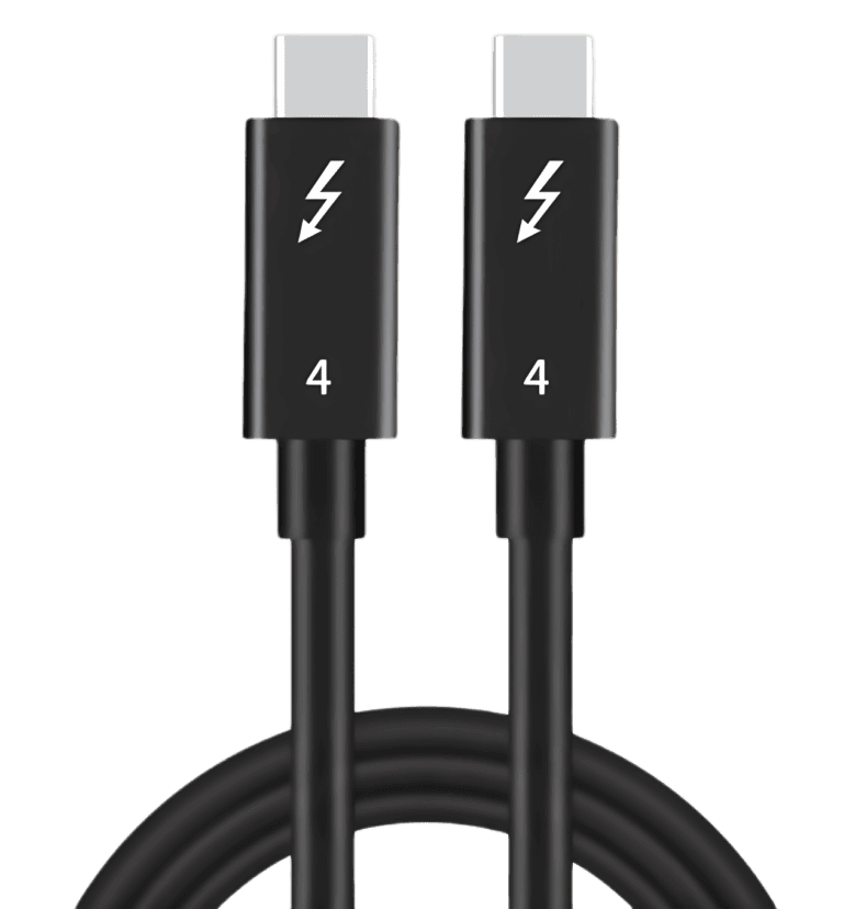
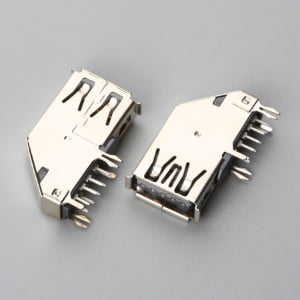
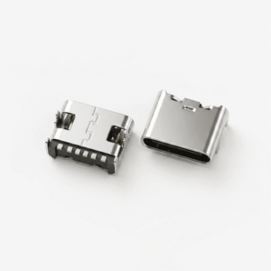
Think of M12 like USB connectors. USB-A, USB-C, and Micro-USB all fall under "USB standard," but you can't plug a USB-C cable into a USB-A port. M12 works the same way—the coding key physically prevents you from connecting an A-code plug to a D-code receptacle, even though both have 12mm threads.
When we receive a request for "standard M12 connectors," our first response is always: "What's your application?" Because the real selection isn't just about pin count—it's about protocol compatibility. A 4-pin A-code connector serves completely different purposes than a 4-pin D-code connector. The mechanical keying exists precisely because voltage, signal speed, and shielding requirements differ drastically between industrial sensor circuits and Ethernet networks.
We've processed countless re-orders where customers discovered their A-code and D-code cables aren't interchangeable after receiving the shipment. The coding keyway—that small notch or protrusion on the connector body—is the most critical quality checkpoint in our production process. It's not decorative; it's the physical enforcement of electrical incompatibility protection.
| M12 Code | Typical Pin Counts | Common Protocol Applications | Physical Keying Position |
|---|---|---|---|
| A-code | 3, 4, 5, 8 pins | DC power, discrete I/O, fieldbus | 12 o'clock notch |
| B-code | 3, 4, 5 pins | Profibus DP, older fieldbus | 60° offset keyway |
| D-code | 4 pins | 100 Mbps Ethernet, PROFINET | 180° from A-code |
| X-code | 8 pins | Gigabit Ethernet, high-speed data | Cross-pattern keys |
The table above shows why "standard" is misleading. Each code represents a different physical and electrical architecture. Distributors sometimes confuse the 12mm thread specification with electrical compatibility, assuming any M12 cable fits any M12 device. This mechanical-electrical disconnect is the root cause of most specification errors I encounter.
Which M12 coding do I actually need for my application?
After explaining that M12 isn't a single product, the next question I hear is always: "So which code should I order?" This is where application context becomes critical.
The M12 coding you need depends on the communication protocol and power requirements of your connected devices. A-code dominates sensor and actuator power connections; D-code and X-code are typically specified for Ethernet-based industrial networks; B-code serves legacy Profibus systems2. Coding selection must match the device manufacturer's specification—codes are not interchangeable alternatives.

Let me share a common scenario from our quotation process. A customer requests "M12 connectors for factory sensors." Without further details, I can't quote accurately because:
- If they're connecting simple proximity sensors with DC power (10-30V), A-code is commonly used
- If they're integrating vision sensors with Gigabit Ethernet output, X-code is typically specified
- If they're retrofitting older equipment with Profibus communication, B-code is often required
The selection framework isn't about choosing the "best" code—it's about matching what the equipment manufacturer already specified. When we ask customers about their application, we're really asking: "What does the device datasheet say?" Because the device determines the coding requirement, not personal preference or availability.
I've seen distributors try to substitute D-code for A-code because "they both have 4 pins." This doesn't work. The pin assignments differ, the shielding requirements differ, and the voltage ratings differ. The coding key prevents the physical connection, but even if you force compatibility (which damages the connector), the electrical mismatch would cause system failures.
Here's the practical approach we recommend: Check the equipment datasheet first. Device manufacturers specify M12 coding in their connection diagrams. If the datasheet shows "M12 A-coded 4-pin male," that's your requirement—not "M12 4-pin" in general. The coding designation isn't optional information; it's part of the electrical specification.
How A-code became the de facto "default" M12
When customers say "standard M12," they usually mean A-code without realizing it. This code dominates industrial sensor and actuator applications, which is why it feels like the default.
A-code's prevalence comes from its suitability for DC power circuits (up to 63V, 4A per pin3) and discrete signal transmission commonly used in automation sensors—photoelectric sensors, inductive proximity sensors, pneumatic valve connections. The 3-pin, 4-pin, and 5-pin A-code variants cover most traditional fieldbus and I/O requirements. When automation equipment manufacturers design sensor interfaces, A-code is often their first consideration because it matches the voltage and current parameters of industrial control systems.
But dominance doesn't mean universality. A-code has bandwidth limitations that make it unsuitable for high-speed Ethernet. The conductor gauge and shielding structure in A-code cables are optimized for DC and low-frequency signals, not 100 Mbps or 1 Gbps data rates. This is why D-code and X-code exist—they're protocol-specific solutions, not simply "better versions" of A-code.
When D-code and X-code replace A-code
D-code and X-code emerged as Ethernet protocols entered factory floors. Traditional A-code couldn't support the signal integrity requirements of 100BASE-TX or 1000BASE-T communication.
D-code uses 4 pins in a shielded twisted-pair configuration, typically specified for 100 Mbps Ethernet connections4 in industrial automation—PROFINET, EtherNet/IP, EtherCAT applications5. The 180-degree coding offset from A-code ensures you can't accidentally plug a sensor power cable into an Ethernet port.
X-code employs 8 pins with dual shielded twisted pairs, commonly used for Gigabit Ethernet6 in machine vision systems, industrial PCs, or high-bandwidth sensor networks. The cross-pattern keying makes X-code physically distinct from all other M12 codes.
The key insight: D-code and X-code aren't upgrades you choose for "better performance." They're required when your equipment uses Ethernet protocols. If your device datasheet specifies X-code, you must use X-code—A-code simply won't transmit the signal correctly, even if you could physically connect it (which you can't, due to keying).
What happens when I order the wrong M12 code?
I want to share what typically happens when coding specifications go wrong, because understanding the consequences helps prevent the mistake.
Ordering the wrong M12 code results in physical incompatibility—the connector won't mate due to keying mismatch. Even if pin counts match, different codes have different keyway positions that prevent cross-connection. This causes project delays, return shipments, and potential equipment damage if users attempt forced mating.

The most common error pattern we see: Customer orders "M12 4-pin cable" without specifying code. We ask for clarification. Customer responds "4-pin is 4-pin, right?" We explain the coding requirement. Customer checks their equipment and discovers they need D-code, not the A-code they assumed.
This scenario repeats weekly in our inbox. The delay costs the customer lead time—2-3 weeks for re-ordering if we need to source different coding variants. The cost isn't just the return shipping; it's the project timeline impact when installers arrive on-site with incompatible cables.
But here's the dangerous scenario: attempting to "make it work" by modifying the keying. I've heard of technicians filing down coding keys or forcing mismatched connections. This bypasses the safety design. Even if you achieve physical connection, electrical mismatches can damage sensitive electronics—wrong voltage on data lines, incorrect impedance causing signal reflections, or shielding discontinuities creating EMI issues.
The coding system exists because industrial environments are harsh and connection mistakes are costly. A sensor cable accidentally plugged into an Ethernet port could introduce 24V DC into a 3.3V signal circuit. The mechanical keying is the first line of defense against these errors.
How to specify M12 correctly in your RFQ
Based on the clarification questions we ask repeatedly, here's what should be in every M12 connector request:
- Coding type: A, B, D, X, or other (not optional)
- Pin count: 3, 4, 5, 8 pins (within that code family)
- Connector gender: Male plug or female receptacle
- Mounting type: Panel mount, cable mount, PCB mount, or field-wireable
- Cable specifications: Shielded/unshielded, conductor gauge, cable length
- Application context: Sensor power, Ethernet, fieldbus (helps us verify coding choice)
When customers provide this information upfront, we can quote accurately and ship correctly the first time. When any piece is missing, we're guessing—and guessing leads to mismatches.
How do I identify the M12 code on existing connectors?
Sometimes you're not designing a new system—you're maintaining or expanding an existing installation and need to match what's already there.
M12 coding can be identified by the keying position on the connector face—a notch, protrusion, or pattern that differs by code. A-code has a single keyway at 12 o'clock; D-code's keyway is offset 180 degrees7; X-code has cross-pattern keys. Most manufacturers also print the code letter on the connector body or in device documentation.

If you have physical access to the connector, look at the mating face. The keyway is the asymmetric feature that ensures proper orientation—it looks like a small rectangular notch or a plastic tab. Its position relative to pin 1 determines the coding type. A-code's keyway aligns with the top center; D-code's keyway is bottom center; B-code's keyway is offset about 60 degrees from A-code.
Many industrial connectors have laser-marked or molded labels on the connector body. Look for "A-cod," "D-cod," or similar markings near the thread area. Device manufacturers often include coding information in connection diagrams within the equipment manual—check the electrical specifications section or the connector pinout diagrams.
If the connector is already mated and you can't see the keyway, the device datasheet is your best reference. Search the model number and look for connection specifications. The coding will be explicitly stated in Ethernet-enabled devices (they must specify D-code or X-code). For sensor and actuator connections, A-code is most common, but verification is always better than assumption.
When you contact us for replacement cables or additional connectors, providing a clear photo of the connector face and any visible markings helps us confirm the coding quickly. We can usually identify it from the keyway position in a well-lit photo.
Are there other M12 codes beyond A, B, D, and X?
A, B, D, and X are the most common codes, but they're not the complete family. As industrial communication needs evolve, additional codes address specialized requirements.
Beyond the common A/B/D/X codes, M12 includes K-code, L-code, S-code, and T-code variants. K-code and L-code serve AC power applications; S-code is typically used for single-pair Ethernet (10BASE-T1L)8; T-code addresses power-over-data applications. These specialized codes are less common but follow the same keying principle—mechanical differentiation prevents electrical mismatches.

I mention this not because you'll necessarily encounter these codes frequently, but because it reinforces the core concept: M12 is a mechanically standardized platform for electrically diverse applications. Each new code represents a new protocol or power requirement entering industrial environments.
S-code, for example, emerged with single-pair Ethernet technology—10 Mbps or 100 Mbps communication over a single twisted pair9 instead of two pairs. This enables simpler, lighter cables for sensor networks where full Gigabit speed isn't required but Ethernet protocol benefits (longer distance, IP addressability) are desired. S-code uses 2 pins plus shield10, with distinct keying to prevent confusion with A-code or D-code connections.
K-code and L-code serve AC power distribution, typically 400V and above11. These high-voltage connectors need different safety requirements and pin sizing compared to DC sensor power or data connections. The coding ensures you can't accidentally plug a low-voltage data cable into a high-voltage power port.
The ongoing development of new codes shows that "standard M12" is a living specification, not a fixed product definition. The mechanical thread interface remains consistent (that's the standardized part), but the electrical configurations adapt to industrial communication evolution.
Conclusion
A standard M12 circular connector is a mechanically standardized family with electrically distinct coding variants—not a single interchangeable product. Always specify both code and pin count when ordering, verify compatibility with device datasheets, and treat the coding keyway as a critical safety feature, not an obstacle.
"IEC metric screw sized connectors - Wikipedia", https://en.wikipedia.org/wiki/IEC_metric_screw_sized_connectors. IEC 61076-2-101 specifies the mechanical and electrical requirements for M12 circular connectors, including the coding system that differentiates variants by keyway position and pin configuration. Evidence role: definition; source type: institution. Supports: that IEC 61076-2-101 is the international standard governing M12 circular connectors and their coding system. Scope note: The standard document itself is proprietary; verification may come from IEC catalog descriptions or technical summaries rather than full standard text. ↩
"Elecbee Profibus M12 Field Wireable Connector Assembly Cable ...", https://www.amazon.com/Elecbee-Profibus-Wireable-Connector-Assembly/dp/B07VFLQN1V. M12 B-coded connectors were developed for Profibus DP and other fieldbus applications, featuring a distinct keyway position offset approximately 60 degrees from A-code to prevent cross-connection with incompatible systems. Evidence role: general_support; source type: institution. Supports: that M12 B-code connectors are associated with Profibus fieldbus protocols. Scope note: B-code usage has declined as newer Ethernet-based protocols have replaced legacy fieldbus systems in many industrial applications. ↩
"IEC metric screw sized connectors - Wikipedia", https://en.wikipedia.org/wiki/IEC_metric_screw_sized_connectors. According to IEC specifications for M12 A-coded connectors, typical ratings include voltage limits up to 63V and current capacity of 4A per contact, though actual ratings may vary by manufacturer implementation and cable gauge. Evidence role: statistic; source type: institution. Supports: that M12 A-code connectors have defined voltage and current ratings. Scope note: Specific ratings depend on connector construction, contact plating, and cable specifications; the cited values represent common maximum ratings rather than universal guarantees. ↩
"M12 D-Code Industrial Ethernet Connector Identification & Pinout", https://industrialmonitordirect.com/blogs/knowledgebase/m12-d-code-industrial-ethernet-connector-identification-pinout?srsltid=AfmBOorEd6frxgJrSE8IBVL6c0fo3JVsqgGSxZrJk5MYIdlB9AXSOqIk. M12 D-coded connectors utilize a 4-pin configuration with two shielded twisted pairs to support 100BASE-TX Fast Ethernet transmission, as specified in industrial Ethernet standards for factory automation networks. Evidence role: mechanism; source type: institution. Supports: that M12 D-code connectors are designed for 100 Mbps Ethernet with specific pin and shielding configurations. ↩
"ProfiNet Ethercat D-Code M12 To M12 Right Angled Cat5E Cable", https://www.pcm-cable.com/sensor-drag-chain-cables/profinet-connectors-cables/profinet-ethercat-d-code-m12-to-m12-right.html. M12 D-coded connectors provide the physical layer interface for 100 Mbps industrial Ethernet protocols including PROFINET, EtherNet/IP, and EtherCAT, which all utilize standard Ethernet electrical signaling over ruggedized industrial connectors. Evidence role: general_support; source type: institution. Supports: that M12 D-code connectors are compatible with major industrial Ethernet protocols. ↩
"Ethernet over twisted pair - Wikipedia", https://en.wikipedia.org/wiki/Ethernet_over_twisted_pair. M12 X-coded connectors feature an 8-contact configuration with four shielded twisted pairs, enabling 1000BASE-T Gigabit Ethernet communication as defined in industrial networking standards for high-bandwidth applications. Evidence role: mechanism; source type: institution. Supports: that M12 X-code connectors are designed with 8 pins and support Gigabit Ethernet transmission. ↩
"IEC metric screw sized connectors - Wikipedia", https://en.wikipedia.org/wiki/IEC_metric_screw_sized_connectors. M12 connector coding is defined by keyway position relative to pin 1: A-code features a keyway at the 12 o'clock position, while D-code's keyway is positioned 180 degrees opposite, ensuring mechanical incompatibility between the two types. Evidence role: mechanism; source type: institution. Supports: that M12 coding types are differentiated by specific keyway angular positions. ↩
"Ethernet over twisted pair - Wikipedia", https://en.wikipedia.org/wiki/Ethernet_over_twisted_pair. M12 S-coded connectors support single-pair Ethernet technologies including 10BASE-T1L, which enables Ethernet communication over a single twisted pair for sensor-level networking with extended reach up to 1000 meters. Evidence role: general_support; source type: institution. Supports: that M12 S-code connectors are designed for single-pair Ethernet applications. Scope note: S-code is a relatively recent addition to the M12 family; adoption varies by industry sector and application requirements. ↩
"Ethernet over twisted pair - Wikipedia", https://en.wikipedia.org/wiki/Ethernet_over_twisted_pair. Single-pair Ethernet standards defined by IEEE include 10BASE-T1L (10 Mbps) and 100BASE-T1L (100 Mbps), enabling Ethernet communication over a single twisted pair with extended reach capabilities for industrial and automotive applications. Evidence role: statistic; source type: institution. Supports: that single-pair Ethernet standards support specific data rates. ↩
"The Ultimate Guide to M12 Connector Pinout and Wiring Diagram", https://metabeeai.com/circular-connector/the-ultimate-guide-to-m12-connector-pinout-color-code-and-wiring-diagram.html. M12 S-coded connectors employ a 2-pin contact arrangement plus shield connection to support single-pair Ethernet transmission, minimizing conductor count while maintaining signal integrity for industrial sensor networking applications. Evidence role: mechanism; source type: institution. Supports: that M12 S-code connectors use a 2-contact configuration for single-pair transmission. ↩
"IEC metric screw sized connectors - Wikipedia", https://en.wikipedia.org/wiki/IEC_metric_screw_sized_connectors. M12 K-coded and L-coded connectors are specified for AC power distribution in industrial environments, with voltage ratings that can extend to 400V or higher depending on configuration, requiring enhanced insulation and safety features. Evidence role: statistic; source type: institution. Supports: that M12 K-code and L-code variants are designed for higher voltage AC power applications. Scope note: Exact voltage ratings depend on specific connector design, contact materials, and certification; not all K-code or L-code implementations support identical voltage levels. ↩