USB Connector Types and its applications: Which One Actually Fits Your Device?
I watched a customer test five different USB-C cables on the same device last month. Four of them fit perfectly. Only one actually worked. That's when I realized most people are solving the wrong problem.
USB connector types define the physical shape of your plug, not the performance of your cable. Type-A, Type-B, Type-C, Micro, and Mini connectors can all physically fit your device port while delivering completely different data speeds, charging rates, and reliability levels. The connector type you see is not the specification that matters—the wire construction inside the cable is.

Most buyers match connector shapes to device ports and assume compatibility is solved. I handle specification confirmations where customers provide clear device interface photos but receive cables that physically connect yet fail to charge, transfer data slowly, or drop connection under load. The matching problem is not about the connector you can see—it's about the wire specification you cannot see.
What do USB connector types actually define?
USB connector types only standardize the physical interface geometry. Type-A creates the rectangular plug you push into computer ports. Type-B creates the square plug on printer cables. Type-C creates the reversible oval plug on modern devices. Micro and Mini create smaller versions for mobile equipment.
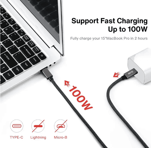
These connector type names tell you nothing about data speed, charging capability, or cable quality. A USB Type-C connector can house a cable built to USB 2.0 specifications with 28 AWG wire that barely delivers 500mA charging current1, or it can house a cable built to USB 3.2 specifications with 24 AWG wire and full shielding that delivers 100W power and 20Gbps data transfer. The connector shape is identical—the wire construction is completely different.

I see this confusion daily when customers request "USB-C cables" without specifying wire gauge, shielding requirements, or pin configuration. They match the device port shape and expect the cable to deliver whatever performance their device supports. The physical connector cannot deliver performance—only the wire specification inside can.
USB connector types separate into five main categories based on physical interface design:
| Connector Type | Physical Shape | Primary Application | Pin Count Range |
|---|---|---|---|
| Type-A | Rectangular, one-direction insertion | Host devices, computers, chargers | 4-9 pins |
| Type-B | Square, one-direction insertion | Peripheral devices, printers | 4-9 pins |
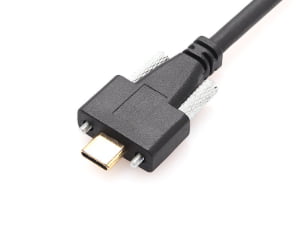
| Type-C | Oval, reversible insertion | Modern devices, universal connectivity | 24 pins |
| Micro USB | Small rectangular, one-direction insertion | Mobile devices, legacy equipment | 5 pins |
| Mini USB | Medium rectangular, one-direction insertion | Cameras, older mobile devices | 5 pins |
The pin count determines which signals the connector can physically carry, but it does not determine whether the cable wire construction actually delivers those signals properly. A 24-pin Type-C connector can connect all pins physically while only wiring 4 pins internally for basic USB 2.0 functionality. I confirm specifications for cables where customers paid for Type-C connectors expecting USB 3.1 performance but received Type-C shells with USB 2.0 wire construction inside.
Type-A connectors dominated as host-side interfaces for 20 years. The rectangular shape forces one-direction insertion and typically provides power output for downstream devices. Type-A appears on computer ports, wall chargers, and power banks. The 4-pin Type-A connector handles USB 2.0 signals. The 9-pin Type-A connector adds USB 3.0 capability with additional pins for SuperSpeed data lanes. These connectors look nearly identical externally—the internal pin configuration determines actual capability.
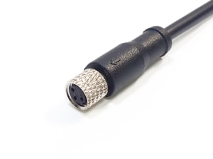
Type-B connectors serve peripheral devices like printers and external drives. The square shape prevents accidental connection to host ports. Standard Type-B handles full-size peripherals. Micro-B shrinks the interface for mobile devices. Mini-B served as the mobile standard before Micro-B replaced it. Each size variation exists in both USB 2.0 and USB 3.0 versions with different pin counts and internal wiring requirements.
Type-C emerged as the universal connector standard2 that handles both host and peripheral roles through reversible design. The 24-pin configuration supports USB 2.0, USB 3.1, USB 3.2, Thunderbolt 3, DisplayPort, and Power Delivery protocols3 depending on internal wire construction and device capability. This creates the biggest specification confusion I see—customers assume Type-C automatically means high performance when the connector type only defines the physical interface that could support high performance if the wire construction matches.
How do USB versions differ from USB connector types?
USB versions define protocol specifications that govern data transfer speed, power delivery capability, and signal requirements. USB 2.0 specifies 480 Mbps data transfer with 2.5W power delivery4. USB 3.0 specifies 5 Gbps data transfer with increased power capability5. USB 3.1 and 3.2 specify even higher speeds with different naming conventions6 that confuse even experienced buyers.
USB versions set the performance ceiling that requires specific wire construction to achieve. A cable can use any connector type with any USB version protocol, but it only delivers the promised performance when internal wire gauge, shielding, and pin configuration match the protocol requirements. Version number and connector type are independent specifications that must both align with your application needs.

I receive requests for "USB 3.0 Type-C cables" where customers assume the version number guarantees performance. USB 3.0 requires specific wire construction to deliver 5 Gbps transfer rates—this means 28 AWG or heavier gauge for data pairs, twisted pair configuration for differential signaling, aluminum foil shielding for each data pair, and proper impedance control throughout cable length. A Type-C connector can physically house wire that meets none of these requirements while still fitting the device port perfectly.
USB version specifications establish performance requirements:
| USB Version | Max Data Speed | Max Power Delivery | Key Wire Requirements |
|---|---|---|---|
| USB 2.0 | 480 Mbps | 2.5W (5V/500mA) | 28 AWG minimum, 4-wire configuration |
| USB 3.0 (3.1 Gen 1) | 5 Gbps | 4.5W (5V/900mA) | 28 AWG data pairs, individual shielding, 9-wire configuration |
| USB 3.1 (3.1 Gen 2) | 10 Gbps | 100W with PD | 26 AWG or heavier, full shielding, 24-wire for Type-C |
| USB 3.2 | 20 Gbps | 100W with PD | 24 AWG recommended, enhanced shielding, dual-lane configuration |
These wire requirements are not optional suggestions—they are minimum specifications to achieve the version's performance level. A cable built with 30 AWG wire and no shielding will physically connect through USB 3.1 connectors but cannot deliver 10 Gbps data transfer. The version number describes protocol capability that only manifests when wire construction supports it.
Wire gauge directly affects current carrying capacity and voltage drop over cable length. USB 2.0 charging cables typically use 24 AWG wire for power conductors to minimize voltage drop when delivering higher charging current than the 500mA protocol minimum. A cable built to USB 2.0 protocol specifications with 28 AWG data wires but 30 AWG power wires will charge slowly despite having correct connector type and correct USB version rating. I troubleshoot these failures regularly when customers report devices charging slowly or not charging despite using "correct" cables.
Shielding requirements increase with data transfer speed to prevent electromagnetic interference. USB 2.0 cables function without shielding in many applications. USB 3.0 requires individual foil shielding around each twisted data pair plus overall braid shielding7 to maintain signal integrity at 5 Gbps. USB 3.1 and 3.2 require enhanced shielding with both aluminum foil and copper braid layers. Cables built with correct connectors and correct wire gauge but inadequate shielding will show intermittent connection failures, slow data transfer, or complete protocol downgrade to USB 2.0 speeds.
Pin configuration must match the USB version protocol requirements. USB 2.0 uses 4 pins—power, ground, and two data signals. USB 3.0 adds 5 more pins for SuperSpeed data lanes and enhanced grounding. USB 3.1 Type-C uses all 24 pins for dual-lane SuperSpeed, Power Delivery negotiation, alternate modes, and enhanced power delivery. A cable can physically wire only the USB 2.0 pins inside a Type-C connector shell, creating a cable that fits Type-C ports but operates at USB 2.0 speeds only. This is the most common specification mismatch I see in customer complaints.
Why does wire gauge matter more than connector type for charging applications?
Wire gauge determines electrical resistance per unit length8, which directly controls voltage drop and current carrying capacity. Thicker wire gauge means lower gauge numbers and lower resistance. 24 AWG wire has lower resistance than 28 AWG wire9. Lower resistance means less voltage drop when current flows through the cable, which means more voltage reaches your device for charging.
Charging performance depends on delivering sufficient current at sufficient voltage to the device battery management system. A cable that drops voltage below the device's minimum threshold will charge slowly or not charge at all, regardless of connector type or USB version rating. Wire gauge is the primary specification that determines whether your device receives the power your charger provides.

I see this failure most frequently with long charging cables. A customer orders 2-meter USB-C cables expecting fast charging because their devices support USB Power Delivery. The cable uses Type-C connectors on both ends and claims USB 3.1 compatibility. The wire inside measures 28 AWG. At 2-meter length with 3A charging current, the voltage drop exceeds 0.8V on a 5V charging circuit—reducing delivered voltage to 4.2V or lower. Many devices stop charging below 4.5V10 even though the cable physically connects and the charger outputs correct voltage.
Wire gauge affects charging through these electrical relationships:
| Wire Gauge (AWG) | Resistance (Ω/m) | Voltage Drop at 2A over 1m | Voltage Drop at 3A over 2m | Safe Current Capacity |
|---|---|---|---|---|
| 24 AWG | 0.0842 | 0.168V | 0.505V | 3.5A continuous |
| 26 AWG | 0.1339 | 0.268V | 0.803V | 2.2A continuous |
| 28 AWG | 0.2127 | 0.425V | 1.276V | 1.4A continuous |
| 30 AWG | 0.3381 | 0.676V | 2.029V | 0.86A continuous |
These numbers show why a 2-meter cable built with 28 AWG wire cannot deliver 3A charging current without unacceptable voltage drop. The 1.276V drop on a 5V circuit means the device receives only 3.724V—below the threshold where most battery management systems switch to trickle charging or stop charging entirely. The connector type is irrelevant to this electrical limitation.
Cable length multiplies the wire gauge problem. A 1-meter cable with 28 AWG wire delivers acceptable performance for 2A charging with 0.425V drop. The same wire gauge at 2-meter length creates 0.850V drop at the same current—potentially dropping below device charging thresholds. Customers often request longer cables without understanding that wire gauge must increase as length increases to maintain the same charging performance.
I manufacture cables where customers specify "fast charging" capability without specifying wire gauge requirements. Fast charging means different things depending on device protocol—it might require 2A at 5V, 3A at 9V, or 5A at 20V for USB Power Delivery applications. Each current level requires different minimum wire gauge to avoid excessive voltage drop. A cable built with 28 AWG wire charges a 5W phone acceptably but fails to fast charge a 45W laptop through the same USB-C connector.
Wire gauge also determines heat generation during charging. Thinner gauge wire has higher resistance, which converts more electrical energy to heat when current flows11. A cable delivering 3A through 30 AWG wire generates significant heat that can damage cable insulation, reduce cable lifespan, or create safety hazards. This is why USB Implementers Forum specifications mandate minimum wire gauges for different current ratings—the physical limitation is not negotiable regardless of connector type used.
The relationship between wire gauge and charging performance creates specification requirements that buyers often miss:
- Any cable claiming 3A charging capability requires 24 AWG minimum for power conductors, regardless of connector type
- Any cable exceeding 1.5 meters length needs heavier gauge than 28 AWG to maintain voltage at 2A charging current
- Any cable supporting USB Power Delivery at 60W or 100W requires 22 AWG or 20 AWG power conductors12 even with correct Type-C connectors
These wire gauge requirements apply independently of connector type, USB version, or device compatibility. I confirm specifications where customers focused entirely on matching connector types and USB versions but never verified wire gauge, resulting in cables that physically connect but cannot deliver required charging performance.
What causes cables to fit physically but fail functionally?
Physical connector compatibility guarantees mechanical connection but reveals nothing about internal wire specification. A cable fits your device port when connector type matches port geometry. The cable functions properly only when internal wire gauge, shielding, pin configuration, and length all meet the electrical and signal requirements of your application.
The gap between physical fit and functional performance comes from treating cable selection as a connector matching problem instead of a wire specification problem. Most failures I troubleshoot involve cables where someone verified connector type compatibility without verifying wire construction requirements.

I see recurring failure patterns from this specification gap:
Customers buy "USB 3.0 cables" that use correct USB 3.0 Type-A and Type-B connectors but wire only the USB 2.0 pins internally. The cable physically connects and transfers data at 480 Mbps maximum instead of the 5 Gbps the customer expected. The connector type matched perfectly. The wire specification did not.
Customers buy "fast charging cables" that use correct USB-C connectors on both ends but use 28 AWG wire for power conductors. The cable physically connects and charges the device slowly because voltage drop reduces delivered power below fast charging thresholds. The connector type matched perfectly. The wire gauge did not.
Customers buy "USB-C to USB-C cables" expecting USB 3.1 performance but receive cables that wire only USB 2.0 signals through the Type-C connector shells. The cable physically connects and delivers 480 Mbps data transfer instead of 10 Gbps. Both connector types matched perfectly. The pin configuration did not.
Customers buy 3-meter charging cables that use correct connectors and correct wire gauge for 1-meter applications. The cable physically connects but voltage drop over 3-meter length prevents charging entirely. The connector type matched perfectly. The length-to-gauge ratio did not.
These failures all stem from the same root cause: assuming connector compatibility equals functional compatibility. The specification mismatch happens inside the cable where buyers cannot see it. I receive detailed device specifications, port photos, and connector type requirements from customers who never mention wire gauge, shielding type, or pin configuration because they do not realize these specifications determine whether the cable actually works.
Cable specification has multiple layers that must all align:
| Specification Layer | Visible Before Purchase | Determines Compatibility | Common Mismatch Pattern |
|---|---|---|---|
| Connector Type | Yes (physical shape) | Physical connection only | Correct connector, wrong wire specification |
| USB Version | Sometimes (on packaging) | Protocol capability ceiling | Correct version claim, inadequate wire construction |
| Wire Gauge | Rarely (buried in datasheet) | Current capacity, voltage drop | Correct connectors, insufficient wire gauge for current |
| Shielding Type | No (internal construction) | Signal integrity, EMI resistance | Correct gauge, inadequate shielding for data speed |
| Pin Configuration | No (internal wiring) | Which signals actually connect | All pins present, only subset wired internally |
The specifications buyers can easily verify are the specifications that matter least for functional performance. The specifications that determine actual performance are the specifications buyers rarely verify before purchase.
I handle specification confirmations where customers provide complete device port details, clear photos of connector types, and explicit USB version requirements. They do not provide wire gauge requirements, shielding specifications, or pin configuration details because they assume connector type and USB version together guarantee the cable will work. These assumptions create the "fits but fails" scenarios I troubleshoot repeatedly.
The solution requires treating cable selection as a wire specification problem first. Connector type selection comes after you determine required wire gauge for your current and length, required shielding for your data speed, and required
"USB-C - Wikipedia", https://en.wikipedia.org/wiki/USB-C. The USB Type-C specification allows for cables that implement only USB 2.0 functionality through the Type-C connector, wiring only the necessary pins for 480 Mbps data transfer and basic power delivery while leaving SuperSpeed pins unconnected. Evidence role: general_support; source type: institution. Supports: that USB Type-C connectors can physically house cables with only USB 2.0 signal wiring. Scope note: This describes what is technically permissible under the specification but does not quantify market prevalence ↩
"USB-C - Wikipedia", https://en.wikipedia.org/wiki/USB-C. The USB Type-C specification, released by the USB-IF in 2014, introduced a reversible 24-pin connector designed to serve as a universal interface for both host and peripheral devices across multiple protocols. Evidence role: definition; source type: institution. Supports: USB Type-C's design as a universal, reversible connector standard. ↩
"USB-C - Wikipedia", https://en.wikipedia.org/wiki/USB-C. The USB Type-C specification's 24-pin design enables support for multiple protocols including USB 2.0, USB 3.x data transfer, USB Power Delivery, and alternate modes such as DisplayPort and Thunderbolt 3/4, with specific protocols determined by device implementation and cable wiring. Evidence role: definition; source type: institution. Supports: the multiple protocols that USB Type-C connectors can support through their pin configuration. ↩
"USB hardware", https://en.wikipedia.org/wiki/USB_hardware. The USB 2.0 specification, maintained by the USB Implementers Forum, defines a maximum data transfer rate of 480 Mbps (High-Speed mode) and standard power delivery of 2.5W at 5V/500mA. Evidence role: definition; source type: institution. Supports: the official USB 2.0 specification for data transfer rate and power delivery. ↩
"USB 3.0 - Wikipedia", https://en.wikipedia.org/wiki/USB_3.0. USB 3.0 (also designated USB 3.1 Gen 1) specifies SuperSpeed data transfer at 5 Gbps and increases power delivery to 4.5W at 5V/900mA according to USB-IF standards. Evidence role: definition; source type: institution. Supports: the official USB 3.0 specification for data transfer rate and power delivery. ↩
"USB 3.0 - Wikipedia", https://en.wikipedia.org/wiki/USB_3.0. The USB-IF has revised USB naming conventions multiple times, with USB 3.1 Gen 2 specifying 10 Gbps and USB 3.2 reaching 20 Gbps, creating documented confusion in the industry regarding version nomenclature. Evidence role: general_support; source type: institution. Supports: the USB 3.1 and 3.2 speed specifications and naming convention changes. Scope note: This supports the existence of naming confusion but does not quantify how widespread the confusion is among buyers ↩
"USB 3.0 - Wikipedia", https://en.wikipedia.org/wiki/USB_3.0. USB 3.0 specifications require enhanced shielding to maintain signal integrity at 5 Gbps, including individual shielding for SuperSpeed differential pairs and overall cable shielding to minimize electromagnetic interference and crosstalk. Evidence role: mechanism; source type: institution. Supports: shielding requirements for USB 3.0 cables to maintain signal integrity at SuperSpeed data rates. Scope note: Specific shielding materials and construction methods may vary while meeting performance requirements ↩
"American wire gauge - Wikipedia", https://en.wikipedia.org/wiki/American_wire_gauge. According to electrical engineering standards, wire gauge (measured in AWG) has an inverse logarithmic relationship with cross-sectional area and therefore electrical resistance, with each decrease of three gauge numbers approximately doubling the wire diameter and halving the resistance. Evidence role: mechanism; source type: education. Supports: the inverse relationship between wire gauge (AWG) and electrical resistance. ↩
"American wire gauge", https://en.wikipedia.org/wiki/American_wire_gauge. Standard wire tables show that 24 AWG copper wire has approximately 0.0842 Ω/m resistance while 28 AWG has approximately 0.2127 Ω/m, making 24 AWG wire roughly 2.5 times lower in resistance. Evidence role: statistic; source type: education. Supports: the relative resistance difference between 24 AWG and 28 AWG wire. Scope note: These values are for copper wire at standard temperature and may vary with material composition and temperature ↩
"USB hardware - Wikipedia", https://en.wikipedia.org/wiki/USB_hardware. Battery management systems typically implement undervoltage protection that reduces or stops charging when input voltage drops below specified thresholds, commonly in the range of 4.5-4.75V for 5V USB charging circuits to ensure safe and efficient charging. Evidence role: general_support; source type: education. Supports: that devices have minimum voltage thresholds for charging operation. Scope note: Specific voltage thresholds vary by device manufacturer and battery chemistry; 4.5V is presented as a representative example rather than a universal standard ↩
"Joule heating - Wikipedia", https://en.wikipedia.org/wiki/Joule_heating. According to Joule's first law, electrical resistance in a conductor converts electrical energy to thermal energy at a rate proportional to I²R, where higher resistance in thinner gauge wire produces more heat for a given current flow. Evidence role: mechanism; source type: education. Supports: the physical mechanism by which electrical resistance in wire causes heat generation. ↩
"USB hardware - Wikipedia", https://en.wikipedia.org/wiki/USB_hardware. USB-IF cable specifications mandate minimum conductor sizes for Power Delivery applications, with cables supporting 3A (60W at 20V) requiring adequate gauge to limit voltage drop, and 5A (100W at 20V) cables requiring heavier conductors, typically 22 AWG or lower gauge numbers for power pins. Evidence role: definition; source type: institution. Supports: minimum wire gauge requirements for USB Power Delivery cables at high wattage levels. Scope note: Exact AWG requirements may vary based on cable length and acceptable voltage drop tolerances in the specification ↩