The Hidden Cost of Small Design Oversights in Wire Harness Projects
Most procurement managers and OEM engineers can point to obvious budget drivers like copper prices or connector shortages. But a quieter, more persistent form of cost leakage comes from choices made long before production starts. Wire harness design decisions that look harmless on a CAD screen—routing that appears neatly logical, wire lengths with a bit of extra buffer, connector families borrowed from a previous bill of materials—transform into real production headaches. A single overlooked bend radius tightness[1] in a harness branch can cascade into dozens of rework hours, elevated scrap rates, and delayed export shipments. These cost jumps rarely appear on the bill of materials as line items; instead they hide inside labor overruns, inspection failures, and emergency re-orders. Understanding where design intersects with manufacturing reality is the first step toward protecting margins on OEM wire harness programs.
Why Wire Harness DFM Review Matters Before the First Cut
Design for Manufacturability (DFM) is not a box to tick at the end of a project. When applied early and collaboratively, DFM bridges the gap between a 3D model’s ideal routing and the physical constraints of a production bench. Suppliers that coordinate drawing review before the first sample build can identify issues that engineers in a design office might never see: a crimping operator cannot meet a five‑millimeter bend radius on a shielded pair; a wire length specified without considering connector insertion depth forces the harness to twist; a label position chosen for visual appeal lands directly under a cable tie point, making it unreadable during final inspection.
Without this feedback loop, design iterations multiply. Each loop adds sample lead time, consumes material, and delays production ramp‑up. A production‑coordinated partner that performs DFM analysis—including connector mating verification, terminal cross‑section checks, and harness dress‑out simulation—can cut pre‑production rework by a measurable margin. Suppliers such as EDOM Electronics support OEM buyers with requirement review, connector matching, sample coordination, production follow‑up, inspection, and export‑ready packaging for custom cable assemblies and wire harnesses, turning initial drawings into production‑ready documents.
Connector Selection: Over‑Specification and Mating Confusion as Cost Drivers
Connector selection often becomes a default exercise: reuse the same series that appeared on the last project, or specify the most robust option available to stay “safe.” Both instincts can raise wire harness design cost without delivering additional value. An IP67‑rated sealed connector with gold‑plated contacts might add 30–40% to component cost[2] compared with a perfectly adequate IP54 alternative, while also extending procurement lead time when global stocks are thin. Uncommon footprint patterns force the assembly team to stock yet another housing, terminal, and seal kit, increasing inventory complexity and pick‑and‑place time.
Equally damaging is mating confusion. When a harness drawing mixes connector families without clear documentation—say, mixing Deutsch‑style circular connectors with M12 field‑attachables on adjacent branches—bench operators waste time cross‑referencing pinouts. Errors at the mating stage lead to reverse‑connected circuits discovered only during continuity testing, which then require re‑termination. A data‑driven comparison from mid‑volume production programs shows that consolidating onto a carefully chosen, standardized connector ecosystem[3] can reduce per‑assembly cost by 12–18%. That margin improvement comes not from material price negotiation but from fewer assembly errors, reduced inventory, and faster operator training.
Early connector review with a sourcing partner that understands both electrical performance and procurement reality helps reconcile these trade‑offs. For example, EDOM’s connector matching support during drawing review examines not just pin counts and current ratings but also availability, alternative sources, and mating consistency across the full harness. This approach keeps the bill of materials lean without sacrificing reliability.
Wire Length Tolerances: When ‘Just in Case’ Becomes Just More Waste
Wire length decisions often swing between two costly extremes. At one end, an engineer adds 10–15% extra length to every branch “just in case” the routing path changes, expecting that surplus can simply be bundled. At the other extreme, a sheet metal enclosure dictates exact center‑to‑center distances with no tolerance, leaving zero room for connector body depth, terminal insertion, or slight routing deviations. Both approaches inflate manufacturing cost.
Excess wire creates coil‑ups that must be tied, dressed, and visually inspected—adding minutes per harness. In tightly packed machinery, those coil‑ups also consume valuable space, forcing mechanical designers to enlarge enclosures or reroute other components. Conversely, wires cut too short cannot be stretched; a terminal that does not reach its housing land forces the production team to splice in additional wire or scrap the entire branch. Stranded conductors under tension also risk pull‑out during temperature cycling, a failure mode that surfaces only after the harness ships.
A practical guideline: specify wire lengths with a realistic ± tolerance that reflects the routing environment. For a simple linear route inside a straight conduit, ±3 mm may be sufficient[4]. For a branch that snakes through cable clamps, passes near rotating parts, and terminates at a bulkhead connector, ±10 mm may prevent production interruptions without creating unmanageable slack. The tolerance should be discussed with the harness manufacturer during the drawing review phase, not added as a last‑minute note.

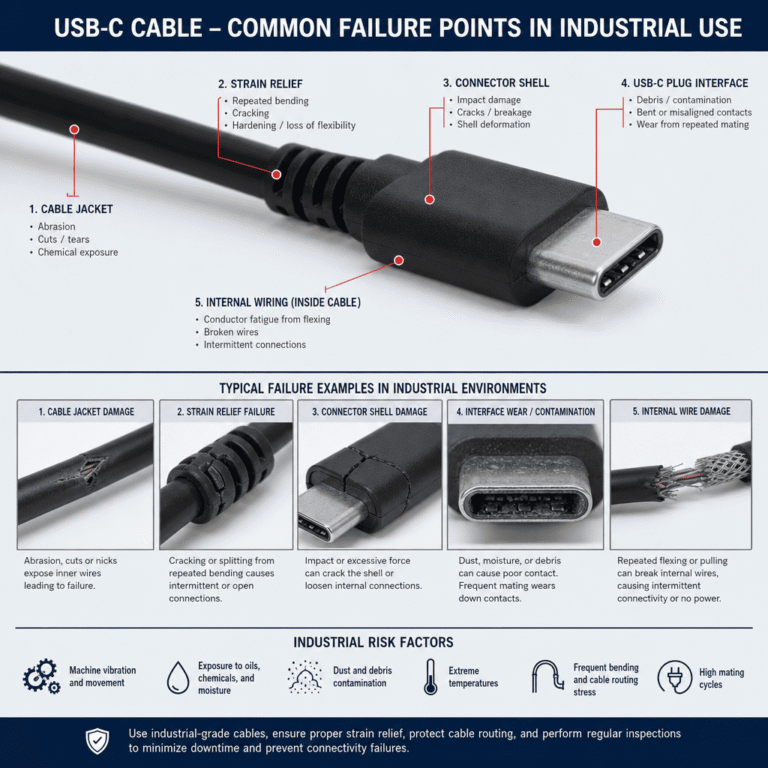
Bend Radius and Strain Relief: Mechanical Stress That Multiplies Rework
Every conductor has a minimum bend radius, yet harness drawings frequently show breakouts at right angles with no transition zone. Forcing a shielded multi‑conductor cable into a tight corner stresses the insulation, damages the shield, and can neck down individual conductors—creating hot spots that pass initial continuity but fail later under vibration. When such failures appear during final electrical test, the rework involves cutting back the harness branch, re‑terminating shields and conductors, and re‑inspecting, a chain of events that can add 20–30 minutes per harness[5] in a medium‑complexity assembly.
Strain relief designed as an afterthought compounds the problem. A harness that leaves the connector backshell with no grommet, boot, or clamp relies on the terminal crimp to absorb all mechanical load. Ad‑hoc fixes like hot glue or adhesive‑lined heat shrink[6] applied on the production bench may hold for a short time, but they degrade under thermal cycling and vibration. The result is an intermittent connection that triggers warranty claims—the most expensive form of rework an OEM can face.
Incorporating bend radius control and proper strain relief directly into the initial routing drawing is far cheaper than retrofitting a fix after pilot production. Designers should map out critical bending points, specifying bend radii at least three times the cable outer diameter[7] (or as recommended by the manufacturer), and document molded or clipped strain relief devices at every connector backshell and breakout junction. When a production‑coordinated supplier reviews these details before the first sample, the harness arrives ready to withstand both testing and field use.
Routing, Labeling, and Bundle Discipline: The Overlooked Assembly Time Multipliers
The way harness branches are drawn and documented can silently add minutes—sometimes hundreds of minutes across a production batch—to assembly labor. When branches cross each other without defined routing channels, operators spend extra time separating and aligning conductors, consuming more loom material to cover the tangle and lengthening visual inspection. Harness bundles that leave no space between conductors complicate continuity testing, as probes must be carefully inserted into dense connector faces one‑by‑one.
Label placement is equally critical yet frequently under‑specified. Labels positioned where they end up under a cable tie, or printed too small to read without magnification, force operators to pause and trace wires back to their origin. In high‑mix production environments—where multiple harness variants share the same bench—a single missing or misplaced label can trigger several minutes of identification work per harness. A comparative time study across similar harness designs showed that a well‑structured drawing with pre‑planned labeling points[8] and clear branch routing can reduce assembly time by up to 25%. That reduction flows directly to lower per‑unit labor cost and faster line throughput.
Drawing reviews that explicitly mark label positions, branch breakouts, and clearance zones give production teams a clear map. This practice, combined with sample reviews that place the harness in its intended application environment, catches assembly time traps before they become embedded in the production line.
Turning Design Review into a Cost‑Reduction Process: A Practical Workflow
All of the wire harness design mistakes described—over‑specified connectors, length extremes, ignored bend radii, absent strain relief, and chaotic routing—share a common root: they are fixed more cheaply on a drawing than on the production floor. Embedding a structured DFM review into the product development cycle converts the drawing from a static release document into an active cost‑containment tool.
- Joint drawing review. Before locking the bill of materials, the engineering team and the production‑coordinated supplier examine the harness drawing against real‑world manufacturing constraints. Connector families are verified for mating consistency and availability; terminal crimp specifications are matched to the exact wire gauge and insulation type; bend radius requirements are checked at every breakout.
- Sample build and test. The supplier produces a pilot harness using the intended production materials and processes. Continuity testing, insulation resistance checks, and visual inspection under assembly‑line lighting conditions reveal discrepancies between the CAD model and the physical bundle. Label readability, breakout orientation, and connector insertion are all evaluated.
- Process‑control feedback. Findings from the sample run feed back into the drawing and the manufacturing documentation. Routing channels are refined, length tolerances are adjusted, and strain relief devices are specified explicitly. The goal is not perfection on the first try but a rapid cycle of improvement that shrinks rework loops to a single round.
- Production launch with packaging validation. Once the harness design is stable, production quantities begin. The supplier performs ongoing continuity and appearance inspection, and validates export packaging to prevent transit damage—ensuring the cost savings achieved during DFM are not lost in shipment.
Collaborating with a partner that offers drawing review, connector matching, sample coordination, and production follow‑up eliminates the need for an OEM to maintain in‑house harness manufacturing expertise. For engineers and procurement managers looking to tighten designs and cut program cost, a manufacturability review that includes these steps provides a measurable return well before mass production begins.
For custom wire harness projects that require precise connector integration, OEM buyers can review real‑world examples such as the encoded servo serial port cable harness, which illustrates how detailed specification and production coordination come together in a single assembly.
Key Takeaways
- DFM is a cost lever, not a formality. Early supplier‑side design review catches tolerance, bending, and routing issues that multiply labor and scrap downstream.
- Connector over‑specification and poor mating documentation inflate BOM cost and rework. Standardizing on a consolidated connector ecosystem can reduce per‑assembly cost by 12–18% in typical medium‑volume programs.
- Wire length extremes—too long or too short—both hurt production. Realistic ± tolerances based on routing complexity eliminate coil‑up waste and splicing rework.
- Ignoring bend radius and strain relief drives field failures and warranty claims. Designing these mechanical protections into the initial drawing prevents expensive post‑test rework.
- Routing clarity and label placement directly affect assembly speed. Well‑structured drawings with pre‑planned labeling can reduce harness build time by up to 25%.