Quick Answer
Oil resistant cables in industrial manufacturing are validated through a sequence of standardized tests that measure dimensional stability, mechanical properties, and electrical integrity after exposure to specific oils at elevated temperatures. The most critical procedures include immersion testing for volume swell and mass change, tensile strength and elongation retention after oil aging, hardness change measurement, and dielectric strength verification. However, standard certification tests often apply single stressors in isolation, so experienced procurement teams now require evidence of combined-stress testing—such as simultaneous flexing and hot oil immersion—to predict real-world performance in hydraulic, gearbox, or cutting-fluid environments.
OEM Engineering Note: Need custom oil-resistant wire harnesses or continuous-flex drag chain cables certified to UL & IPC/WHMA-A-620? Explore Custom Cable Assemblies or Request a 24-Hour DFM Review & Quote.
The Hidden Risk in Oil Resistant Cable Specification
Many OEM engineers and procurement managers trust a cable’s oil resistance rating as a guarantee of field reliability. The datasheet may list compliance with UL oil resistance requirements, and the supplier includes a pass/fail test report. That confidence is often misplaced. A cable that survives 7 days of static immersion in IRM 902 oil at 60°C can still fail within a few months when flexed inside a machine tool cable carrier while simultaneously exposed to the same fluid at 75°C. The hidden risk is that standard test protocols rarely replicate the combined chemical, thermal, and mechanical stress cycling found in actual equipment.
Field failures typically appear as jacket swelling, embrittlement, cracking, or delamination that exposes conductors. In hydraulic power units, oil wicks along cable cores, degrading insulation resistance. In gearboxes and machining centers, cutting fluids with aggressive additives attack jacket compounds that were only validated against pure mineral oil. The disconnect between datasheet values and real operating environments costs production uptime and forces reactive maintenance. Understanding how oil resistant cables are actually tested—and the limitations of those tests—is essential for making informed sourcing decisions.
Standards and Certifications for Oil Resistant Cables
Procurement teams evaluating supplier test reports must first understand the standards that frame oil resistance claims. In North America, UL 62[1] and UL 758 are the foundational documents for flexible cord and appliance wiring material, respectively. These standards define the raw material aging requirements, establishing tensile strength and elongation retention benchmarks after specified oil exposure. Crucially, the foundational physical testing methodologies for these evaluations—such as volume swell, mass change, and mechanical properties—are governed by UL 2556 (Standard for Wire and Cable Test Methods).
Beyond the raw cable materials, finished assemblies are evaluated under IPC/WHMA-A-620. It is important to note a key distinction: while UL standards certify the compound’s chemical resistance, IPC/WHMA-A-620 serves as the workmanship acceptance criteria, verifying that connector backshells, sealing boots, potting, and strain reliefs retain their physical integrity and prevent fluid ingress after exposure to process fluids. Furthermore, IPC J-STD-001 adds soldering and termination quality requirements that become critical when oil ingress threatens joint reliability. Procurement specifications should also verify that oil-resistant jacket and insulation materials meet global environmental regulations. Full compliance declarations under RoHS and REACH must cover all compounds in the cable construction, not just the base polymer, because some flame retardants and plasticizers used to enhance oil resistance may contain restricted substances.
FAQ: How Specific Cable Properties Are Tested for Oil Resistance
Below are the primary test methods that form the backbone of oil resistance verification. Each is described with its purpose, procedure, and typical pass/fail thresholds drawn from industry norms such as UL and IEC test standards.
Immersion Testing for Volume Swell and Mass Change
Purpose: To determine the dimensional stability of the cable jacket and insulation after prolonged contact with oil. Swelling can compromise mechanical fit in connectors and cable glands, while mass loss signals plasticizer extraction that leads to embrittlement.
Procedure: A specimen is fully immersed in a specified oil type (often IRM 902 or IRM 903 per ASTM or UL methods) at a defined temperature—commonly 60°C, 75°C, or 100°C—for a set duration, typically 7 days. After removal, the specimen is wiped clean and immediately measured for mass and cross-sectional dimensions.
Pass/fail indicators: Many cable specifications permit a maximum volume swell of 25% to 30% and mass change within ±10%. Values beyond these thresholds suggest the compound is too reactive with the test oil for long-term service.
Tensile Strength and Elongation at Break After Aging
Purpose: To evaluate the degradation of mechanical integrity after oil immersion. Even if a jacket shows minimal swelling, chemical attack can reduce its ability to withstand bending, abrasion, and clamp pressure.
Procedure: Dumbbell-shaped specimens are cut from the jacket or insulation, then aged in oil under the same conditions as the immersion test. After aging, specimens are pulled in a tensile testing machine to measure the force at break and elongation. Results are compared to unaged controls.
Pass/fail indicators: UL 62 and similar standards generally require retention of at least 50% of the original tensile strength and 50% of the original elongation. A cable that retains 70% of tensile strength but only 30% elongation may still fail in dynamic applications due to embrittlement.
Hardness Change Measurement (Durometer): How to Identify High-Quality Oil Resistant Wire
Surface softening or embrittlement after oil exposure can be detected quickly with a durometer. Shore A hardness changes provide an early warning of seal integrity loss in connector backshells and cable glands, as well as reduced abrasion resistance. For design engineers and procurement teams, mastering this metric is essential for how to identify high-quality oil resistant wire during incoming material inspection.
The testing procedure measures hardness on both unaged and oil-aged jacket samples using a Shore A (or occasionally Shore D) durometer per ASTM D2240, executed under the framework of UL 2556 physical property evaluations. Under high-reliability industry specifications and Class 3 industrial standards, the pass/fail threshold is tightly controlled as follows:
- Acceptable Hardness Shift: Tightly limited within ±5 to ±8 points Shore A after the designated oil immersion period. A wider variance typically indicates severe plasticizer extraction/migration (which increases hardness and causes brittleness) or polymer matrix dissolution (which softens the jacket), rather than chemical cross-linking degradation since most PVC and PUR compounds used are thermoplastics. For standard compliance, this hardness and tensile retention evaluation determines whether a cable can be officially printed with UL OIL RES I (60°C rating) or the more stringent UL OIL RES II (75°C rating) markings.
- Risk of Large Increase: Signals severe material embrittlement, leading to jacket cracking during dynamic flexing.
- Risk of Large Decrease: Signals excessive plasticization or chemical dissolution, causing the jacket to lose its mechanical defense and tear easily.
Jacket Material Selection Framework: Quantitative Comparison
To assist design engineers in mapping laboratory test compliance to real-world environments, the following data outlines how the three most common outer jacket materials perform across standardized oil immersion and stress metrics:
| Jacket Material | Mineral Oil Resistance (IRM 902) | Synthetic Fluid Resistance (Ester/Glycol) | Typical Vol. Swell (7 Days @ 75°C) | Shore A Hardness Shift | Dynamic Flexing Compatibility |
|---|---|---|---|---|---|
| Specialty PVC (Oil Res I/II) | Good | Poor (Plasticizer Leaches) | +15% to +25% | -10 to -12 points | Moderate (Static/Occasional Flex) |
| TPU / PUR (Polyurethane) | Excellent | Excellent. Note: Polyether-based PUR must be specified over Polyester-based PUR in CNC machine environments to prevent hydrolytic degradation (hydrolysis) caused by water-soluble cutting fluids/emulsions. | < 5% | ±3 to ±5 points | Excellent (Continuous Drag Chain) |
| TPE (Thermoplastic Elastomer) | Excellent | Moderate | +5% to +12% | ±5 to ±7 points | High (Torsion & Torsional Flexing) |
Electrical Integrity Post-Exposure: Dielectric Strength and Insulation Resistance
Purpose: Chemical attack must not compromise the cable’s ability to withstand operating voltage or maintain high insulation resistance. These tests ensure functional safety after oil exposure.
Procedure: Following oil immersion and a recovery period, the cable assembly is subjected to a high-potential (hipot) test to verify dielectric strength, often at 1.5 to 2 times rated voltage plus 1000 volts, per IEC or UL procedures. Insulation resistance is measured with a megohmmeter, typically expecting values in the megaohm or gigaohm range.If you are unfamiliar with how these specific instruments fit into a broader incoming inspection workflow, read our guide on What Is a Cable Tester.
Pass/fail indicators: No breakdown or flashover during hipot, and insulation resistance above a minimum threshold (e.g., 100 MΩ) is a common acceptance criterion. In wet or oily environments, many engineers specify a higher minimum to account for surface leakage.
Performance of Oil Resistant Wire Under Stress: Why Single-Stress Data Misleads
Standard oil resistance evaluations apply a single stressor: oil immersion without simultaneous mechanical or electrical load. In contrast, real-world cable assemblies inside machine tools, robots, and hydraulic systems experience flexing, vibration, and temperature cycling while immersed in or splashed with oil. When these stressors overlap, degradation accelerates through mechanisms that standard tests do not capture.
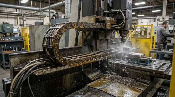
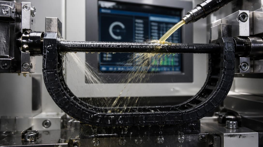
Consider a cable in a continuously flexing cable carrier on a CNC machining center. Hot cutting oil penetrates micro-cracks in the jacket, which then propagate under cyclic bending. The real-world performance of oil resistant wire under stress—where mechanical flex stress overlaps with chemical oil attack—is vastly different from static laboratory sheets. A jacket that passes 7-day static immersion at 60°C may develop deep cracks within 200,000 flex cycles when the same oil is present at 75°C during bending. Manufacturers performing combined-cycle protocols—oil immersion at rated temperature with simultaneous cyclic flexing—often find that cable life is reduced significantly compared to sequential testing, where the sample is aged first and flexed later. Experienced application engineers observe failure modes such as jacket fatigue cracking, conductor stranding breakage due to oil wicking, and connector seal blowout that never appear in single-stress test reports.
In hydraulic and gearbox environments, pressurized oil can infiltrate through connector interfaces. Once inside, it migrates along stranded conductors and degrades insulation resistance over time. A cable that passes a hipot test after simple immersion may fail within weeks in a pressurized system. These multi-stress failure patterns demonstrate why procurement teams must go beyond pass/fail stamps.
⚙️ Designing Heavy-Duty Equipment? Don’t Risk Cable Failure.
Standard datasheets don’t tell the whole story. At EDOM Electronics, we offer customized wire harnesses and cable assemblies proven to maintain their mechanical and electrical integrity under extreme environmental stresses.
- Strict adherence to UL 62, UL 758 & IPC/WHMA-A-620 Class 3 standards.
- 100% full material compliance declarations (RoHS & REACH).
- Coordinated engineering from custom connector matching to batch-level testing.
What Procurement Managers Should Require from Cable Suppliers
Translating technical test knowledge into supplier qualification requirements protects product reliability. When sourcing oil resistant cable assemblies, procurement managers can take the following actions:
- Specify test parameters, not just standards. Request test reports that clearly list the oil type (e.g., IRM 902), temperature, duration, and any mechanical load conditions applied during the test. A report that states “UL 62 compliant” without these details is insufficient.
- Ask about combined stress testing. Inquire whether the supplier or its cable manufacturer has evaluated the assembly under flexing, torsion, or temperature cycling during oil exposure. Even limited combined testing data can expose weaknesses that single-stress tests hide.
- Include IPC/WHMA-A-620 class criteria. For finished cable assemblies, specify acceptance requirements based on the appropriate class—Class 2 for industrial equipment or Class 3 for high-performance applications. This ensures that crimp quality, connector fit, and insulation integrity are judged against standard workmanship expectations after oil exposure, not just during initial build. For custom cable assembly programs, referencing these criteria in the quality plan aligns manufacturing output with end-use demands.
- Verify environmental declarations thoroughly. Confirm that RoHS and REACH declarations explicitly cover all jacket, insulation, and filler compounds. Some oil-resistant formulations rely on plasticizers that face regulatory scrutiny, and compliance gaps can block market access in Europe or other regulated regions.
- Insist on batch-level process control evidence. A one-time type-test certificate from years ago does not guarantee consistent oil resistance across production lots. Ask for periodic conformance testing data and evidence of in-process inspections.
Suppliers that coordinate production from multiple facilities—including harness assembly, connector matching, and testing—must demonstrate how oil resistance verification flows through the entire process. For example, a coordinated wire harness manufacturing supply chain should maintain traceability from compound batch to finished assembly, with oil resistance checks at incoming material inspection and final product audit.
Integrating Oil Resistance Data into Your Quality Assurance Process
Once reliable test data is collected, OEM engineering and quality teams can build a practical verification plan. Design engineers should map each cable in the bill of materials to its expected service conditions, creating a chemical-hardiness profile that lists the oil types, temperatures, and mechanical stresses the assembly must withstand. This profile then guides incoming inspection, process control, and final verification.
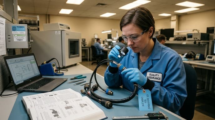
Incoming inspection can include durometer checks on jacket samples from each reel lot, compared to the unaged baseline provided by the cable manufacturer. Process control during assembly and routing should follow IPC J-STD-001 soldering and termination criteria, with attention to strain relief and connector sealing that prevents oil ingress. Final verification under IPC/WHMA-A-620 can add a sample-based oil immersion test on completed assemblies, particularly for Class 3 programs where field failure risk is intolerable.
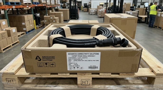
For multi-source cable assembly programs, this approach avoids overloading receiving inspection. By working with a supplier that manages requirement review, drawing assessment, connector matching, sample coordination, and final inspection under one quality umbrella, procurement teams can centralize oil resistance verification without managing a patchwork of subcontractors. Suppliers such as EDOM Electronics support OEM buyers with this integrated approach—confirming specifications against environmental conditions, coordinating sample builds with pre-agreed oil resistance criteria, and delivering export-ready assemblies after continuity checks, appearance inspection, and packaging designed to prevent transit damage. This kind of coordinated workflow turns test data into a managed process rather than a paperwork exercise.
Beyond the Spec Sheet: The Future of Oil Resistance Verification
Industry trends point toward application-specific, combined-stress testing as the new baseline for high-reliability equipment. Instead of generic oil resistance claims, cable suppliers are beginning to offer test programs tailored to a customer’s actual fluid environment—transmission oil, ester-based hydraulic fluids, or water-glycol coolants—at the temperatures and flexing cycles expected in service. Digital twin models and accelerated lifetime test protocols now allow engineers to simulate years of combined stress in a laboratory and predict failure patterns, enabling earlier design intervention.
Partnerships between OEM engineering teams and manufacturing coordinators are becoming the key to preventing premature field failures. When cable and harness suppliers participate early in the design phase, they can recommend jacket compounds, connector sealing methods, and routing strategies that mitigate oil-related degradation. This collaboration shifts the focus from after-the-fact test validation to proactive design for chemical ruggedness, reducing warranty costs and improving equipment uptime.
Frequently Asked Questions
How long does a typical oil resistance test take?
Standard immersion tests for mass change and tensile retention run for 7 days at constant temperature. Combined-stress test cycles with flexing can extend from several hundred thousand cycles to several weeks of continuous testing, depending on the flex rate. Rush programs can sometimes obtain preliminary data from accelerated protocols, but full validation requires the full duration.
Can one cable be suitable for both mineral and synthetic oils?
Not always. A jacket compound that resists mineral oil well may swell excessively in a synthetic ester fluid. Procurement teams should specify the exact oil type(s) the cable will encounter and request test data for each. Some suppliers maintain compatibility databases but each application should be individually verified.
Does RoHS compliance affect oil resistance performance?
Certain flame retardants and plasticizers that previously enhanced oil resistance are now restricted under RoHS. Cable manufacturers have reformulated compounds to meet both oil resistance and environmental requirements. It is essential to request full material declarations that confirm the specific jacket compound meets both performance and regulatory needs.
How do I know if my cable assembly supplier follows IPC/WHMA-A-620?
Ask for documentation of operator training and process certifications. Many reputable assembly houses have technicians trained and certified to IPC/WHMA-A-620, and they can provide certificates or audit reports. During initial qualification, request a sample build and inspect it to the desired class criteria, paying particular attention to crimp heights, insulation clearance, and strain relief—areas that directly influence oil ingress resistance.
Is oil resistance testing required for all industrial cable assemblies?
Not for all equipment, but any cable assembly that will be exposed to lubricants, coolants, hydraulic fluids, or cleaning chemicals during normal operation should be validated. Even incidental splashing can degrade non-resistant materials over time, causing insulation failure or connector corrosion. A risk assessment early in design clarifies which cables require oil resistance verification.
Key Takeaways
- Oil resistant cable ratings derived from static immersion tests may not predict performance under combined mechanical, thermal, and chemical stress.
- Critical test methods include immersion for swelling, tensile and elongation retention, hardness change, and post-exposure electrical integrity.
- Standards such as UL 62, IPC/WHMA-A-620, and IPC J-STD-001 provide acceptance criteria, but buyers should require detailed test parameters, not just compliance statements.
- Combined-stress testing—flexing during hot oil immersion—reveals failure mechanisms that single-stressor tests miss and should be part of supplier qualification for demanding applications.
- Integrating oil resistance data into a coordinated quality assurance process, from material incoming inspection to final assembly verification, ensures consistent reliability across production batches.
For deeper guidance on inspection, end-of-line testing, and export packaging tailored to international OEM programs,
learn more about our wire harness OEM services.