
Quick Answer
A wiring harness is an organized assembly of wires, terminals, connectors, and protective sleeving that distributes electrical power and signals along a predefined routing path. It integrates multiple circuits with branch breakouts, reducing installation time, preventing mis-wiring, and protecting conductors from vibration, heat, and environmental stress. Unlike a simple wire bundle, a full harness includes strain relief, conduit, and locking connectors to maintain reliability in demanding OEM applications.
Beyond Simple Bundles: Understanding the True Definition of a Wiring Harness
Too often, procurement teams and even some design engineers treat a handful of wires zip-tied together as if it were a production‑ready harness. The two serve fundamentally different purposes. A loose wire bundle offers no organized routing, no standardized termination, and no defense against the mechanical and thermal stresses present in real‑world equipment. A wiring harness, by contrast, is a purpose‑engineered sub‑assembly that transforms individual conductors into a protected, routed, and connectorized distribution network.
The core definition: a wiring harness is a collection of single‑core wires or multi‑conductor cables, each cut to length, terminated with compatible contacts or connectors, and then bound together with a combination of sheathing, loom, and mounting hardware. The harness follows a mechanical routing diagram that governs branch lengths, breakout positions, and strain‑relief points. This structured design slashes installation errors on the OEM floor, cuts assembly time, and dramatically improves long‑term reliability compared to hand‑routed individual wires (see our detailed guide on what a wire harness does in OEM equipment assemblies to understand component interaction and RFQ drawing requirements).
When a buyer mistakes a simple wire bundle for a harness, they usually overlook critical protective elements, such as split conduit, braided sleeving, grommets, and locking connector housings. These components are what separate a wiring harness that survives years of vibration and temperature cycling from one that will chafe, short, or fatigue within months. The following sections unpack exactly those components and the engineering decisions behind them.
Core Components of a Wiring Harness
A wiring harness is more than the sum of its wires. Each element in the assembly must be selected to match the electrical load, environmental exposure, and mechanical fixation requirements of the final installation. The four cornerstone component categories are the conductors themselves, the connector system, the protective sheathing, and the routing and strain‑relief hardware.
Conductors and insulation. Wire selection starts with the American Wire Gauge (AWG) and stranding configuration. Finer stranding, such as 19‑ or 26‑strand construction, provides flexibility needed for harnesses that must bend around tight chassis corners, while thicker single‑strand conductors serve static, high‑current paths. However, finer multi-strand conductors require tighter strip-length tolerances and tooling maintenance to prevent bird caging and wire strand fraying during stripping and termination. The base metal is almost always copper or tinned copper; tinning helps suppress oxidation in humid or corrosive environments without the cost of full silver or nickel plating. However, unauthorized material substitution remains a major quality risk in sub-tier supply chains—learn how to detect copper-clad aluminum wire before nonconforming reels reach production. The insulation jacket—PVC, cross‑linked polyethylene (XLPE), silicone, or fluoropolymers—determines the temperature envelope and resistance to oil, fuel, and UV.
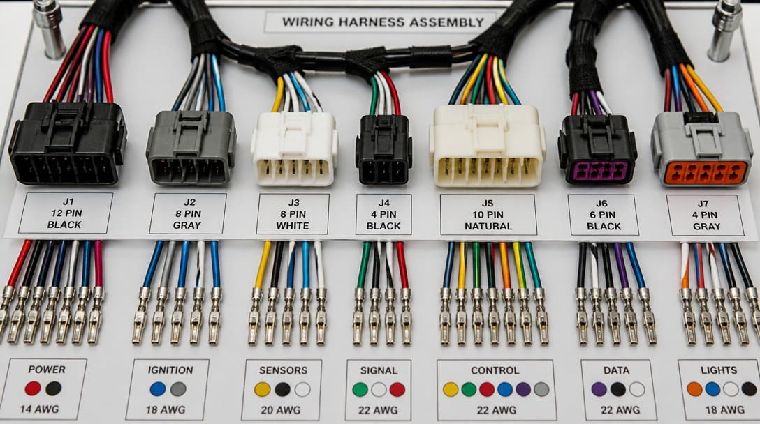
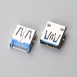
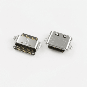
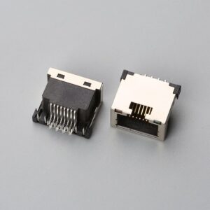
Connector and terminal system. Each harness breakout ends in a connector or terminal that mates with the equipment interface. The connector housing, pin‑and‑socket contacts, wire seals, and secondary locking mechanisms must all be compatible. Correct terminal crimp height and pull-force values are critical control points throughout the wiring harness manufacturing process; a poorly crimped terminal can overheat or disengage under vibration. Mating pairs are often keyed and color‑coded to prevent assembly mistakes, a feature that saves significant downtime on production lines.
Protective sleeving. The outermost layer of a harness is typically some form of conduit or wrap. Split convoluted tubing offers high impact protection and easy installation over already‑terminated wires. Braided expandable sleeving provides a tight, flexible skin that resists abrasion and allows heat dissipation. Spiral wrap is used where frequent breakouts need to be accessed, while heat‑shrink tubing seals transitions against moisture. The choice of sleeving directly influences how well the harness handles chafing at panel edges and exposure to hydraulic fluids or cleaning chemicals.
Strain relief and routing hardware. Harnesses are rarely allowed to float freely inside a machine. Mounting clips, fir‑tree ties, P‑clips, and grommets fix the bundle along a defined path and absorb pulling forces before they reach the connector contacts. A well‑placed custom cable assembly design approach often includes molded strain‑relief boots or cable glands at entry points, preventing wire breakage exactly where failures are most likely to start.
Materials and Insulation: Balancing Performance and Durability
The service life of a wiring harness is dictated largely by the insulation system. Engineers specify materials based on the equilibrium between thermal endurance, chemical resistance, flexibility, and cost.
Polyvinyl chloride (PVC) remains the workhorse for general‑purpose industrial and low‑voltage automotive interiors, offering moderate temperature resistance up to about 105 °C and decent oil resistance, but it can stiffen at cold extremes. Cross‑linked polyethylene (XLPE) raises the temperature ceiling to 125 °C or higher while delivering superior cut‑through and chemical resistance, making it a go‑to choice for engine bay and heavy machinery harnesses. Silicone rubber insulations excel in high‑temperature, high‑flexibility applications like medical devices and hot‑end industrial sensors, though they require careful handling against tearing. Fluorinated ethylene propylene (FEP) and other fluoropolymers provide outstanding chemical inertness and a very wide temperature window, but at a premium cost.
Conductor plating adds another layer of protection. Tinned copper offers a strong cost‑performance balance for most moist environments; silver plating reduces high‑frequency signal loss and withstands elevated temperatures up to 200 °C; nickel plating delivers extreme oxidation resistance for aero‑engine and high‑heat sensor applications. The choice of plating must be mated intelligently with the terminal contact material to avoid galvanic corrosion at the crimp interface.
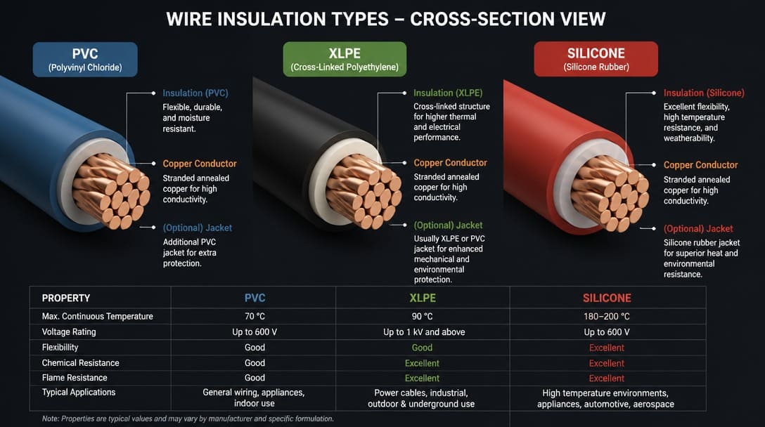
Insulation selection directly feeds into certification requirements. Many global OEMs ask for UL‑recognized wire types carrying UL style numbers such as UL 1015[1] or UL 3302. These style numbers confirm that the wire has passed specified flame, voltage, and temperature tests. Meanwhile, RoHS compliance—Restriction of Hazardous Substances—is a baseline requirement for selling into the European Union and many other regulated markets, covering lead‑free solders, PVC stabilizers, and brominated flame retardants. A harness bill of materials that lists UL file numbers and RoHS‑compliant material grades provides instant confidence during supplier evaluation.
Protective Elements: Conduit, Loom, and Strain Relief for Harsh Environments
The difference between a wire bundle that survives a five‑year field deployment and one that fails in months often lies in the protective accessories that are invisible in a cost‑only comparison. These elements deserve explicit attention in any procurement specification.
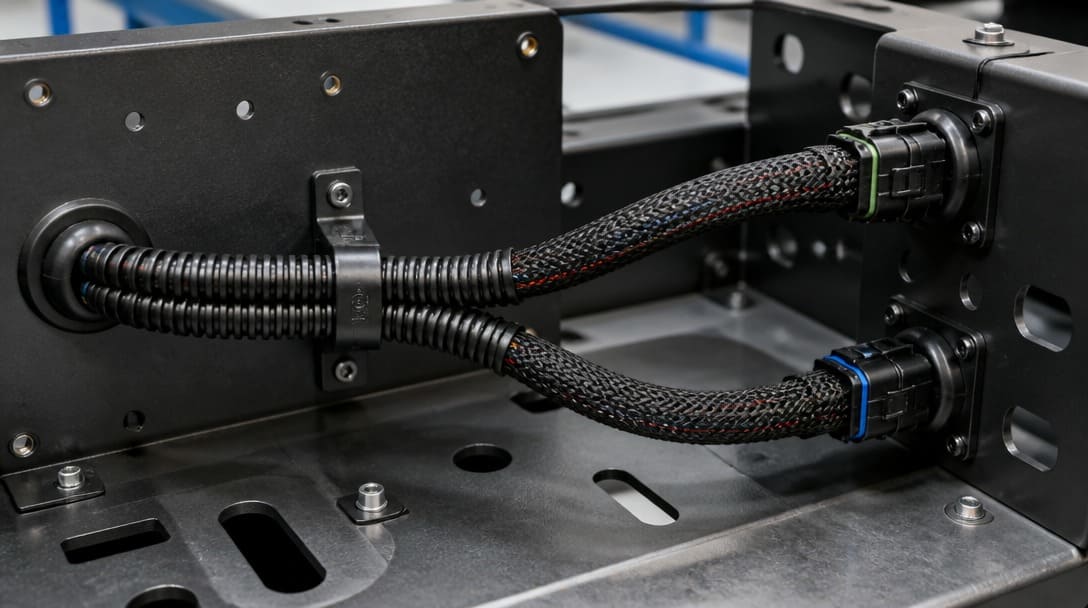
Mechanical protective layers start with the external conduit. Split convoluted conduit, typically made from polyamide (PA) or polypropylene (PP), absorbs impact and resists crushing in heavy machinery. Self‑wrapping braided sleeving, often polyester or Nomex, provides a lightweight, flexible shield that does not trap moisture. For high‑temperature zones near exhaust manifolds or turbine casings, rigid fiberglass or silicone‑coated loom tubes keep conductors safe while maintaining a minimum bend radius.
Strain relief becomes non‑negotiable wherever a connector exits a chassis wall or a cable enters an equipment gland. Molded backshells, threaded cable glands with integrated sealing rings, and properly sized grommets prevent wire flexure from concentrating at the point of termination. A harness that omits these details may pass a bench continuity test but will accumulate broken strands after the first hundred thermal cycles.
Moisture management also falls under protection. Drain holes in low‑point conduits, sealed splices using dual‑wall adhesive‑lined heat shrink, and connector interfaces rated to IP67 or IP69K stop water wicking up the wire strands. When procurement teams focus only on wire gauge and connector part numbers, these protective design choices are frequently overlooked—repeating the common mistake of assuming a wire bundle is functionally equivalent to a properly engineered harness.
Wire Harness vs. Cable Assembly: Key Differences and When to Choose Each
B2B buyers frequently confuse wiring harnesses with cable assemblies, sometimes using the terms interchangeably on requests for quotation. The distinction is important because the two products follow different design rules, manufacturing processes, and testing standards.
A cable assembly is a single multi‑conductor cable, usually with an overall ruggedized jacket, terminated with connectors on both ends. It provides a point‑to‑point external link between two pieces of equipment, operating much like a heavy‑duty extension cord for signal or power. The cable’s outer jacket offers environmental protection, so individual conductors inside do not require additional looming.
A wiring harness, by contrast, is a routed network of individual wires or cables that branch out to multiple connection points inside a vehicle, control cabinet, or machine frame. Each wire may have its own insulation and may be routed to a different connector. The harness depends on its protective sleeving, routing clips, and strain relief to handle abrasion, vibration, and heat inside the enclosure. Think of the harness as the electrical skeleton of a product, while the cable assembly is a single robust tendon linking two modules.
The following table summarizes the primary contrasts:
| Parameter | Wiring Harness | Cable Assembly |
|---|---|---|
| Structure | Multiple branches with single wires or sub‑cables, often protected by multiple sleeve types | Single multi‑conductor cable with an overall jacket, point‑to‑point |
| Typical use | Internal power/signal distribution inside a chassis, vehicle, or panel | External connections between separate enclosures or moving modules |
| Environmental protection | Provided by conduit, loom, grommets, and heat shrink along the route | Provided primarily by the cable’s integral jacket and connector sealing |
| Complexity | High: multiple lengths, breakouts, and connector types per assembly | Lower: two connectors on a single cable, though overmold options increase complexity |
| Testing | Point‑to‑point continuity per net, plus harness‑level crimp and workmanship inspection | Continuity and, when required, high‑pot or signal integrity testing end‑to‑end |
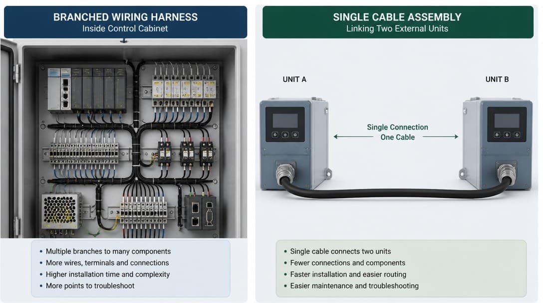
For an OEM equipment manufacturer, the rule of thumb is straightforward. When the electrical distribution runs inside a machine and needs to feed power or signals to multiple separated components, specify a wiring harness. When connecting that machine to an external sensor, motor, or another control box through a bulkhead, choose a cable assembly. Approaching a supplier with this clarity ensures the right manufacturing approach, from wiring schematics versus point‑to‑point drawings to the appropriate protective layer selections. Working with an experienced partner can streamline the custom cable assembly and harness specification stage, reducing the back‑and‑forth that delays first‑article builds.
Industry Standards and Quality Benchmarks: IPC/WHMA‑A‑620, SAE J1128, and Beyond
Specifying a wiring harness without citing acceptance standards leaves quality open to interpretation. Three key references should be on every procurement professional’s checklist.
IPC/WHMA‑A‑620 is the globally recognized standard for acceptance of cable and wire harness assemblies. It defines three classes of workmanship—Class 1 for general electronic products, Class 2 for dedicated‑service equipment, and Class 3 for high‑reliability applications—each with escalating requirements for crimp quality, solder joint inspection, and documentation. A harness built to IPC/WHMA‑A‑620 Class 2 or 3 comes with measurable criteria for insulation crimp support, bellmouth dimensions, and pull‑force minimums, eliminating subjective “looks good” judgments. Buyers sourcing from international manufacturing partners should request that first‑article inspection reports explicitly reference the applicable IPC/WHMA‑A‑620 class.
SAE J1128 covers low‑tension primary cable used in automotive electrical systems, specifying conductor sizes, insulation wall thickness, voltage ratings, and temperature classes ranging from 80 °C to 125 °C. When a harness is destined for a vehicle platform, referencing SAE J1128 for the base wire ensures that the raw material meets the thermal and mechanical demands of under‑hood or chassis routing. This standard also interfaces with other SAE documents governing connector performance and environmental durability.
For North American and many global markets, UL certification further validates wire insulation integrity. UL recognition or listing, displayed through UL file numbers, confirms independent testing to standards such as UL 758 for appliance wiring material or UL 62 for flexible cords. Together, adherence to IPC/WHMA‑A‑620, SAE J1128 where applicable, and UL component recognition creates a defensible quality framework that protects the buyer from field failures and warranty claims.
Typical Applications Across Industries
The foundational principles of harness engineering apply consistently, but the emphasis shifts dramatically depending on the end‑use environment.
- Automotive and off‑highway vehicles. Engine harnesses withstand continuous vibration, oil spray, and under‑hood temperatures exceeding 125 °C. Transmission and chassis harnesses must resist stone impact and salt spray. Infotainment and ADAS sensor harnesses require precise impedance control and data integrity, often integrating coaxial or differential‑pair wiring within the same breakout as power circuits.
- Industrial machinery and robotics. Control‑panel harnesses manage hundreds of I/O points while fitting within tight wireways. Robotic‑arm harnesses must survive millions of flex cycles, demanding high‑flex stranded conductors and torsion‑resistant sleeving. Oil‑resistant XLPE or polyurethane jackets are standard to protect against cutting fluids and hydraulic oil.
- Medical devices. Diagnostic equipment harnesses prioritize cleanliness, chemical sterilization resistance, and absolute reliability. Silicone‑jacketed wires and sealed connector interfaces prevent fluid ingress. Workmanship standards are typically at the IPC/WHMA‑A‑620 Class 3 level, with strict traceability requirements.
- Aerospace and defense. Weight is critical, leading to the use of lightweight composite conduit and carefully optimized conductor sizing. Fire‑resistance requirements such as FAR 25.853 and low‑smoke, low‑toxicity insulation materials drive material selection. Cryogenic and high‑altitude resilience add additional qualification burdens.
- Renewable energy. Solar‑tracker harnesses face decades of UV exposure, wide daily temperature swings, and rodent damage risk. Wind‑turbine pitch‑control harnesses flex with blade rotation and must operate in nacelle temperatures that can drop below ‑40 °C.
Each of these applications reinforces why treating a harness as a mere wire bundle is a risky shortcut. The protective and material choices discussed earlier are not optional extras; they are what make the harness fit for purpose.
Actionable Guidance for Specifying or Sourcing Wiring Harnesses
Procurement managers and design engineers can reduce project risk significantly by following a structured sourcing approach.
- Start with a complete design package. Supply potential partners with mechanical routing diagrams showing exact branch lengths, breakout positions, and connector locations. Include connector pin‑out tables and, when available, 3D CAD data. Defining the environmental envelope—temperature range, IP rating, chemical exposure, vibration profile—at the RFQ stage prevents costly redesigns.
- Define acceptance criteria explicitly. Instead of a generic call‑out, specify “IPC/WHMA‑A‑620 Class 2” or “Class 3” and list the required inspection documents, such as first‑article inspection reports with macro‑section photos of crimp cross‑sections and pull‑force test results. If automotive, reference SAE J1128 for primary wire and any relevant OEM‑specific standards.
- Validate material declarations. Request that the bill of materials include UL file numbers for all insulated wires and confirm RoHS compliance for every component. This single step protects against customs delays and market access problems later.
- Inspect manufacturing quality early. Ask for sample photos of crimp cross‑sections, continuity test logs, and export packaging examples before the first bulk shipment. A supplier that can provide these artifacts demonstrates process maturity. For an in-depth framework on preventing production yield drops after prototype sign-off, read our technical guide on avoiding the golden sample trap and wire harness quality risks.
- Leverage early engineering review. Choose a manufacturing partner that offers drawing review, connector‑mating verification, and process feedback. This step catches mismatched terminals, insufficient branch clearance, or incompatible sleeving selections before any wire is cut, saving time and preventing field issues. When shortlisting global suppliers, use our 5-step audit framework on evaluating the largest wire harness manufacturers for OEM sourcing to benchmark operator training, crimp Cpk controls, and phase-level lead times.
Sourcing Pro-Tip for Procurement Teams:
If you are an OEM buyer preparing your RFQ or engineering drawings, review our specialized guide on what a wiring harness is for OEM buyers to get a complete 6-point inquiry checklist, and explore our framework on why Chinese wire harness manufacturers build exactly what you specify to enforce strict drawing control and eliminate unapproved component substitutions.
Frequently Asked Questions
What is the difference between a wire harness and a wire loom?
A wire harness is the complete assembly of wires, terminals, and connectors, often protected by loom or sleeving. A wire loom (or conduit) is simply the protective outer covering applied to a bundle of wires. The harness is the functional electrical assembly; the loom is one protective component within it.
Can a wiring harness be used outdoors?
Yes, provided the materials and protective elements are selected for outdoor exposure. This typically means wires with UV‑resistant insulation, sealed connectors with IP67 or higher ratings, and conduit that blocks moisture and rodent damage. A harness built only for indoor machine interiors will degrade quickly outdoors.
How is a wiring harness tested before shipment?
A properly manufactured harness undergoes a sequence of electrical tests: point‑to‑point continuity for every net, often using a flying‑probe harness tester; hipot (dielectric withstand) testing when required to detect insulation weaknesses; and visual inspection for workmanship defects like incorrect routing, missing strain relief, or damaged sleeves. Reliable suppliers also perform crimp cross‑section analysis on statistically sampled terminations.
Is IPC/WHMA‑A‑620 mandatory for all harnesses?
It is not a legal requirement, but it is the de‑facto industry benchmark for harness workmanship. Most professional OEM buyers and contract manufacturers reference it in their purchase specifications to ensure consistent quality, especially when sourcing from multiple facilities or international partners.
What is the standard lead time for a custom wiring harness prototype?
Lead times depend on complexity, component availability, and the supplier’s workflow. A straightforward harness with common connectors and wire types may ship in a matter of weeks after drawing approval, while complex assemblies requiring long‑lead connectors can extend further. Engaging early with a supplier that offers drawing review and material pre‑sourcing can help compress the schedule.
Key Takeaways
- A wiring harness is an engineered assembly that integrates wires, connectors, protective sleeving, and strain relief to deliver reliable power and signal distribution in demanding environments.
- Materials such as wire insulation compounds, conductor platings, and sleevings must be matched to the expected temperature, vibration, and chemical exposure; UL‑recognized wire and RoHS‑compliant materials are baseline expectations in global supply chains.
- Protective elements—conduit, loom, grommets, and sealed connectors—are what separate a production‑ready harness from a simple wire bundle, and they must be explicitly specified in procurement documents.
- The distinction between a wiring harness and a cable assembly is fundamental: harnesses provide branched internal distribution, while cable assemblies offer robust point‑to‑point external links.
- Adherence to IPC/WHMA‑A‑620 and relevant SAE or UL standards gives buyers an objective language to define and verify quality, and early supplier engagement on drawings and first‑article inspections reduces project risk.
Learn more about wire harness OEM manufacturing services and how a structured engineering approach supports reliable, production‑ready harnesses.


-300x300.jpg)