At a Glance
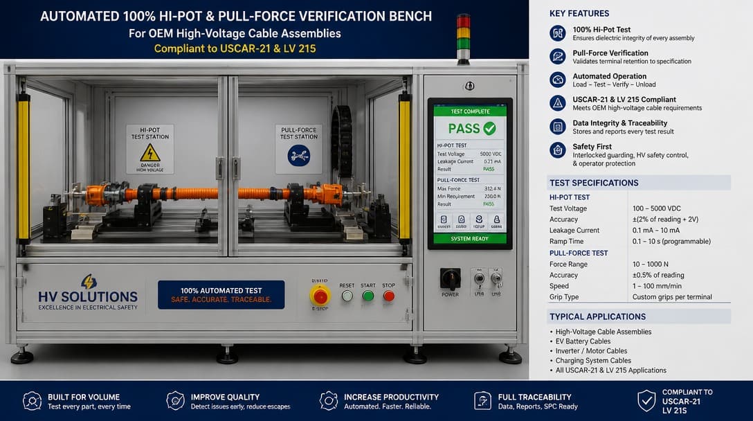
Testing high voltage cable assemblies demands more than a simple go/no-go continuity check. To guard against latent failures that surface only after equipment deployment—weak crimps and invisible insulation breakdown—OEM buyers need to specify mechanical pull force testing aligned with industry standards (such as USCAR-21, SAE J1742, or LV 214/215 for connector crimping, and the ISO 19642 series for automotive high-voltage cables) alongside rigorous Hi-Pot (dielectric withstand and insulation resistance) verification. Continuity testing confirms the electrical path is intact, but it cannot assess mechanical integrity or dielectric strength. Combining all three tests gives a complete picture of a cable assembly’s reliability before it ever reaches the field.
If your cable assembly inspection ends when the continuity tester shows green, you’re catching open circuits and short circuits — but not the two failure modes that cause most field returns. Partnering with an experienced manufacturer that integrates automated mechanical pull-testing and precise Hi-Pot screening as a standard, non-optional protocol on 100% of outgoing shipments is the most effective way for OEMs to close this quality gap starting from the first article sample.
What Your Continuity Test Really Catches (and Misses)
Continuity testing verifies that the intended electrical path exists. A low-voltage signal runs through each conductor, confirming there are no open circuits, short circuits, or miswiring. It’s fast, inexpensive, and effective at catching gross assembly errors—reversed pins, missed terminations, or breaks in the wire.
However, continuity cannot assess the mechanical integrity of a crimp connection or the dielectric strength of insulation. A terminal that is only partially crimped, with strands barely holding, will still pass a continuity test perfectly. Insulation that was nicked during stripping or pinched inside an overmold will also go undetected because the damage does not create a conductive bridge at low voltage. The result is a cable that looks good on paper but is destined for intermittent failure under vibration, thermal cycling, or mild moisture ingress.
IPC/WHMA-A-620, the acceptance standard for cable and wire harness assemblies, explicitly requires both electrical and mechanical verification. Relying solely on continuity contradicts the intent of the standard and leaves the buyer exposed to field returns that are expensive to troubleshoot and even more expensive in terms of brand reputation.
Test Coverage at a Glance: Continuity vs. Pull Force vs. Hi-Pot
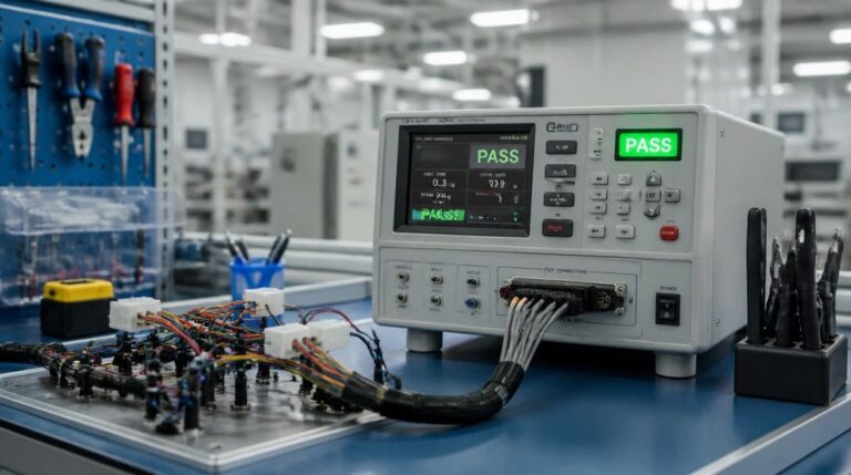
No single test covers all possible failure modes. The table below outlines what each method detects—and what it completely ignores—so procurement and engineering teams can design a credible incoming inspection. Understanding these parameters helps technical buyers leverage advanced high-voltage cable testing instrumentation to establish unambiguous pass/fail boundaries.
| Test Method | Catches | Misses |
|---|---|---|
| Continuity | Open circuits, short circuits, miswiring, reversed polarity | Crimp retention force, insulation dielectric faults, moisture degradation, mechanical wear |
| Pull Force | Crimp tensile strength, terminal retention, wire-to-terminal mechanical quality | Electrical continuity, insulation resistance, dielectric breakdown, intermittency not caused by pull-off failure |
| Hi-Pot (Dielectric Withstand) | Insulation breakdown, clearance/creepage faults, dielectric leakage caused by nicks, contamination, or moisture | Open circuits, intermittent continuity, crimp mechanical quality, miswiring detectable only by continuity |
| HVIL Sequence & Continuity | Misassembled auxiliary pins, incorrect mating sequence (ensuring power contacts connect first/disconnect last) | Main power conductor continuity, main insulation faults, high-current mechanical crimp strength |
| 360° Shielding Resistance | Poor EMI shielding termination, shield-to-shell resistance degradation, braid damage causing EMC compliance failures | Core-to-core isolation, core continuity, non-shielded mechanical and dielectric defects |
For wire harness manufacturing following IPC/WHMA-A-620, all three tests complement each other. A supplier that only performs continuity is effectively shipping assemblies with blind spots that the standard never intended to allow.
High-Voltage Cable Mechanical & Electrical Reference Values
For OEM quality control, relying on generic low-voltage pull charts will lead to field failures. High-current high-voltage (HV) cables use larger cross-sections, which require significantly higher tensile thresholds.
The table below outlines the minimum pull-out forces and typical testing parameters under automotive-grade standards (such as USCAR-21 and LV 215 for terminations) and industrial electrical standards:
| Wire Size (Nominal Cross-Section) | Equivalent AWG | Min. Pull-Out Force (ISO 19642-2 / USCAR-21) | Typical DC Hi-Pot Test Voltage (Automotive / Industrial Spec Baseline) | Max. Allowable Leakage Current Limit | Typical Dwell (Hold) Time |
|---|---|---|---|---|---|
| 2.5 mm² | 14 AWG | ≥ 230 N (51.7 lbf) | 3,000 VDC | ≤ 1.0 mA | 60 seconds |
| 6.0 mm² | 10 AWG | ≥ 450 N (101.2 lbf) | 3,000 VDC | ≤ 1.0 mA | 60 seconds |
| 16.0 mm² | 6 AWG | ≥ 1,500 N (337.2 lbf) | 3,000 VDC | ≤ 2.0 mA | 60 seconds |
| 35.0 mm² | 2 AWG | ≥ 2,800 N (629.5 lbf) | 3,500 VDC | ≤ 2.0 mA | 60 seconds |
| 50.0 mm² | 1/0 AWG | ≥ 3,300 N (741.9 lbf) | 3,500 VDC | ≤ 3.0 mA | 60 seconds |
| 95.0 mm² | 3/0 AWG | ≥ 4,500 N (1,011.6 lbf) | 4,000 VDC | ≤ 5.0 mA | 60 seconds |
How to determine your Hi-Pot test voltage? While low-voltage components traditionally reference the (2U + 1000 V) safety rule of thumb, high-voltage (HV) electrical architectures (typically 600V to 1000V+ DC) must strictly adhere to specialized automotive or industrial connector specifications (such as LV 215, SAE J1742, or UL 2251). For high-voltage systems, the dielectric withstand voltage is typically designated as a fixed value—commonly 2,000 VDC to 3,000 VDC (or a corresponding AC equivalent)—to ensure insulation integrity without over-stressing and permanently damaging the connector’s internal dielectric materials.
Technical Note on Conductor Material: The minimum mechanical pull-out forces listed above are strictly calibrated for stranded copper (Cu) conductors. If your project utilizes aluminum (Al) high-voltage cables for weight and cost reduction, please note that aluminum’s lower tensile strength requires a derating of approximately 25% to 30% in pull thresholds. Always cross-reference the specific terminal manufacturer’s crimp validation specification (e.g., USCAR-21 / LV 214) for the exact aluminum alloy baseline.
Continuity Testing: Necessary, but Never Sufficient
Continuity testing remains a valuable first filter. It instantly identifies assembly mistakes that would cause a dead circuit—a missing connection, a broken wire, a swapped pin. For high-mix, low-volume OEM projects, continuity is often the only electrical check buyers specify on the incoming inspection checklist.
This is precisely where the hidden operational risk lies. Compliant high-voltage manufacturing under IPC/WHMA-A-620 Class 2 and Class 3 protocols demands far more than an uninterrupted electrical path. While Class 2 addresses standard service-life reliability, Class 3 mandates absolute performance under harsh environments where a single failure can lead to thermal runaway or catastrophic system shutdown. A simple green light on a continuity bench cannot differentiate between a low-risk consumer wire and a mission-critical high-voltage powertrain harness.The standard mandates tests that verify crimp force and dielectric withstand precisely because those failures are invisible at low voltage.
Keep continuity in your inspection routine, but never treat it as a final acceptance criterion. It answers “Is the path there?” It cannot answer “Will it stay connected under load?” or “Will it withstand the voltage it’s rated for?” To understand the foundational equipment used to establish these baseline checks, refer to our overview on What Is a Cable Tester and Its Quality Inspection Uses.
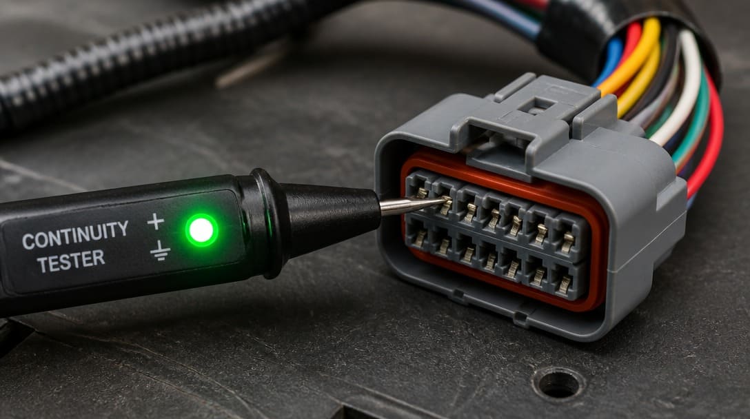
Don’t Let a Green Light Fool You: Upgrade Your Incoming Inspection
If your cable assembly inspection ends at continuity, you are accepting risk that continuity cannot predict. The field returns you see—intermittent opens, arcing, insulation failure—are almost always caused by issues that a comprehensive cable testing strategy would catch.
Top-tier B2B wire harness manufacturers integrate pull-force validation and Hi-Pot screening as standard protocols on every production run rather than treating them as premium add-ons. During your supplier evaluation phase, always demand lot-traceable inspection records—including pull-test statistical reports, actual applied Hi-Pot voltages, measured leakage currents, and exact dwell times. Working with an OEM supplier that provides these verified test datasets out-of-the-box (such as EDOM Electronics’ standard quality loop) mitigates your incoming quality control (IQC) burden and eliminates the risk of field failures.
For custom cable assemblies intended for high-voltage applications, start the conversation at the RFQ stage. Specify the performance class, required pull force values, and hi-pot parameters. Then confirm the supplier has the tooling and test equipment to execute those checks during production—not just on a pre-production sample.
Pull Force Testing: The Crimp Failure Your Continuity Tester Ignores
A crimp terminal can make enough surface-to-surface mechanical contact to pass a continuity test while being structurally unsound. Under the constant vibration, thermal expansion, and mechanical shock of an EV or heavy-duty industrial application, a poorly compressed crimp will degrade rapidly, leading to increased contact resistance, thermal runaway (melting), and eventual electrical open circuits.
While standard low-voltage electronics rely on IPC/WHMA-A-620 Table 19-1 for small wire gauges, high-voltage (HV) power terminations demand strict compliance with heavy-duty automotive standards like USCAR-21, LV 214, or SAE J1742. These specifications account for the unique mechanical behaviors and massive hydraulic/pneumatic forces required to crimp large-gauge copper and aluminum cables (ranging from 2.5 mm² to 120 mm² or higher) to ensure a high-conductivity, low-resistance joint.
For high-voltage applications, passing a simple pull-out force test is still only part of the equation. Leading manufacturers perform Crimp Cross-Section Analysis (Micro-sectioning) during tool setup. By cutting, polishing, and acid-etching the crimped terminal, engineers can microscopically verify the Compression Ratio (which should ideally fall between 15% and 20%). This ensures that all wire strands are deformed into a gas-tight, hexagonal or W-shaped solid mass, eliminating void spaces where moisture could cause galvanic corrosion.
OEM buyers should mandate that their supplier performs destructive pull force verification on a sampling basis (under a defined Acceptable Quality Limit, such as AQL 1.0) at the start and end of every production shift, backed by statistical process control (SPC) charting.
Hi-Pot Testing: Detecting Invisible Insulation Breakdown
Hi-pot (high potential) testing applies an elevated voltage—higher than the operating voltage—between conductors and between conductors and shield to verify the dielectric strength of the insulation system. Damaged insulation, whether from a stripping nick, an overheated shrink tube, or contamination trapped inside a connector, can remain electrically silent until the moment the voltage climbs high enough to arc through the fault.
UL standards often dictate the test voltage and maximum allowable leakage current for specific applications. Medical cables, industrial power harnesses, and EV charging assemblies all reference these requirements to ensure safety. A cable assembly that passes continuity and pull force perfectly can still fail hi-pot instantly if there is a pinhole in the insulation or a strand of wire protruding through the jacket.
Hi-pot testing catches the second major gap that continuity and even pull force miss: latent dielectric faults. Without it, a batch of cables that leaves the factory green-lit can create shock hazards, arc damage, or fire risk in the field. Incorporating hi-pot as a standard part of outgoing inspection turns an invisible threat into a measurable pass/fail criteria.
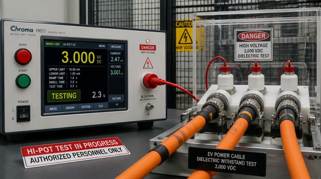
High-Voltage Specific Safety Tests: HVIL and 360° Shielding Continuity
For high-voltage cable assemblies, particularly those used in electric vehicles (EVs) and energy storage systems (ESS), passing dielectric withstand tests is only half the battle. Two high-voltage-specific safety mechanisms require dedicated validation:
1. High-Voltage Interlock Loop (HVIL) Testing
High-voltage connectors feature integrated auxiliary pins that form a low-voltage interlock loop (HVIL). This loop acts as a safety circuit that monitors connector mating state. Under standards such as SAE/USCAR-37, the HVIL pins are physically shorter than the main power contacts, ensuring they connect last during mating and disconnect first during unmating. If the loop is broken, the vehicle’s contactors immediately disconnect high-voltage power to prevent fatal arcing. Suppliers must perform automated HVIL continuity and mating sequence verification during final testing to confirm that the safety-critical timing and loop resistance conform to specifications.
2. 360-Degree Shielding Continuity & Low-Resistance Testing
Because high-voltage lines transfer high-frequency electrical noise from motor inverters, they generate severe electromagnetic interference (EMI). To protect nearby low-voltage sensor lines, these cables utilize a dense 360-degree copper or aluminum braided shield. During final testing, the supplier must verify shielding continuity and measure contact resistance (shield-to-connector shell), typically expecting values in the sub-milliohm range (e.g., ≤10 mΩ). Simply checking the core wires while ignoring the shield-to-shell grounding integrity is a major compliance risk that often results in electromagnetic compatibility (EMC) failures during vehicle certification.
Troubleshooting: Why Did My Cable Assembly Fail Hi-Pot Testing?
When a cable assembly fails hi-pot, the root cause is rarely the tester itself. Instead, one of four common assembly or material issues is usually at play. Diagnosing these quickly reduces rework and keeps production on track.
Cause 1: Physical Insulation Breach and Shielding Braid Slivers
A stripping blade set too deep can score the conductor’s inner insulation jacket, creating an easy path for high-voltage arcing. Similarly, during high-voltage shielded cable termination, the metal braided shield must be cut and folded over an inner ferrule. If individual micro-strands of the copper/aluminum shielding braid are severed and left loose (slivers), they can easily pierce the inner insulation or creep toward the high-voltage terminal pin.
Process monitoring must strictly align with IPC/WHMA-A-620 Section 3 (Wire Preparation and Stripping). To mitigate this risk, OEM buyers should verify that their supplier utilizes programmable rotary stripping machines with dynamic blade compensation rather than manual hand-stripping tools. For the shielding braid termination, top-tier suppliers employ automated inner/outer ferrule crimping combined with pneumatic braid-combing fixtures or automated optical inspection (AOI) to guarantee that 100% of loose slivers are swept away before the final connector housing is assembled.
Cause 2: Moisture or Contamination Trapped in Connectors
Excess flux from hand soldering, humidity absorbed during storage, or cleaning residue can create conductive paths between pins. Even a thin film of moisture will conduct under hi-pot voltage. Check storage conditions and consider oven-drying connectors or assemblies before test. Ensure RoHS-compliant materials are not introducing ionic contamination that increases surface leakage.
Cause 3: Insufficient Clearance or Creepage Distance
If the high-voltage connector selected does not provide enough physical separation over the insulator surface (creepage) or through the air (clearance) for the intended test voltage and expected environmental pollution degree, sparkovers will occur.
When debugging a Hi-Pot failure, engineers should refer to IPC-2221 or IEC 60664-1 to verify if the creepage/clearance design is adequate for the applied peak voltage. Often, a failure at this stage indicates that the design failed to account for moisture or conductive dust in the operating environment, forcing a redesign to a connector with a higher insulation rating or adding specialized high-voltage heat-shrink tubing to extend the creepage path.
Cause 4: Incorrect Test Setup
Test parameters matter. Too fast a voltage ramp can cause a false failure due to capacitive charging. Too short a dwell time may not allow steady-state leakage to settle. Incorrect return connections or unshielded cables can introduce noise. Confirm voltage ramp rate, dwell time, and connection integrity strictly according to the connector manufacturer’s datasheet parameters or high-voltage component-level specifications (such as UL 2251 or LV 215). Additionally, the quality lab must establish a rigid validation schedule to calibrate the hi-pot tester regularly, ensuring threshold accuracy under high-volume production stresses.
From Incoming Inspection to Boxing: What a Complete Quality Loop Looks Like
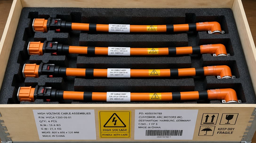
Acceptance testing is just one link in a quality chain that should start at incoming material inspection and end with export-ready packaging. Even cable assemblies that pass continuity, pull force, and hi-pot still need visual inspection for correct labeling, connector orientation, and absence of physical damage. All of that is meaningless if the packaging does not survive international transit—crushed connectors or abrated jackets ruin a good product before it reaches the end user.
A supplier operating under an ISO 9001 quality management philosophy will mandate process controls at every stage: verification of raw materials, in-line crimp height monitoring, final electrical and mechanical testing, and packaging designed for the shipping method. Buyers should look for this holistic approach, not just a final inspection checklist. It is the difference between a manufacturer that catches problems and one that prevents them.
Implementing standard industrial wire harness quality inspection and robust export packaging protocols ensures that high-value electrical sub-assemblies remain immune to environmental hazards from the factory floor to the international loading dock. For mission-critical OEM projects, this end-to-end traceably is non-negotiable.
Frequently Asked Questions
What is the difference between continuity testing and hi-pot testing for cable assemblies?
Continuity testing uses low voltage to verify that an electrical connection exists along a conductor. Hi-pot testing applies a much higher voltage to stress the insulation and detect dielectric breakdown — learn more in our practical guide on what a cable tester does.
Does IPC/WHMA-A-620 mandate mechanical pull force testing for high-voltage heavy-gauge crimps?
Yes. While IPC/WHMA-A-620 defines baseline crimp pull force metrics, critical high-voltage applications require pairing these tensile limits with automotive-grade standards like USCAR-21 to validate large-gauge (up to 95 mm²+) terminal retention under massive mechanical stress.
Why does a high-voltage cable assembly pass low-voltage continuity but fail high-potential (Hi-Pot) testing?
Absolutely. A low-voltage continuity signal easily jumps across a microscopic copper shielding sliver or structural insulation breach without registering a fault. However, when the system is subjected to a 2,000V–3,000V DC Hi-Pot charge, that minor mechanical defect acts as an ionized leakage path, triggering a dielectric breakdown that low-voltage multi-meters are completely blind to.
What should OEM buyers ask suppliers about testing before placing an order?
Buyers should request documentation of pull force test values per IPC/WHMA-A-620 for every connector family and wire gauge, hi-pot test records including voltage, leakage current, and dwell time, and a clear description of what happens to rejected lots. Ask whether these tests are performed on 100% of units or on a sample basis, and whether the supplier’s quality system is built around ISO 9001 principles.
Is hi-pot testing required for all high voltage cable assemblies?
Requirements depend on the application and the standards it must meet. Many UL standards for medical, industrial, and power cabling mandate dielectric withstand testing. Even when not legally required, leading OEMs include hi-pot as a standard practice to prevent latent insulation failures from reaching the field.
OEM Buyer’s Checklist: Auditing a Supplier’s High-Voltage Test Loop
Before signing a high-voltage cable sourcing contract, ensure your manufacturer’s testing laboratory and production line pass this 5-point Poka-Yoke (error-proofing) audit:
- 100% Digital Interlocking (MES Integration): Does the Hi-Pot and HVIL tester automatically talk to the Manufacturing Execution System (MES)? The system must physically lock the fixture or refuse to print the final shipping barcode if a failure is detected.
- Arc Detection Sensitivity: Is the Hi-Pot tester configured for specialized Arc Detection (microsecond current spike monitoring), or does it only check broad milliamperage leakage? (Advanced arc detection is mandatory for catching hidden insulation fissures).
- Calibration and Verification Blocks: Does the operator run a “Daily Golden Sample” (a known failed cable with a controlled insulation defect) at the start of every shift to verify the tester actually catches faults?
- Shielding Resistance Methodology: Is the 360° shielding continuity measured using a true 4-Wire Kelvin Resistance Probe to filter out test lead artifacts and guarantee sub-milliohm accuracy?
- Environmental Traceability: Are the high-voltage connector assembly and testing zones humidity-controlled (typically <60% RH) to eliminate false failures or latent moisture trapping?
Need to Validate Your High-Voltage Testing Specification?
If your current cable harness supplier cannot provide traceable, digitally interlocked Hi-Pot data, or if you are transitioning from copper to aluminum cables and need to recalibrate your USCAR-21 pull force baselines, the engineering team at EDOM Electronics can help.
We integrate automated 4-wire Kelvin resistance screening, cross-sectional micro-imaging, and 100% MES-locked Hi-Pot loops into every OEM project by default.
Get a Free High-Voltage Cable Testing Spec Consultation with Our Engineers
Key Takeaways
- Continuity is Blind to High-Voltage Risks: Low-voltage continuity checks only catch absolute opens or shorts; they completely miss latent dielectric breakdown, crimp tension voids, and electromagnetic shielding termination defects.
- Mandate Spec-Specific Pull Force & Micro-Sectioning: Relying on basic IPC charts for heavy-gauge lines invites thermal failure. OEM buyers must enforce strict compliance with automotive-grade crimp specifications (such as USCAR-21 or LV 214) and demand regular Crimp Cross-Section Analysis to ensure a gas-tight joint with a 15% to 20% compression ratio.
- Calibrate Hi-Pot Voltages and Account for Aluminum Derating: Avoid outdated generic formulas that over-stress insulation. Dielectric withstand test voltages should align with specific connector specifications (typically 2,000V to 3,000V DC). Additionally, if utilizing aluminum high-voltage cables, mechanical pull force thresholds must be derated by 25% to 30% compared to standard copper baselines.
- Audit for Poka-Yoke (Error-Proofing) Testing: A high-voltage cable assembly is only as reliable as the supplier’s process loop. Ensure your manufacturer utilizes 100% digital interlocking (MES integration) to lock out failed units, employs automated rotary stripping to prevent insulation scores, and conducts sub-milliohm 4-wire Kelvin resistance verification on 360° EMI shielding.
For a deeper look at how cable assembly validation connects to export preparation, visit quality inspection and export packaging for OEM-grade requirements.