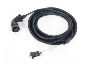
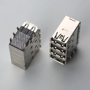
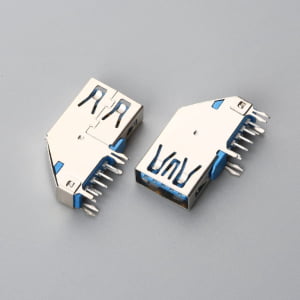
If you’re sourcing a connector from a part number on a drawing and you think matching the pin count and dimensions is enough — this article covers the two things that are invisible from a photo but determine whether the connection will hold.
Executive Summary: Why Visual Connector Inspection Invites Latent Bus-Off Failures
A CAN bus connector is any connector used in a Controller Area Network — a robust serial communication bus common in automotive, industrial automation, and off-highway equipment. But “CAN bus connector” is an application label, not a universal standard. The term may refer to a Molex MX150, a TE DEUTSCH DT, a JST JWPF, an Amphenol M12 A-coded, or a Hirose DF62 series, among others. Matching the part number stamped on a drawing is only the starting point. Two parameters invisible in a photograph — the terminal’s approved wire gauge range and its plating material — determine whether the connection will hold over the life of the equipment. A housing that physically snaps together but uses the wrong terminal for your wire construction will pass a continuity beep and fail in the field.
What Exactly Is a CAN Bus Connector?
Engineers and procurement teams frequently encounter a drawing that lists a connector with a note like “CAN bus connector — 4-pin sealed.” The assumption that follows is dangerously common: that any 4-pin sealed connector from any brand will work, as long as the pin count and mating face look right.
In reality, “CAN bus connector” describes how the connector is used — not what it is. The part number on a drawing typically identifies a specific manufacturer series: a Molex MX150 series, a TE Connectivity DEUTSCH DT series, a JST JWPF series, an Amphenol M12 A-coded connector, or a Hirose DF62 series. Each of these families has a proprietary terminal system, wire seal design, and locking mechanism. They are not interchangeable simply because they share a pin count or a vague visual resemblance (see our detailed guide on CAN bus connector types, pinouts, and wiring basics for exact pin mapping across DB9, OBD-II, and M12 interfaces).
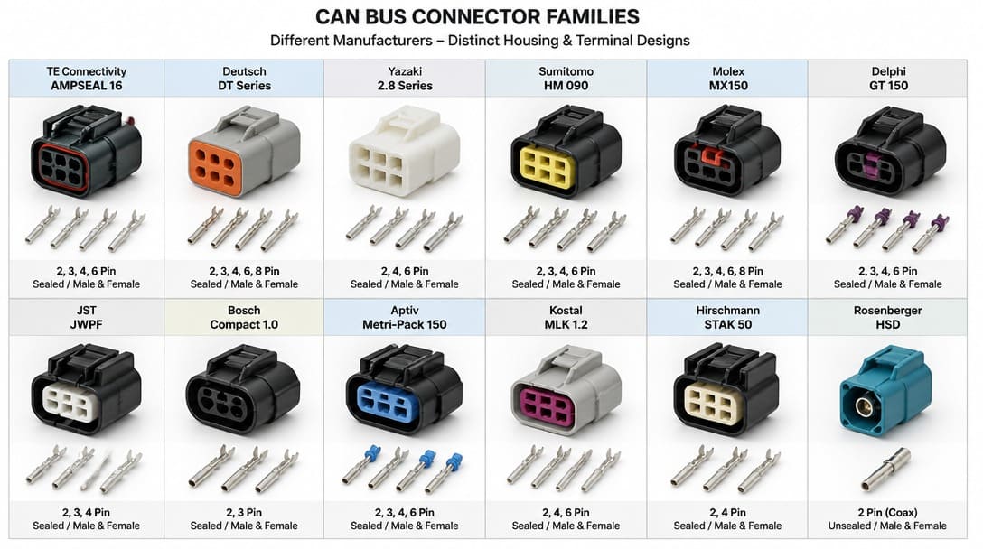
The distinction between brand, series, and generic terminology matters because many engineers use “CAN connector” as shorthand for whatever sealed multi-pin connector happens to appear on the BOM. True interoperability requires matching the exact series and terminal family — not just the footprint. A TE DEUTSCH DT06-4S and a Molex MX150 4-circuit receptacle both have four positions and a sealed interface, but they share no common tooling, terminals, or performance characteristics.
Why Pin Count and Physical Dimensions Alone Cannot Guarantee a Working Connection
Visual confirmation is the weakest form of connector verification. A connector housing may snap cleanly into its mate. The keying may align. A multimeter may beep continuity on all four pins. And the assembly may still fail within weeks of installation.
The problem lies in two parameters that are invisible from any photograph or even from casual physical inspection: the terminal’s approved wire gauge range and the terminal’s plating material.
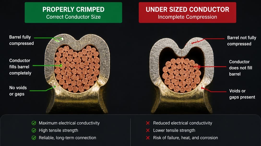
We regularly see incoming shipments of compatible connectors that pass visual inspection but fail crimp pull testing because the terminal barrel was sized for a different wire construction. The part looks right; the physics doesn’t work. A terminal engineered for 18 AWG standard copper conductor will not properly deform around a 22 AWG conductor — the crimp wings bottom out before applying adequate compression, or they fold asymmetrically, creating a high-resistance connection that degrades under thermal cycling.
This is not a hypothetical scenario. It is a recurring pattern in production environments where connectors were sourced based on a photo match or a seller’s description rather than a detailed cross-reference of the manufacturer’s terminal specification against the actual cable construction on the buyer’s drawing.
Wire Gauge, Terminal Barrel, and Insulation OD: The Invisible Compatibility Factors
Every stamped-and-formed terminal is engineered for a narrow wire gauge range — typically spanning two AWG sizes, such as 20–22 AWG or 18–20 AWG. This range is not a suggestion; it is a physical constraint. Crimp height, conductor barrel internal diameter, and the geometry of the crimp wings are all designed around a specific stranded conductor cross-section and strand count.
When a terminal designed for 18 AWG is used with a 22 AWG conductor, the stripped wire will slide into the barrel — and that is precisely what creates false confidence. The conductor enters the terminal, but the crimping tool cannot compress the wings far enough to cold-weld the strands into a gas-tight connection. The result is crimp pull force well below the thresholds defined in EIA-364[1] test procedures, with pull-out values that may pass initial checks but degrade sharply after exposure to vibration.
Equally critical — and equally overlooked — is the insulation outer diameter. The insulation crimp section of the terminal must grip the wire’s insulation without crushing it or leaving it loose. If the insulation OD is too small, the terminal may not be adequately retained in the housing cavity; if too large, it will not fit inside the cavity at all, or it will distort the terminal’s alignment with the mating pin.
Before placing any order, the connector manufacturer’s datasheet must be cross-referenced against the actual cable specification. The data to check: approved wire gauge range in AWG or mm², approved insulation OD range, and — for sealed connectors — compatibility with the housing’s wire seal inner diameter.
Tin Plating vs. Gold Plating: Which One Should You Choose for a CAN Bus Environment?
Terminal plating is the second invisible parameter that determines long-term connector reliability. The choice between tin and gold is not cosmetic; it directly affects contact resistance stability, mating cycle durability, and corrosion resistance in the target environment.
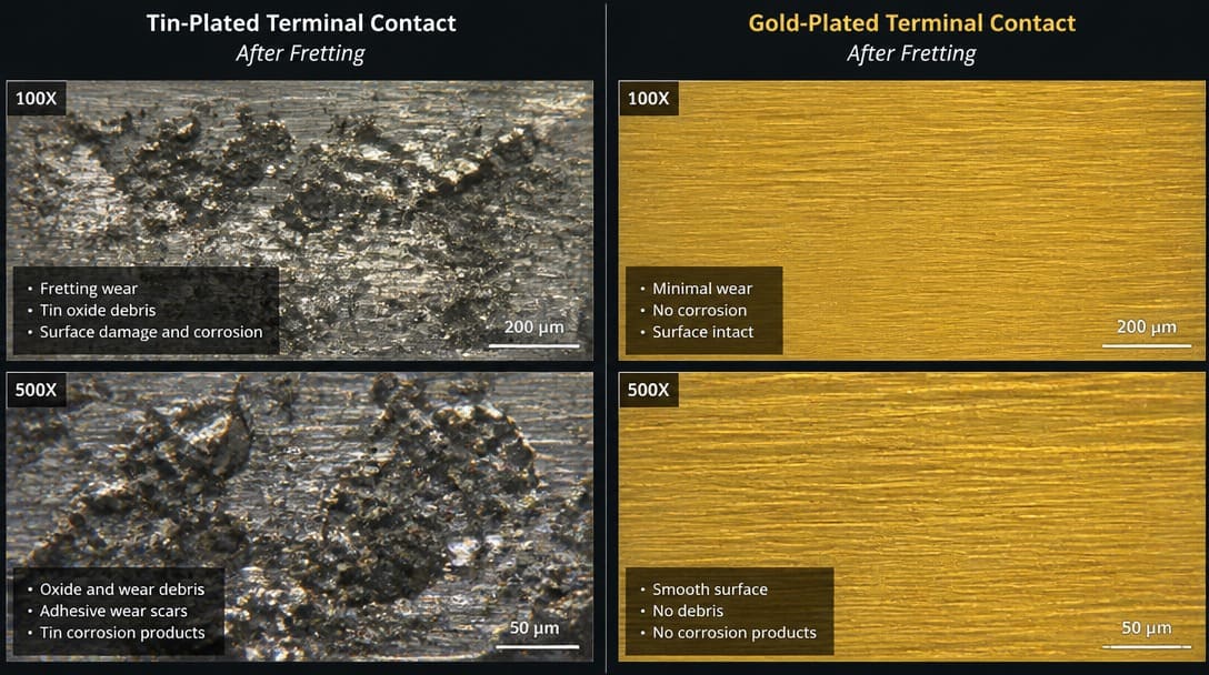
Tin plating offers a low-cost, RoHS-compliant finish that performs adequately in dry, low-vibration, low-cycle applications. However, tin is susceptible to fretting corrosion — the micro-motion at the contact interface that gradually builds an insulating oxide layer. In engine bay harnesses, chassis-mounted connectors on off-highway equipment, or any location subject to continuous vibration, tin-plated terminals can develop increasing contact resistance over time, eventually causing intermittent CAN bus communication faults that are notoriously difficult to diagnose.
Gold plating, typically applied over a nickel underlayer, provides stable low contact resistance across hundreds of mating cycles and resists corrosion in damp, variable-temperature conditions. For CAN bus networks in construction machinery, agricultural equipment, or marine applications — where connectors may be unplugged for service or exposed to condensation — gold-plated terminals reduce the long-term risk of signal degradation.
| Parameter | Tin Plating | Gold Plating (over Nickel) |
|---|---|---|
| Typical mating cycles | 25–50 before significant oxidation | 100–500+, depending on gold thickness |
| Fretting corrosion resistance | Low — susceptible in vibration environments | High — stable under micro-motion |
| Cost relative to tin | Lower | Higher — gold thickness drives cost |
| Recommended environment | Dry, low-cycle, sealed enclosures | High-vibration, humid, frequent mating |
| RoHS compliance | Yes | Yes |
The decision is not always clear-cut. A gold-plated terminal in an IP67 sealed connector used inside a climate-controlled industrial cabinet is unnecessary cost. A tin-plated terminal in an unsealed connector mounted on a tractor chassis is a latent failure that may surface only after years of field operation. The connector datasheet’s durability rating and environmental test sequence should be the guide, not a default preference for either material.
Compatible vs. Interchangeable: What’s the Real Difference?
The words “compatible” and “interchangeable” are used loosely in connector sourcing — often to the buyer’s disadvantage. The distinction carries real engineering weight, and treating them as synonyms leads to qualification gaps.
A compatible connector is one that physically plugs into the mating half and establishes electrical continuity on all pins. It may share the same housing profile and keying code. However, compatibility does not guarantee that the connector meets the same electrical, mechanical, or environmental specifications as the original. The terminal retention force may be lower. The plating thickness may differ. The sealing class may not match. The connector passes a continuity check but has not been verified to the full performance envelope of the OEM part.
Interchangeability is a higher standard. It requires that every functional dimension, material property, and performance characteristic — from terminal insertion force to IP rating to vibration withstand — be identical to the specified component. Achieving true interchangeability demands full qualification testing, not just dimensional inspection.
Many aftermarket connectors marketed as “compatible with Molex MX150 series” or “replacement for TE DEUTSCH DT” use terminals with thinner plating, shorter conductor barrels, or slightly different base materials. The mated pair will beep on a continuity tester. It will not survive a full vibration test sequence. When a drawing specifies a manufacturer part number, any substitution should be treated as an engineering change requiring the same validation rigor as the original component selection.
CAN Bus Connector Verification Checklist: What to Confirm Before You Order
The time to catch a terminal mismatch is not during first-article inspection — it is before the purchase order is issued. The following checklist covers the minimum verification steps that procurement teams and design engineers should complete when a CAN bus connector appears on a drawing or BOM.
- Confirm the approved wire gauge range. Cross-reference the connector manufacturer’s datasheet — not a distributor’s website description or a seller’s listing — against the actual AWG or mm² of the wire specified on the drawing. Ensure the terminal is designed for that gauge, including strand count if detailed.
- Confirm the insulation OD. The wire’s insulation outer diameter must fall within the terminal’s insulation crimp range and, for sealed connectors, the housing’s wire seal inner diameter. A mismatch here can prevent terminal insertion or compromise the seal.
- Verify the mating interface geometry. Do not rely on visual similarity. Compare the part number, series designation, and keying code against the mating connector on the device. A 4-pin Molex MX150 receptacle is not a 4-pin Amphenol AT Series receptacle.
- Match the terminal plating to the operating environment. Assess the expected mating cycle count, vibration exposure, humidity, and temperature range. Select tin or gold plating accordingly, and confirm RoHS compliance if required for the target market.
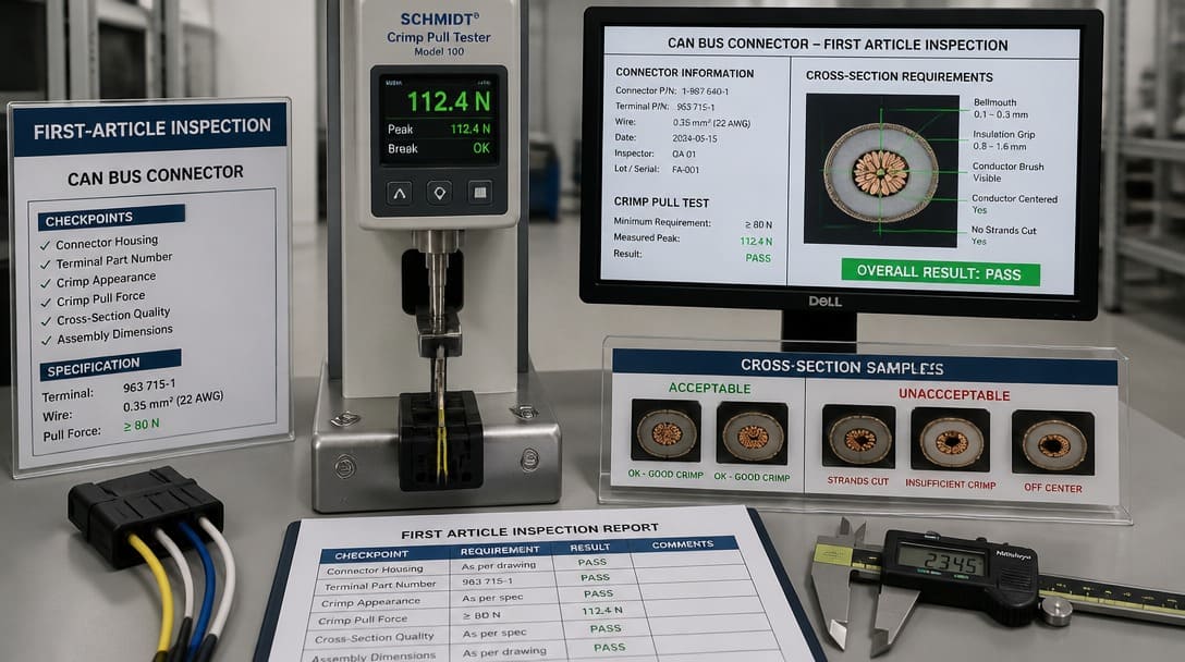
- Request production-representative samples. Before committing to a volume order, obtain samples built with the exact terminal, wire, and seal combination specified. Perform first-article crimp pull testing. Cross-section at least one crimp sample to verify conductor compression.
Many wire harness manufacturing programs stall at this stage because buyers treat the connector as a commodity part and the terminal as an afterthought. A verified terminal-to-wire combination is the only proof that the connection will survive production handling and field service.
Next Steps: From Verification to Reliable Sourcing
Once the correct connector series, terminal part number, and plating option have been identified and verified against the wire specification, the challenge shifts to finding a consistent supply of validated components — not look-alike parts that drift from lot to lot.
For OEM buyers managing multiple custom cable assembly projects, the connector verification process described above applies to every part number on the BOM. A single unverified terminal substitution can introduce a failure mode that escapes end-of-line continuity testing and surfaces only months later as an intermittent CAN bus node error.
Suppliers such as EDOM Electronics support OEM buyers with requirement review, connector matching, sample coordination, production follow-up, inspection, and export-ready packaging for custom cable assemblies and wire harnesses. This type of support is especially valuable when navigating multi-source connector BOMs where terminal families, plating options, and wire gauge ranges must all be reconciled before production release. The quality inspection and export packaging process ensures that what arrives on the dock matches what was validated during first-article approval — a non-negotiable requirement when connector performance is safety or mission critical.
For further guidance on connector families, mating interfaces, and application matching, explore the electronic connectors resource center — a practical reference for OEM buyers and design engineers working through connector selection and sourcing decisions.
Frequently Asked Questions
Can I use any 4-pin sealed connector for a CAN bus network?
No. While many 4-pin sealed connectors share similar external dimensions, they are proprietary designs from manufacturers such as Molex, TE Connectivity, JST, Amphenol, and Hirose. The terminal system, wire seal, locking mechanism, and performance characteristics differ. Only the exact series and part number specified on the drawing should be used unless a full engineering review confirms a verified substitute.
What happens if I use a terminal designed for a different wire gauge?
A terminal engineered for a specific wire gauge range — for example, 18–20 AWG — will not form a reliable crimp on a 22 AWG conductor. The crimp wings cannot compress enough around the smaller conductor, resulting in low pull force, high electrical resistance, and eventual connection failure under vibration or thermal cycling. This failure mode may not appear during a simple continuity check at end-of-line testing.
Is gold plating always necessary for CAN bus connectors?
Not always. Gold plating is recommended for high-vibration environments, humid conditions, applications with frequent mating cycles, or unsealed connectors exposed to corrosion risk. Tin plating is suitable for dry, low-cycle, sealed applications where cost is a priority. The decision should be based on the connector datasheet’s durability rating and the specific environmental conditions of the application — not on a blanket assumption that gold is “better.”
How can I tell if a replacement connector is truly interchangeable?
True interchangeability requires that every functional dimension, material, and performance parameter match the original OEM component. This includes terminal design, plating material and thickness, sealing class, retention force, and electrical ratings. A supplier’s claim of “compatible” should be backed by test data for the full performance envelope, not just a continuity check. If the drawing specifies a manufacturer part number, treat any substitution as an engineering change requiring formal qualification.
What should I ask a supplier before ordering CAN bus connectors for a new production build?
Request the manufacturer’s official datasheet for the specific connector and terminal part numbers. Confirm the approved wire gauge range and insulation OD range directly from the datasheet. Ask whether the supplier can provide production-representative samples for first-article crimp pull testing. For sealed connectors, confirm that the wire seal matches the specified wire OD. Verify RoHS compliance and lead time for the exact terminal plating option required.
Key Takeaways
- “CAN bus connector” is an application label, not a universal product category — the part number on a drawing identifies a specific manufacturer series from brands such as Molex, TE Connectivity, JST, Amphenol, or Hirose, and true interoperability requires matching that exact series and terminal family.
- Pin count and housing dimensions alone cannot guarantee a working connection; the terminal’s approved wire gauge range and insulation OD range are the invisible parameters that determine whether the crimp will hold over the life of the equipment.
- Terminal plating — tin versus gold — is a reliability decision, not a cosmetic one, and must be matched to the application’s vibration exposure, mating cycle expectation, and environmental conditions.
- A connector labeled “compatible” is not the same as one that is “interchangeable” — compatibility often means only physical fit, and substitution without full qualification introduces risk that continuity checks cannot detect.
- Verifying the connector datasheet against the actual wire specification before ordering — including gauge, insulation OD, plating, and mating interface — is the single most effective step an OEM buyer can take to prevent field failures in CAN bus networks.
Explore our electronic connectors resource center for detailed guidance on connector families, terminal systems, and application matching for OEM and industrial projects.