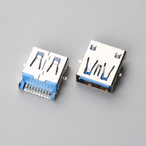
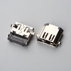
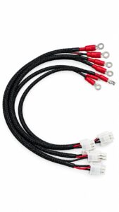
A design engineer opens a component library and sees rows of connector footprints—D-Sub 9, USB-C, M12. Without understanding that a connector is more than a plastic shell and metal pins, the first pro…
Direct Answer
A connector is an electromechanical component that joins two or more conductors to form a separable electrical circuit. It provides three inseparable functions: a low-resistance current path, mechanical alignment that maintains contact force, and environmental protection appropriate to the operating conditions. For OEM buyers, a connector is defined not by its plastic housing but by its contact material, plating, termination compatibility, and retention mechanism—all of which must be validated against the assembly process and field environment before ordering.
At a Glance
An electronic connector creates a controlled interface between wires, printed circuit boards, or devices. Its performance depends on material choices and manufacturing tolerances that are invisible in a catalog photo. Contact base metal, plating thickness, termination type, and locking mechanism determine whether the connection stays electrically stable after repeated mating, vibration, and environmental exposure. A connector specification is never complete until the buyer confirms that the wire gauge, PCB footprint, or cable structure matches the contact’s engineered range, that the plating meets the mating cycle requirement, and that the retention method suits the installation environment.
What a Connector Actually Does: Electrical, Mechanical, and Environmental Roles
A connector is not a passive piece of plastic and metal. It actively manages current flow, physical stress, and environmental exposure at a circuit interruption point. The electrical role is to establish a stable, low-resistance path between conductors—whether carrying millivolt sensor signals or double-digit amperage to a motor drive. Contact resistance must remain consistent across the product’s service life, even as the connector experiences thermal expansion, vibration, and repeated plugging and unplugging. When selecting power interfaces, engineers must verify electrical limits under actual circuit dynamics—see our engineering guide on DC connector rating vs AC connector derating to evaluate continuous carry versus breaking capacity for 48V DC substitutions.
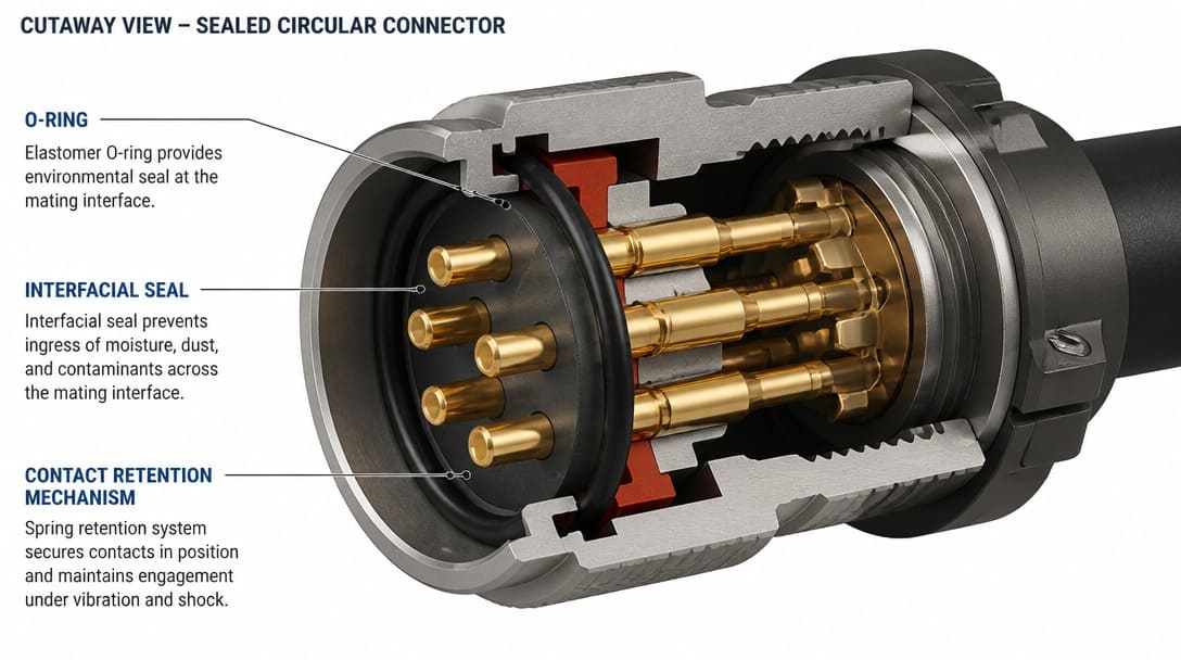
The mechanical role is alignment and retention. The housing guides the contacts into precise engagement, while the contact spring design maintains a defined normal force against the mating surface. If that force relaxes over time—due to metal fatigue or thermal cycling—the resistance rises, and intermittent failures begin. Environmental protection is the third role. A connector may need to exclude dust, resist salt spray, or survive a direct water jet, quantified by IP ratings such as IP67 or IP68. Sealing is achieved through gaskets, O-rings, or interfacial seals integrated into the housing and mating interface.
Breaking Down a Connector: What Datasheets Actually Describe
Datasheets for connectors from suppliers such as Molex, TE Connectivity, JST, Amphenol, and Hirose organize specifications around five structural layers. Each layer has consequences for production and field reliability.
Housing
The housing is not merely a plastic shell. It is an insulator that positions contacts at a precise pitch while providing dielectric isolation between adjacent circuits. Common materials include glass-filled thermoplastic and liquid crystal polymer (LCP), chosen for their dimensional stability during soldering and resistance to tracking. The housing material must meet the flammability rating required by the end product, often UL 94[1] V-0 for industrial and medical equipment.
Contact Material
Contacts are stamped and formed from copper alloys—brass, phosphor bronze, or beryllium copper—each offering a different balance of conductivity, spring strength, and cost. Phosphor bronze provides good fatigue resistance for connectors that experience frequent mating. Beryllium copper delivers the highest spring performance but at a higher material cost. The base alloy determines the contact’s current-carrying capacity and its ability to maintain normal force over repeated cycles.
Plating
Plating is the critical interface layer. robust nickel underplate serves as a critical diffusion barrier—preventing copper or zinc from the base metal from migrating into the outer gold layer—while providing a hard mechanical substrate to reduce wear. The primary corrosion resistance is provided by the outer noble plating (like gold). The outer gold or tin finish determines the connector’s mating durability, corrosion resistance, and solderability. To comply with the RoHS directive, tin finishes must be lead-free. However, pure lead-free tin introduces a high risk of catastrophic short circuits due to tin whiskers. Reputable manufacturers mitigate this by utilizing matte tin plating over a robust nickel underplate. Gold thickness—flash, 15µ”, or 30µ”—directly governs how many mating cycles the connector can sustain before wear exposes the nickel underplate. The EIA-364 series of test standards defines the environmental and durability test sequences that validate these plating systems.
Termination Type
How the wire or PCB trace connects to the contact is a manufacturing decision, not an afterthought. Crimp contacts, solder cups, insulation displacement (IDC), and compliant press-fit pins each require specific tooling, process controls, and compatibility checks. A full discussion of termination compatibility follows in the next section.
Retention and Locking
The method that keeps the connector mated—friction, latch, screw-lock, or bayonet—is a system-level reliability decision. A connector that disconnects because it was only friction-fit in a high-vibration enclosure creates the same field failure as one that corroded.
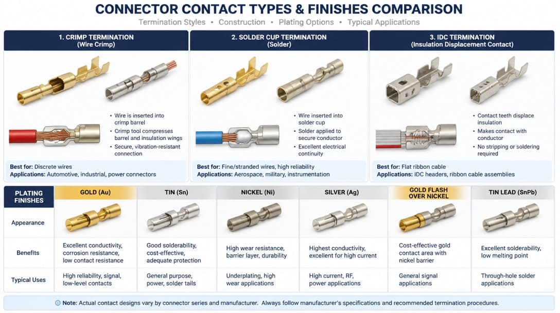
Termination Methods and Why Wire Gauge Compatibility Is Non-Negotiable
Termination is where the connector design meets the assembly process. A mismatch here is the most common cause of production-line rejection and latent field failure, and it cannot be detected by visual inspection alone.
Crimp contacts have a specific wire barrel size range. A contact designed for 22–18 AWG stranded wire will not form a gas-tight crimp on 26 AWG conductors. Furthermore, even if the conductor AWG matches, a mismatch in the wire’s insulation outer diameter (OD) will cause the insulation crimp wings to either pierce the jacket or fail to provide strain relief, leading to premature field failures under vibration.The crimp die set, the contact, and the wire must be engineered as a system. Solder cup terminations require the cup’s inner diameter to match the stripped conductor diameter; an oversized cup produces cold solder joints with poor fillet formation. IDC contacts force the conductor into a slotted beam, displacing insulation in a single press. The IDC slot width is engineered for a precise internal conductor wire gauge (AWG), while the outer housing geometry accommodates a specific insulation thickness to provide proper strain relief.—deviate from either, and the connection is unreliable.
In our factory, we have received connectors that looked identical to the approved sample but could not be crimped because the contact’s wire barrel was sized for a gauge two steps smaller than the assembly print called for. The connector was right; the tooling knew it was not. This is why verifying termination compatibility against the actual cable specification, not just the connector part number, belongs at the top of every procurement checklist.
The TCO (Total Cost of Ownership) Factor for Buyers
Beyond physical compatibility, OEM buyers must weigh the hidden manufacturing costs. Specifying a connector without verifying if your Contract Manufacturer (CM) owns the matching applicator tooling can unexpectedly inflate your Non-Recurring Engineering (NRE) costs.
| Termination Method | Upfront Tooling Cost | Ideal Production Volume | Key Sourcing Risk |
|---|---|---|---|
| Solder Cup | Low (Standard irons) | Low Volume / Prototypes | High manual labor cost; cold joints. |
| Crimp | High (Custom applicators) | High Volume | Wire gauge/die mismatch causing pull-test failures. |
| IDC | Medium to High | Medium to High Volume | Precise insulation diameter requirement. |
For OEM projects where the cable structure and connector must be matched early in the design phase, working with a supplier that reviews drawings and coordinates custom cable assembly can prevent these mismatches before tooling investment begins.
Contact Plating: Gold Thickness, Nickel Underplate, and Real Mating Cycle Limits
Plating is invisible in a photograph but dominant in determining connector life. The gold layer on a contact exists primarily to protect the nickel underplate from oxidation. Flash gold—a few microinches thick—can wear away in fewer than 50 mating cycles, exposing the nickel. Once nickel is exposed and the environment contains sulfur-bearing gases or humidity, contact resistance begins to climb.
Depending on the contact geometry, normal force, and base material, a standard 30µ” gold plating over nickel typically provides 500 to 1,000 mating cycles for traditional industrial connectors (evaluated under EIA-364-09 standards). However, highly engineered interfaces—such as those detailed in our USB-C Connector OEM Guide—utilize optimized receptacle designs and robust palladium-nickel underplates to push that same 30µ” specification beyond 10,000 cycles.A 15µ” gold thickness covers many telecom and consumer applications where the connector is mated a handful of times during its service life. The nickel underplate is the true corrosion barrier; without it, copper alloy contacts tarnish and oxidize even under a gold surface through pores in the gold layer. Tin-plated contacts are widely used in cost-sensitive applications. To comply with RoHS directives, these finishes must be completely lead-free. Furthermore, for long-term reliability, reputable manufacturers specify matte tin over a nickel underplate rather than bright tin; this specific combination mitigates the risk of tin whisker formation, preventing latent short circuits in the field. When evaluating whether to downgrade from gold to tin for BOM cost reduction, buyers must compare normal force thresholds and oxide stability—see our engineering breakdown on connector plating gold vs tin contact resistance to evaluate dry-circuit voltage limits and fretting corrosion risks before changing drawings. Beyond macro-corrosion, repeated thermal cycling and vibration induce interface micro-motion, making it critical to prevent terminal plating fretting corrosion that causes intermittent open circuits inside the wipe track. The plating system also affects solderability: poor wetting during assembly due to oxidized or thin plating can produce marginal solder fillets that fail inspection criteria defined in IPC-A-610 for acceptable solder joint geometry.
| Plating Type | Typical Thickness | Mating Cycles (Approximate) | Common Applications |
|---|---|---|---|
| Flash Gold over Nickel | 1–5 µ” Au | Under 50 | One-time connections, consumer electronics |
| 15 µ” Gold over Nickel | 15 µ” Au, 50+ µ” Ni | 100–500 | Telecom, instrumentation, moderate durability |
| 30 µ” Gold over Nickel | 30 µ” Au, 50+ µ” Ni | 500–1,000+ | Industrial, military, high-reliability |
| Matte Tin over Nickel | 100–300 µ” Sn | 25–100 | Automotive, appliance, cost-sensitive |
Mechanical Retention: How a Connector Stays Mated Under Real Conditions
Friction-fit retention, the most basic method, relies on contact normal force and housing interference. It works in stationary, low-vibration environments such as inside a desktop enclosure. But on machinery, in vehicles, or in any application where cables are routed across moving structures, friction alone is insufficient.
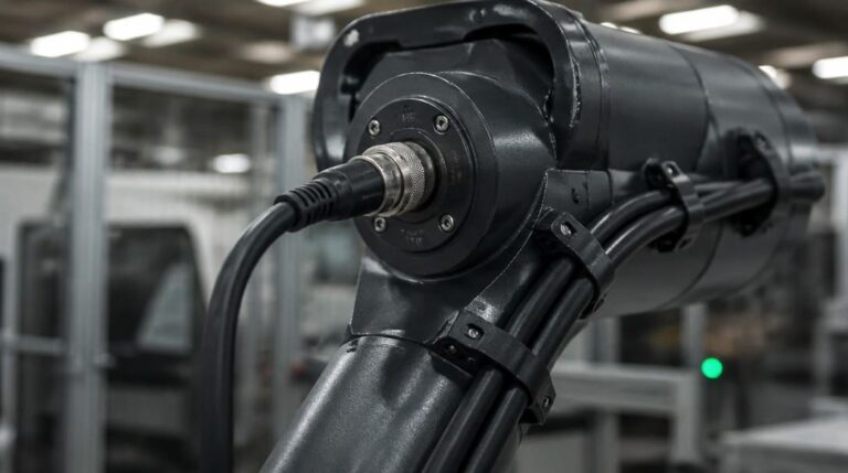
Latch and ramp-lock mechanisms—common in Molex Mini-Fit Jr. and JST XH series connectors—provide a positive lock with an audible click. The user must depress a release tab to disconnect, preventing accidental unmating. Screw-lock and bayonet couplings, used extensively in Amphenol MIL-DTL-style circular connectors and certain Hirose HR series designs, deliver high retention force and sealed interfaces. They also protect the connection from cable pull and twist forces that would otherwise transmit directly to the contacts. Retention force must be evaluated alongside strain relief design; a strong lock is ineffective if the cable jacket can pull the conductor out of the crimp barrel.
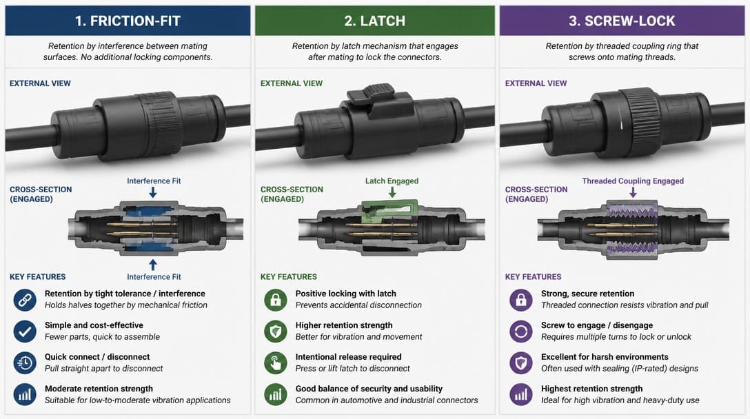
Connector Series Names: Brand-Specific, Generic, and Industry Standards
A connector series name carries specific engineering meaning. TE Connectivity MATE-N-LOK, Molex Mini-Fit Jr., and JST XH are brand-defined families with controlled specifications, proprietary tooling, and traceable test data. Generic equivalents may claim compatibility with these series, but cross-mating a generic housing with a branded contact—or vice versa—can produce mechanical engagement without electrical reliability. The plastic fits; the plating, spring force, and dimensional tolerances differ.
Industry-standard footprints operate differently. D-Subminiature, RJ45, and USB connectors are governed by formal standards bodies and consortiums, ensuring interoperability across vendors. Understanding whether a series name indicates a brand-controlled ecosystem or a true multi-source standard is essential for procurement. It determines whether second-source options exist and what level of interchangeability can be expected in production.
Pro Tip: The Danger of Generic Naming
The gap between a generic name and an industry standard is best illustrated by the VGA connector. Buyers requesting a standard “15-pin VGA” often end up with a physically incompatible DB15 instead of the required high-density DE-15. Always verify the exact footprint standard behind the common name.
Environmental Sealing and Ingress Protection in Connectors
Environmental protection is not an accessory—it is part of the connector design. IP ratings such as IP67 (dust-tight, protected against temporary immersion) or IP68 (dust-tight, protected against continuous immersion under specified conditions) require the connector housing, mating interface, and cable entry to form a complete seal. This is achieved through O-rings, gaskets, interfacial seals, and cable gland entries made from silicone or EPDM.
Sealed connectors demand higher insertion force and often require a mating enclosure that matches the connector’s sealing face. An IP67-rated connector installed in an unsealed enclosure provides no environmental protection to the system. Outdoor, washdown, and marine applications routinely require sealed connectors with robust strain relief and corrosion-resistant hardware. The selection of sealing materials must account for chemical exposure, UV degradation, and the temperature range of the service environment.
Connector Verification Checklist Before You Order
The following checklist transforms awareness into procurement discipline. Address each point before releasing a purchase order or committing to tooling.
- Confirm termination method compatibility. Check the contact’s wire gauge range, solder cup inner diameter, or IDC slot width against your actual cable specification or PCB land pattern.
- Verify plating. Note gold thickness and nickel underplate. Cross-reference with mating cycle requirement and environmental exposure using EIA-364 test plan references in the supplier’s qualification data.
- Check key dimensions. Compare the supplier drawing, a physical sample, or a verified 3D model. Evaluate not only the outline but the mating interface depth, backshell clearance, and panel cutout. When qualifying alternative parts or second-source components, outline dimensions alone are never sufficient—follow our engineering guide on verifying connector compatibility beyond pin count to audit crimp tooling, plating, and contact derating before signing off on a substitute.
- Confirm mating cycle rating. Ensure the connector’s rated cycles exceed the expected in-service connection and disconnection count, including test and maintenance.
- Validate material conformity. Housing resin must meet UL 94 flammability requirements for the end product. Contact base material must suit the current-carrying capacity. All materials must be RoHS-compliant if required by the target market.
- Inspect retention and locking. Will the mechanism—friction, latch, screw-lock, or bayonet—withstand the vibration, shock, and cable strain of the installed location?
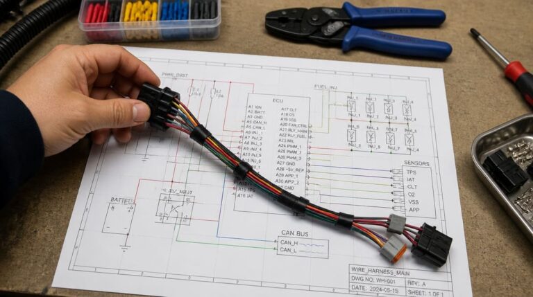
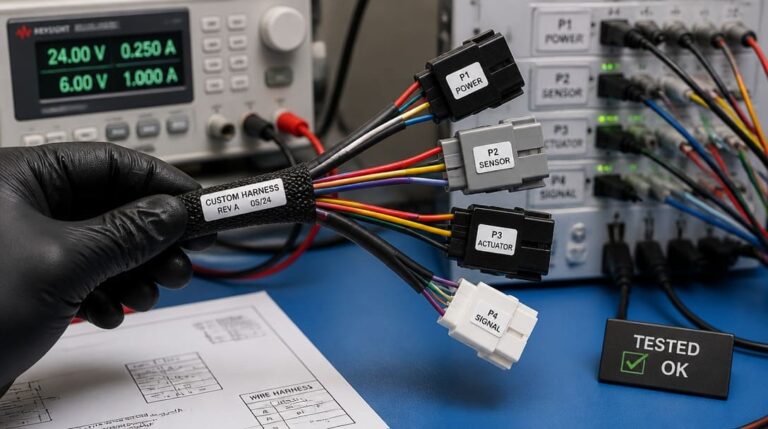
These verification steps are particularly important when the connector feeds into a larger wire harness manufacturing process, where a single unverified termination spec can stall an entire production run. Equally, the final quality inspection and export packaging stage cannot catch a plating or termination mismatch that was baked into the specification at the ordering stage.
From Verification to Production: Moving from a Part Number to a Stable Supply
When the checklist reveals gaps—unclear plating thickness, missing tooling compatibility data, or an IP rating that does not match the enclosure design—those gaps must be closed before tooling investment. Working with a production-coordinated supplier that reviews drawings, validates connector specifications against the assembly process, and coordinates samples can prevent the most common sourcing failures.
Suppliers such as EDOM Electronics support OEM buyers with requirement review, connector matching, sample coordination, production follow-up, and export-ready packaging. This approach ensures that the connector specified in the design file is the connector that arrives on the production floor—and that the assembly process is equipped to terminate it correctly.
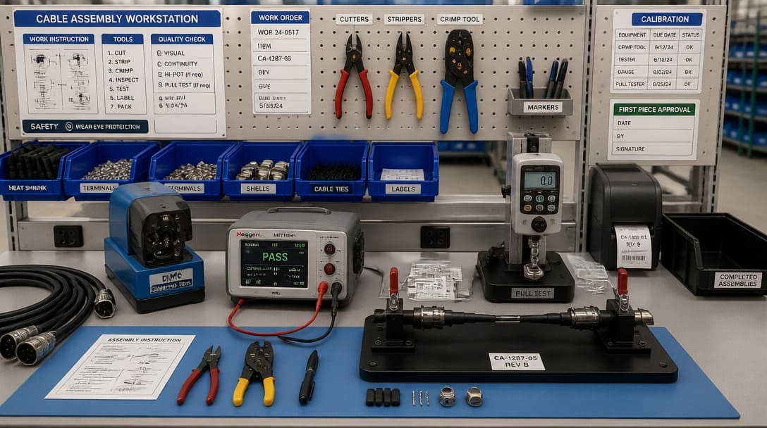
Connector Families to Explore Next
A connector is not a single category. The following connector families each have distinct termination, sealing, and retention characteristics that determine where they fit in an OEM design. Understanding the differences enables specification from first principles rather than by catalog browsing.
- USB-C connectors: Reversible, high-speed data and power delivery; common in modern consumer and industrial equipment with USB PD requirements.
- BNC connectors: Bayonet-lock RF connectors for test equipment, broadcast, and video applications where impedance matching is critical.
- XLR connectors: Professional audio connectors with latch lock and dedicated shield ground pin; standard in stage, studio, and installed sound.
- PCB & Wire-to-Board Connectors: Board-to-board and wire-to-board interfaces for internal power and signal distribution. To avoid costly tooling delays when specifying crimp-style lines, read our complete guide on what is a JST connector, common series, pinouts, and applications, or check our engineering comparison on JST connector pitch 2.50mm vs 2.54mm key differences to prevent footprint mismatch across high pin counts.
- DC Connectors (Barrel Plugs & Power Jacks): Standardized and vendor-defined coaxial barrel interfaces for low-voltage DC power delivery. To avoid loose center pin contacts, intermittency, and polarity mismatches in OEM designs, refer to our comprehensive guide on what is a DC connector, barrel types, polarity, and uses.
- Pigtail Connectors (Flying Leads): Single-ended assemblies with a terminated interface on one side and stripped/tinned leads on the other, commonly used for sensor integration and enclosure-to-board transitions—read our guide on what is a pigtail connector and key OEM specs to prevent BOM-level RFQ delays.
- RCA connectors: Legacy audio/video connectors with friction-fit ground contacts; still present in test setups and consumer equipment.
- DVI Connectors: Essential display interfaces for industrial automation, medical equipment, and legacy embedded systems.
- SATA Connectors: Standard high-speed storage interfaces widely used in industrial PCs, embedded computing, and enterprise servers.
- RJ45 Connectors: Standardized 8P8C modular interfaces primarily used for Ethernet and high-speed data transmission in telecommunications, industrial automation, and networking equipment.
- D-Subminiature (DE 9 / DB9): The standard for RS-232 serial and CAN bus communication in industrial automation.
- Banana Connectors: Generic 4mm or 2mm single-wire interconnection systems with a spring-loaded male pin and matching socket, commonly used for test leads, bench instruments, and temporary panel connections.
To see how these connector families are selected in practical wire harnesses, explore what connectors are commonly used in custom cable assemblies for real-world category breakdowns.
For deeper selection guidance, pinout details, and application notes on each family, visit the electronic connectors resource page.
Uncertain About Your Connector BOM?
Don’t let a hidden plating or termination mismatch halt your production line. Send us your drawing or part number. Our engineering team provides a Free Connector BOM Review & Cross-Reference Verification to ensure process compatibility and uncover potential cost-saving alternatives. Get Your Free Verification Now
Frequently Asked Questions
What is a connector in electronics?
A connector is an electromechanical component that joins two or more conductors to form a separable electrical circuit. It provides electrical continuity, mechanical alignment, and environmental protection as an integrated system—not just a plastic plug and socket.
Why do two connectors that look the same perform differently?
Differences in contact base metal, plating thickness, and housing resin are invisible in photographs. A connector with flash gold and no nickel underplate looks identical to one with 30µ” gold over nickel but fails after a fraction of the mating cycles. Physical dimensions do not capture material quality or process specifications.
What happens if I use the wrong wire gauge with a crimp contact?
The crimp will fail either mechanically or electrically. An undersized wire in an oversized barrel will not achieve the cold-weld compression required for a gas-tight joint. An oversized wire will damage the barrel, crack the contact, or produce high resistance. The wire gauge must fall within the contact’s specified barrel range.
How do I know if a connector supplier supports production coordination?
Ask whether the supplier reviews drawings and BOMs before quoting, provides sample confirmation, coordinates connector matching with the cable structure, and follows up with in-process inspection and export-ready packaging. Suppliers such as EDOM Electronics offer these coordination services for OEM buyers sourcing custom cable assemblies and wire harnesses.
What standard governs connector durability testing?
The EIA-364 series of standards, maintained by the Electronic Components Industry Association, defines test procedures for connector durability, corrosion, thermal shock, and mechanical shock. Buyers should reference EIA-364 test plans when evaluating supplier qualification reports for plating and mechanical performance claims.
Key Takeaways
- A connector is defined by its contact material, plating, termination type, and retention mechanism—not by its external shape or a catalog photo.
- Termination compatibility with the actual wire gauge or PCB footprint is the single most common failure point in connector sourcing and cannot be verified by visual inspection.
- Gold plating thickness and nickel underplate directly determine mating cycle life; flash gold can wear through in fewer than 50 cycles, while 30µ” gold can exceed 1,000 cycles under EIA-364 test conditions.
- Connector series names from Molex, TE Connectivity, JST, Amphenol, and Hirose carry specific engineering specifications; generic equivalents may mechanically fit but differ in plating, resin, and contact performance.
- A disciplined verification checklist—confirming termination range, plating, dimensions, cycle rating, material compliance, and retention—must be completed before releasing a purchase order.
For selection guidance across connector families and to explore production-coordinated sourcing support, visit the electronic connectors resource page.