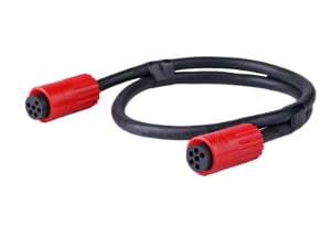
If you’re designing a new product or tasked with sourcing a connector for an assembly and you find yourself searching “what connectors” — this guide moves you from vague need to a spec you can confidently order against, without missing the manufacturing details that cause field failures.
Before selecting specific harness connectors, consult our core guide on what is a connector to understand housing materials, contact physics, and plating requirements.
At a Glance
The connectors a custom cable assembly requires are determined by the physical connection layout, signal or power demands, and operating environment. They fall into six functional categories: wire-to-board, board-to-board, wire-to-wire, I/O, circular, and flexible flat cable (FFC/FPC). Beyond form factor, field performance hinges on four parameters invisible in photographs—termination method, contact plating, current rating under load, and environmental sealing. A connector that mates physically is not automatically compatible; tooling, wire gauge, and PCB footprint alignment must be verified before production begins.
Connector Types: Matching Your Layout to a Functional Category
Most OEM engineering teams start with a rough idea of where the connector will sit. The first step toward a proper specification is translating that idea into one of six functional families. Guessing wrong here is expensive, because it ripples through PCB layout, harness routing, and assembly tooling.
Wire-to-board connectors link discrete wires to PCB-mounted headers or sockets. Pitch ranges from a dense 1.0 mm up to 5.08 mm, covering everything from sensor interfaces to power distribution rails. Crimp-style housings from suppliers like JST and Molex dominate this category because they let production lines pre-terminate wires offline.
Board-to-board connectors stack PCBs together. Mezzanine, backplane, and edge connectors define how modules interconnect. A high-speed backplane connector from TE Connectivity may carry dozens of differential pairs, while a simple 2.54 mm header handles low-speed logic. When a design splits functions across boards, this category dictates the entire system architecture.
Wire-to-wire connectors join two cable ends in a harness break. Sealed automotive types or circular push-pull designs keep moisture out in harsh environments. In-line splice connectors serve field-reparable links where a single failed sensor should not scrap the entire harness.
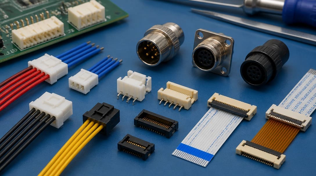
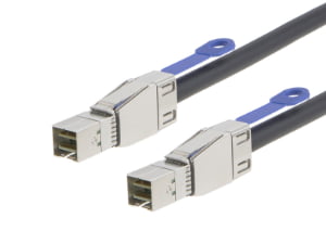
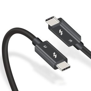
I/O connectors define how equipment speaks to the outside world. USB, RJ45, HDMI, D-Sub, M12, and M8 are the common faces. Every choice here locks in cable length limits, data rate, and the mechanical robustness of the connection. For a deep dive into the USB‑C standard, see our USB-C connector FAQ.
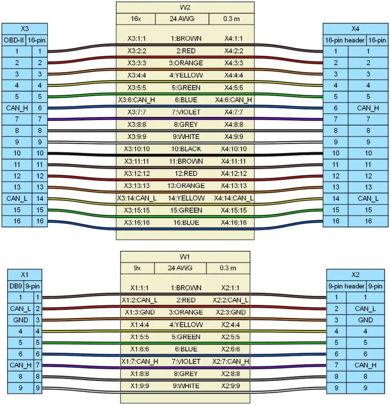
Circular connectors such as M12, M8, MIL-DTL types, and push-pull designs are chosen when ruggedness and environmental sealing matter more than density. Their metal or ruggedized thermoplastic shells protect against moisture, dust, and vibration. These connectors are frequently used in CAN bus systems in automotive and industrial automation.
FFC/FPC connectors address tight spaces, hinges, and sliding mechanisms in portable equipment. Flat flexible cables press directly into low-profile ZIF (zero insertion force) connectors. These demand careful material selection because a wrong actuator design can cut flex trace life in half.
Beyond the Photo: Four Parameters That Dictate Field Performance
A photograph shows only the shell. Real-world reliability comes from four details that most sample photos hide completely.
Termination method. Crimp, IDC (insulation displacement, such as insulation piercing connectors), solder cup, and press-fit all demand different tooling and process controls. A crimped contact needs a defined crimp height, verified with a pull tester, while IDC relies on proper wire gauge and insulation thickness.
Contact plating. Gold over nickel is standard for low-level signals and high mating cycles because it resists fretting corrosion. Flash gold (a few microinches) protects storage but wears through quickly. A 15µ” gold plate handles hundreds of cycles; 30µ” can last thousands. Tin plating costs less and works for high-current power contacts, but only if the application does not require frequent disconnection. Plating thickness matters—a connector that passes a continuity check on day one may fail in six months if the gold flash is too thin for its mating environment.
Current rating and temperature rise. The number printed on a datasheet assumes specific conditions. When all contacts in a connector carry current simultaneously, the rating degrades. Custom cable assembly designs that pack multiple power circuits in one housing must use derating curves published by manufacturers such as Molex and TE Connectivity. A connector rated for 9 A per circuit may only handle 6 A when all positions are loaded and ambient temperature reaches 60°C. Ignoring derating leads to softened housings, increased contact resistance, and eventual thermal runaway.
Environmental sealing. An IP rating isn’t a visual feature. Unsealed connectors fail quickly in humid or dusty environments, even indoors. IEC 60529 defines IP67 as protection against dust ingress and temporary immersion, while IP20 offers no liquid protection. If a connector will see washdowns, condensation, or outdoor exposure, the specification must state sealed or unsealed explicitly—not just a part number that “looks like” a waterproof unit.
| Parameter | Common Oversight | Production Impact |
|---|---|---|
| Termination method | Assuming “field installable” equals no special tooling | Intermittent circuits, rework hours |
| Contact plating | Choosing flash gold for high-cycle applications | Premature corrosion, signal dropouts |
| Current derating | Using single-contact rating for fully loaded housing | Overheated connectors, housing deformation |
| Environmental sealing | Basing IP rating on appearance | Moisture ingress, latent field failures |
Connector Family Showdown: Molex, TE, JST, and Others in Real-World Use
Once the functional category is clear, engineers typically narrow the field to a few widely supported connector families. Each has a distinct footprint, tooling ecosystem, and performance envelope.
The Molex Mini-Fit series, built on a 4.2 mm pitch, is ubiquitous in PC power supplies and industrial control. It handles around 9 A per circuit when properly derated. TE Connectivity’s AMPMODU line, with its 2.54 mm pitch, supports wire-to-board and board-to-board configurations and benefits from an immense supplier network that keeps tooling accessible.
JST’s XH (2.5 mm) and PH (2.0 mm) series appear in battery packs, small appliances, and low-cost control boards worldwide. Their primary sourcing trap is crimp tool compatibility—generic tools often produce inconsistent crimp heights on JST terminals, leading to terminal back-out or high contact resistance. Moving into harsh environments, Amphenol’s MIL-DTL circular connectors and Hirose’s high-density FPC solutions show how contact density, temperature range, and vibration resistance drive OEM selection. A Japanese wire harness manufacturing line delivering sensor assemblies for construction equipment may rely on Hirose circular connectors that maintain IP67 integrity after 2,000 mating cycles, while a laboratory instrument might use a far less rugged Amphenol option with gold-plated contacts rated for lower insertion forces.
The critical insight is that a 2.54 mm pitch, 10-pin housing from two different manufacturers can have measurably different contact resistance values when tested per EIA-364-06. One may be suitable for a door harness experiencing vibration and thermal shock; the other may be fine for a static indoor controller. The photo shows identical geometry; the material and plating stack tell the real story.
Quick Reference: Common Connector Family Matrix
To streamline your selection process, here is a comparison of widely used connector families in custom assemblies:
| Brand & Series | Pitch (mm) | Max Current (A)* | Typ. Wire Gauge | Common Application |
|---|---|---|---|---|
| Molex Mini-Fit Jr. | 4.20 | Up to 9.0A | 16-28 AWG | Power distribution, Industrial |
| Molex Micro-Fit 3.0 | 3.00 | Up to 8.5A | 20-30 AWG | High-density signal & power |
| TE AMPMODU | 2.54 | Up to 3.0A | 20-32 AWG | Logic boards, Instrumentation |
| JST XH Series | 2.50 | Up to 3.0A | 22-30 AWG | Battery packs, Appliances |
| Amphenol M12 (A-Coded) | Circular | Up to 4.0A | 18-24 AWG | Sensors, Factory Automation (IP67) |
(Note: Maximum current is heavily dependent on the number of loaded circuits and ambient temperature derating curves.)
Mating Isn’t Enough: Why ‘Compatible’ Requires Process and Specification Alignment
The word “compatible” on a datasheet often means the plug mechanically fits the receptacle. That is not the same as being fit for long-term operation.
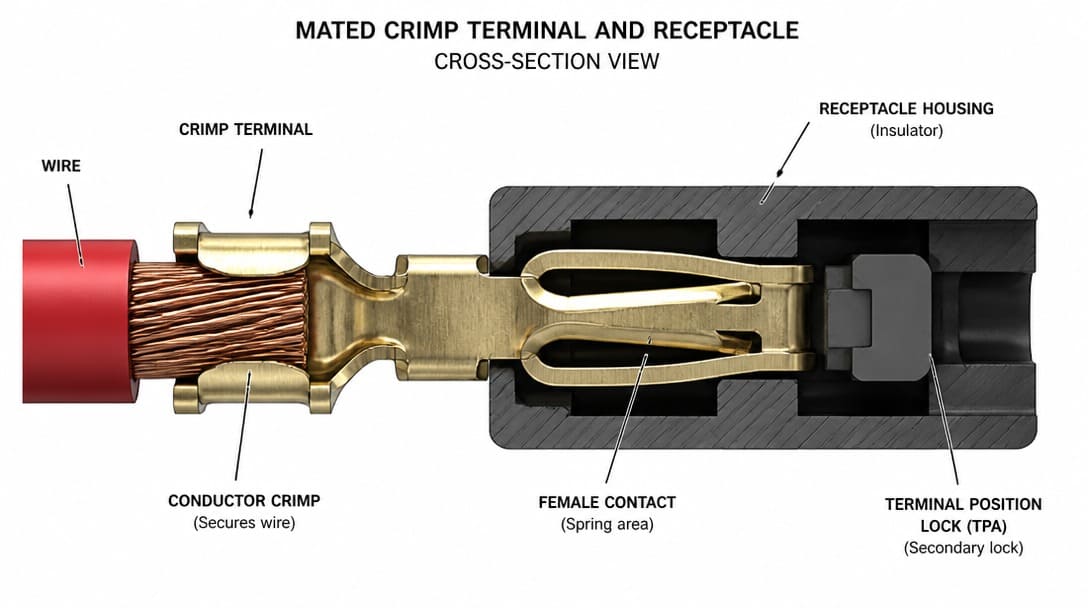
Physical mating between different series—or utilizing generic equivalent parts without validation—can lead to catastrophic field failures. The true test of compatibility lies in the crimp process. If a terminal requires a specific insulation diameter (OD), but the cable insulation is too thick or too thin, the strain relief crimp will fail. Furthermore, using generic hand tools instead of manufacturer-validated applicators creates inconsistent crimp heights. This results in terminal back-out, high resistance, and thermal failure under load.
To mitigate these risks, professional manufacturers mandate that all custom cable assemblies comply with IPC/WHMA-A-620 Class 2 or Class 3 standards. This standard strictly defines acceptable parameters for crimp height, bellmouth dimensions, and conductor brush length—ensuring that what looks compatible on a PDF actually performs reliably in the field.
Connector Selection Checklist: From Inquiry to First Article
Use this checklist to move from a vague inquiry to a specification that can be confidently released to production.
- Define the application environment. Indoor or outdoor? Vibration profile? Expected mating cycles? Ambient temperature extremes? These answers dictate sealing, plating, and retention requirements.
- Confirm termination method matches your production line. Crimp, IDC, solder, or press-fit—each demands specific tooling and operator training. If your floor is set up for crimping, do not introduce solder cups without planning the process change.
- Verify PCB footprint or wire gauge compatibility. Cross-check the connector drawing against your board layout and harness drawing. Confirm terminal wire range accepts your conductors exactly as specified (AWG or mm²).
- Check the plating specification. Gold flash, hard gold, or tin? The required durability and corrosion resistance must match the intended operating life. For RoHS compliance, all materials including the plating and housing must meet applicable substance restrictions.
- Obtain a physical sample and test. Don’t rely on a photograph or a PDF. Fit the sample into a test fixture that mimics the real assembly. Measure retention force and electrical continuity under representative mechanical loading before placing the bulk order.
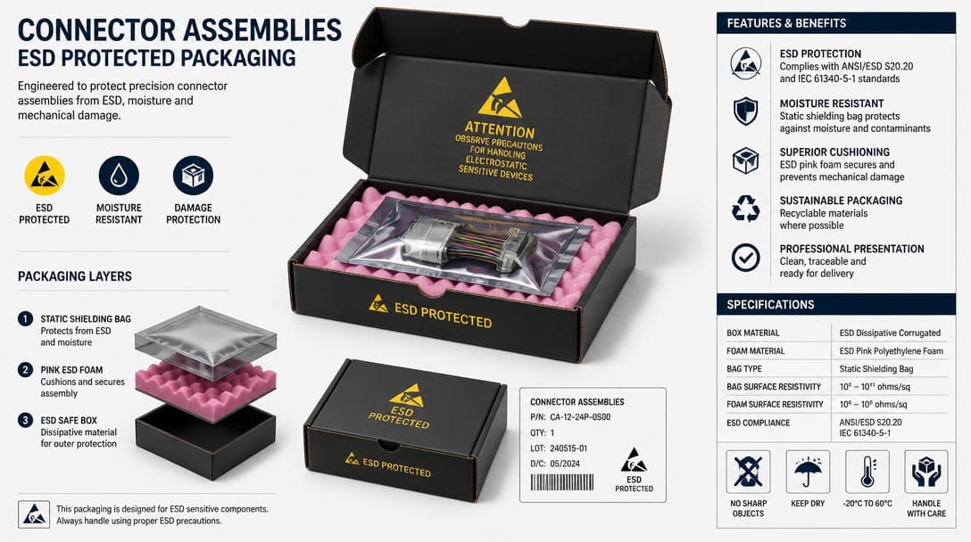
- Plan for quality inspection and export packaging early. Connectors and cable assemblies must survive international transit. Proper packaging prevents terminal deformation and ensures incoming quality checks can be performed efficiently.
For a structured starting point, download the free wire harness specification checklist to capture the critical parameters every connector inquiry should include.
When a Photo Match Isn’t a Production Match: EDOM’s Floor-Level View
“We regularly see connectors that look identical on a screen but behave completely differently on the production floor—the crimp barrel is sized for a metric wire gauge while your workshop uses AWG, or the solder tail length doesn’t clear your board’s thermal mass. The part looks right; the tooling and process know it’s wrong.”
A real example: a buyer purchases a housing that appears identical to a JST XH series. At first-article assembly, terminal retention lances crack because the housing material does not match the original specification’s glass-filled nylon. The parts passed visual inspection in the warehouse; the failure appears only when the operator inserts the terminal. Without a pre-production sample review, surface finish variations and contact geometry differences cause latent failures that escape final continuity checks but degrade in the field after a few hundred thermal cycles.
Suppliers such as EDOM Electronics address this gap through systematic requirement review—asking the clarifying questions about wire gauge, termination type, operating environment, and expected mating cycles that turn a one-line RFQ into a manufacturable bill of materials. Their process ensures that what gets approved at the sample stage is exactly what gets duplicated in production.
From Checklist to Quotation: How EDOM Bridges the Spec-to-Production Gap
A complete connector specification is only half the equation. Turning it into a reliable production part requires engineering liaison, sample coordination, and logistics planning.
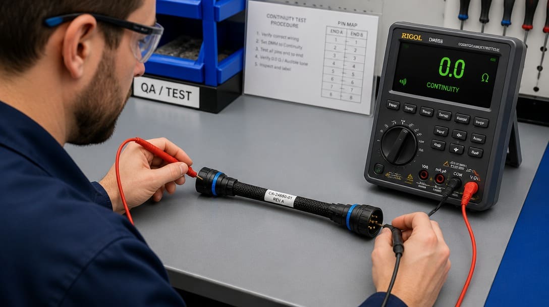
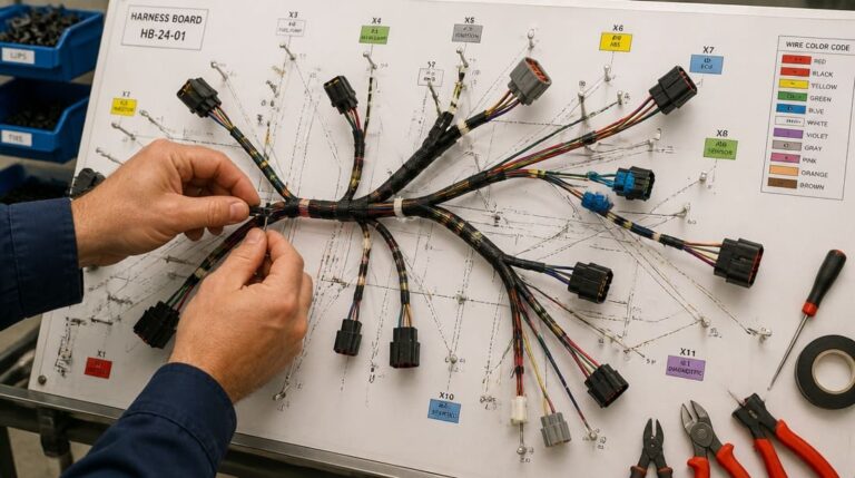
EDOM’s engineering review picks up where a typical e-commerce order stops. When a buyer sends a drawing, sample, or even a photograph, the technical team walks through the termination method, wire gauge, plating class, and environmental requirements point by point. The goal is a bill of materials that an OEM can trust to produce consistent results, whether the order is for 500 assemblies or a full container load of wire harnesses.
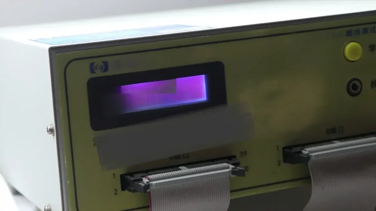
First-article samples undergo continuity, appearance, and fit testing before they leave the factory. Buyers see what they will actually receive—not a stock photo—and can check mating, retention, and pinout against their own jigs. Only after sample approval is the order released to production.
Export-ready packaging ensures connectors and assemblies arrive without bent pins, crushed housings, or moisture damage. This step is too often overlooked until a shipment shows up with damage that halts an OEM line.
Frequently Asked Questions
How do I know if I need a wire-to-board or a wire-to-wire connector?
If one end attaches to a PCB and the other end goes to a discrete wire, you need a wire-to-board connector. If both ends connect to cables—creating an in-line splice or junction—you need a wire-to-wire type. The distinction determines housing style, mounting features, and strain relief design.
Can I use the same connector family for prototyping and mass production?
Often yes, but only if the production termination method matches your prototyping process. If you hand-soldered a connector for a prototype, but the production plan calls for automated crimping, you must change the termination style and possibly the connector series. Confirm the production tooling path before finalizing the prototype BOM.
What is the most common oversight when matching connectors to a cable assembly?
The terminal wire range not matching the actual cable conductor size. A terminal may be specified for 0.3–0.5 mm² wire; if the design uses AWG 20 (about 0.52 mm²), the crimp quality will be marginal. Always cross-check the connector’s wire range with the exact conductor cross-section, including insulation thickness.
Does RoHS compliance affect connector selection?
Yes. Beyond the original restrictions on lead and cadmium, RoHS 3 (Directive 2015/863) restricts four specific phthalates (plasticizers) often found in older connector housings and PVC cable jackets. Additionally, strict compliance requires monitoring the REACH SVHC (Substances of Very High Concern) list. Always request updated material declarations from your supplier, rather than relying on legacy datasheets.
Can I use equivalent (cross-reference) connectors instead of original brands to reduce costs?
Yes, using high-quality equivalents can significantly reduce costs and lead times. However, this carries risks if not managed correctly. You must work with an assembly partner who can provide detailed cross-reference validation, including dimensional checks, material comparisons (UL 94V-0 flammability), and IPC-A-620 pull-force testing, to ensure the equivalent part performs exactly like the original in your specific environment.
Next Steps: From Universal ‘What Connectors?’ to Your Specific Assembly
The journey from a search for “what connectors” to a production-ready specification passes through functional categorization, hidden parameters like plating and derating, true compatibility verification, and a disciplined selection checklist. Photographs start the search; engineering details finish it.
For buyers managing international electronic connector sourcing, a partner that bridges the spec-to-production gap through drawing review, sample coordination, and export packaging can eliminate hours of internal rework. Learn more about EDOM’s connector solutions and custom assembly support to move your next project from a rough inquiry to a field-proven assembly.
-300x300.jpg)