If your cable assembly inspection ends when the continuity tester shows green, you’re catching open circuits and short circuits — but not the two failure modes that cause most field returns.
Direct Answer
A cable tester is any instrument that verifies electrical connectivity and isolation in a cable or wire harness assembly. (For a broader overview of the equipment family and incoming inspection workflows, see our comprehensive guide on What Is a Cable Tester: Function and Quality Inspection Uses).Beyond simple beep-and-light continuity, professional cable testing includes three core assessments: continuity (opens/shorts), pull force (crimp integrity), and hi-pot (dielectric withstand/insulation quality). Only a combination of these tests provides complete acceptance confidence for OEM and export cable assemblies.
What a Cable Tester Actually Does
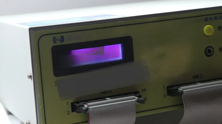
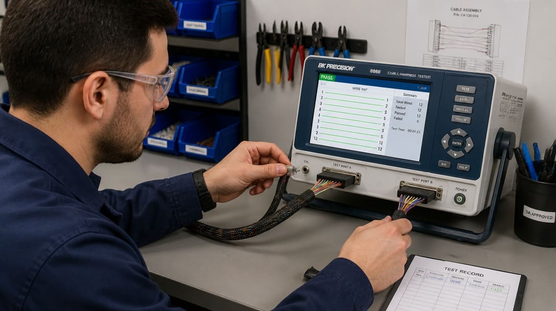
A cable tester validates the electrical path and insulation integrity of an assembled harness or cable. The simplest testers check continuity — lighting a green LED or sounding a beep when pin-to-pin resistance is low. But what an industrial-grade cable tester does goes much further. It can sequence through hundreds of test points, measure insertion resistance, apply high voltage to confirm dielectric withstand, and in many production environments, it is paired with pull-force measurement tools to verify the mechanical soundness of every crimped terminal.
The three fundamental tests — continuity, pull force, and hi-pot — each target a distinct failure mode that, if left undetected, can lead to intermittent field failures or safety incidents. OEM procurement teams and quality engineers need to know what each test catches and, critically, what it misses.
Why Continuity Testing Alone Isn’t Enough
Continuity testing verifies that a dedicated circuit path exists from pin to pin, capturing catastrophic open circuits, wire swaps, and direct short circuits. However, standard continuity testers employ a basic 2-wire method, which cannot isolate the minute contact resistance (milliohms) of a crimped joint from the internal resistance of the test adapter and fixtures. For high-current power cables or precision signal lines, experienced suppliers deploy 4-Wire Kelvin Measurement (low-resistance testing). By separating the current excitation and voltage sensing paths [1.1.2], this method bypasses fixture resistance entirely, allowing the tester to verify the true mechanical and electrical integrity of each crimp down to the mΩ level.
The limitation is what continuity cannot reveal. A crimp that makes electrical contact under no load can pass a low-current continuity check, yet the connection may be mechanically weak — strands loosely compressed inside the terminal barrel, a partly deformed crimp wing, or a wrong terminal size that holds only briefly. Under vibration, thermal cycling, or mechanical handling during installation, such a crimp can become intermittent or fail completely. These are exactly the failures that generate field returns after the assembly has left the production floor.
Equally invisible are insulation faults. A conductor nicked during stripping, a conduit worn thin during wire routing, or a RoHS[1]-compatible insulation that developed micro-cracks during handling — none of these affect continuity in a dry, static lab. But the moment voltage rises or humidity penetrates, the weakened insulation can break down, causing arcing or shorting between conductors. Continuity cannot warn of this. IPC/WHMA-A-620, the acceptance standard for cable and wire harness assemblies, defines strict criteria for crimp quality and insulation integrity precisely because these are known field risk points.
Test Coverage Table: What Each Test Catches and Misses
| Test Method | Detects | Misses |
|---|---|---|
| Continuity | Open circuits, short circuits between pins, basic wiring errors | Crimp mechanical strength, insulation breakdown, partial contact due to corrosion or deformation |
| Pull Force | Crimp retention force, terminal deformation, insufficient strand compression | Opens, shorts, insulation dielectric faults, conductor-to-conductor clearance issues |
| Hi-Pot (Dielectric Withstand) | Insulation breakdown, conductor-to-conductor clearance faults, pinhole arcs, moisture ingress paths | Opens, crimp quality (mechanical), intermittent low-voltage contacts |
Only a combined test protocol of continuity, pull force, and hi-pot builds a complete quality picture. Relying on any one method leaves a gap that can lead to undetected defects and eventual field returns.
Request a quality inspection checklist for cable assemblies — a practical tool that maps each test to the relevant acceptance standard.
Pull Force Testing: The Crimp Integrity You Can’t See
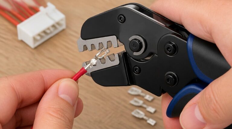
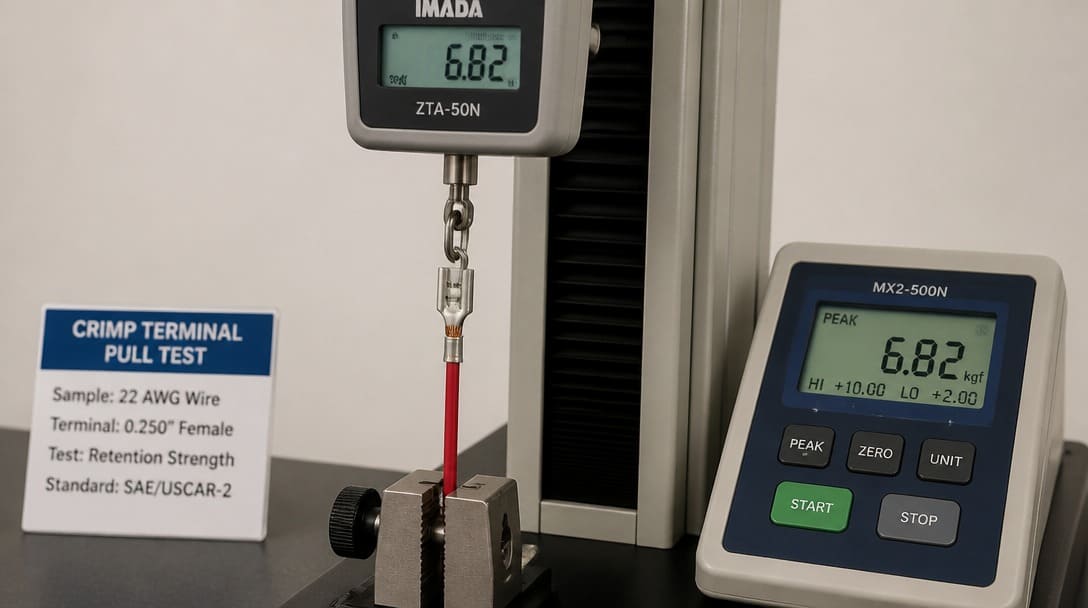
A crimp that passes a continuity check can still fail mechanically. If the terminal barrel does not compress the conductor strands evenly, an air gap may exist that a continuity tester sees as a closed circuit because the components touch under zero load. In the field, vibration or thermal expansion turns that marginal connection into a flickering or open circuit.
Pull force testing directly addresses this gap. A calibrated pull tester grips the conductor and applies a steadily increasing axial load until the conductor separates from the terminal. IPC/WHMA-A-620 specifies minimum pull force values for different wire gauges and terminal types. For example, a 20 AWG wire in a standard crimp terminal requires a pull force exceeding specific thresholds depending on the quality class — Class 1 (general electronic products), Class 2 (dedicated service), or Class 3 (high performance). A crimp that separates below the threshold fails, even if it showed perfect continuity.
Common failure modes caught only by pull force testing include incomplete compression of the crimp barrel, use of an incorrect terminal size for the conductor cross-section, oxidation that prevents proper cold welding, and insufficient strand count within the terminal due to wire damage before crimping. IPC J-STD-001, which covers soldered and crimped connections acceptance for printed board assemblies, similarly requires visual and pull-force verification for crimped contacts. In wire harness manufacturing environments, suppliers integrate pull force sampling at the start of a production run and at regular intervals to validate crimp tooling setup.
For OEM buyers sourcing custom cable assemblies or wire harnesses, pull force evidence should be a standard part of the production documentation — exactly the kind of data that separates a compliant shipment from a latent field risk.
Hi-Pot Testing: Exposing Invisible Insulation Breakdown
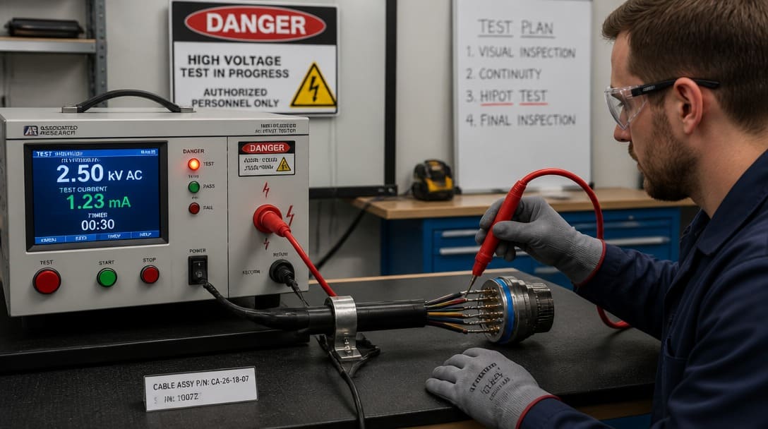
Insulation defects do not reveal themselves during continuity testing or even visual inspection. A conductor with a hairline nick from an improperly set stripping blade, or an insulation tube with a thin spot from routing through a tight loom, will pass low-voltage checks. But when the assembly carries its rated voltage — or experiences environmental stress — those weak points can become breakdown channels.
Hi-pot (high potential) testing applies a voltage higher than the assembly’s rated operating voltage between conductors, and between conductors and shield, for a defined duration. The test measures leakage current; if insulation breaks down or arcs over, the failure is immediate. IPC/WHMA-A-620 sets dielectric withstand voltage levels and pass/fail criteria, often referencing the assembly’s rated working voltage and applicable product safety standards such as UL requirements. UL-recognized components and tested insulation systems require hi-pot compliance to maintain listing integrity.
Failures caught by hi-pot include conductor-to-conductor flashover due to reduced clearance, pinholing in insulation from manufacturing damage, contamination (flux, moisture) that creates a conductive path, and stress cracks in RoHS-compatible insulation materials, which can be more brittle than their non-RoHS predecessors. RoHS transition brought new insulation compounds; without hi-pot validation, these materials may exhibit lower dielectric strength, a risk that is invisible until the assembly is fielded.
In practice, hi-pot is the test that confirms that the assembly is electrically safe. For custom cable assemblies destined for industrial equipment, medical devices, or export markets, skipping hi-pot is a liability OEM buyers cannot afford.
Why EDOM Makes Pull Force and Hi-Pot Standard on Every Outgoing Shipment
“We made pull force testing and hi-pot standard on every outgoing shipment — not because customers always ask for it, but because the failure modes that cause field returns are exactly the ones continuity testing cannot catch.”
This approach reflects a production coordination philosophy: field failures erode trust, delay downstream assembly lines, and cost far more than the incremental testing time. Inline at the manufacturing site, the process follows a quality management model consistent with ISO 9001 principles. Incoming materials — connectors, terminals, wire — are inspected before production. Crimping tools are validated through pull force sampling. Each completed assembly then undergoes hi-pot testing, followed by a final continuity and visual check. This structured sequence ensures every export-ready unit satisfies the acceptance criteria of IPC/WHMA-A-620 Class 2 or Class 3.
For OEM customers, having pull force and hi-pot built into the standard workflow means receiving assemblies with documented electrical and mechanical integrity, ready for installation without hidden risk. It transforms testing from an afterthought into a predictable, repeatable quality gate.
Troubleshooting: Why Did My Cable Assembly Fail Hi-Pot Testing? — 4 Common Causes
When a hi-pot test failure occurs, the root cause is not always obvious. A systematic troubleshooting approach isolates the fault and prevents recurrence.
- Conductor damage during stripping or crimping. Nicked insulation creates a weak point that arcs under high voltage. Check the strip length and blade condition. Even a shallow cut into the conductor insulation is a failure waiting to happen.
- Excessive solder wicking into the wire. For soldered terminals, solder can flow up the strands under the insulation, reducing clearance and creating a flashover path. IPC J-STD-001 defines acceptable solder wicking limits; exceeding them invites dielectric failure.
- Contamination. Moisture, flux residues, or conductive dust bridging between contacts can lower insulation resistance dramatically. Inspect the failed assembly under magnification for residue or moisture ingress.
- Design or material issue. Insufficient insulation thickness for the test voltage, incorrect voltage rating, or a RoHS-compatible insulation with lower dielectric strength. Verify the material specification against the hi-pot voltage requirement and assembly voltage rating.
A hi-pot failure is a quality signal, not merely a yield problem. Each failure traced to its root cause strengthens the manufacturing process and prevents the next one.
From Testing to Shipment: What Happens After Acceptance
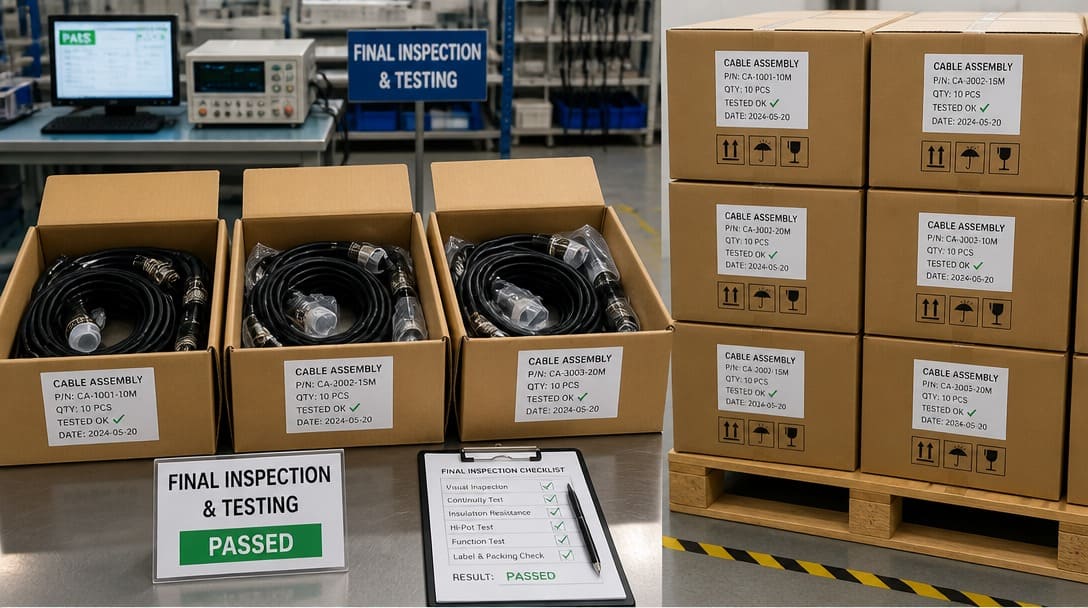
Passing continuity, pull force, and hi-pot tests marks the final verification of electrical and mechanical integrity, but it is one part of a broader pre-shipment protocol. Assemblies then undergo final routing, labeling, looming, and custom packaging tailored to the buyer’s requirements. For international OEM shipments, this means reinforced outer packaging, anti-static protection, moisture barriers, and proper carton labeling to survive transit and arrive without damage.
Testing and packaging are linked: a perfectly tested assembly can be scratched, crushed, or contaminated during poorly planned packing. That is why leading suppliers combine in-process quality gates with export-ready packaging procedures. Explore the full quality inspection and export packaging process to understand how these steps work together to protect connector pins, terminals, and cable jackets from door to installation.
For OEM buyers sourcing custom cable assemblies, verifying that the supplier treats failure-mode-specific testing and protective packaging as a single continuous process reduces arrival defects and streamlines incoming inspection.
Frequently Asked Questions
What is the difference between a continuity tester and a hi-pot tester?
A continuity tester checks that current flows through a conductor path at low voltage; it detects opens and shorts but cannot assess insulation quality. A hi-pot tester applies high voltage to verify that insulation can withstand rated operating conditions without breaking down. Continuity testing alone does not guarantee electrical safety or long-term reliability.
Does every cable assembly need pull force testing?
Not every assembly needs 100% pull force testing, but every production run should include pull force verification at setup and at intervals as defined by IPC/WHMA-A-620. For safety-critical or high-reliability applications, sampling documented pull force data is essential to prove crimp quality. For OEM buyers, requiring pull force records as part of the supplier’s in-process control is a best practice.
What hi-pot voltage should a cable assembly be tested at?
The test voltage depends on the assembly’s rated working voltage, application standard, and relevant safety requirements. IPC/WHMA-A-620 provides guidelines, typically testing at 2× rated voltage + 1000 V for many industrial assemblies, but exact values must follow the product specification and applicable UL or IEC standards. The assembly drawing or spec sheet should define the hi-pot parameter.
Can a cable pass continuity and fail hi-pot?
Yes, frequently. A nicked insulation, contaminated surface, or inadequate clearance can pass continuity because the low voltage does not stress the dielectric. Only the elevated voltage of a hi-pot test exposes the weakness. This is one of the most common reasons that relying solely on continuity creates field reliability gaps.
How is IPC/WHMA-A-620 related to cable testing?
IPC/WHMA-A-620 is the acceptance standard for cable and wire harness assemblies. It defines the criteria for crimp pull force, insulation placement, soldering quality, and dielectric withstand voltage testing. Suppliers and OEM buyers use this standard to establish pass/fail limits, ensuring that tested assemblies meet consistent, industry-recognized quality levels.
Key Takeaways
- A cable tester’s true value is revealed only when it combines continuity, pull force, and hi-pot assessments — each catches failure modes the other two miss.
- Continuity testing alone leaves crimp integrity and insulation quality unverified, the very defects behind most intermittent field failures and safety incidents.
- Pull force testing confirms mechanical reliability of crimps according to IPC/WHMA-A-620, while hi-pot testing exposes invisible insulation breakdown before the assembly reaches the field.
- Standardizing pull force and hi-pot in outgoing inspections, as done by production-savvy suppliers, directly reduces field returns and protects OEM production uptime.
- Completed assemblies require export-grade packaging to preserve test results during transit; testing and packaging are a single quality chain from factory to installation.