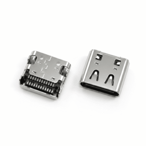
If you are sourcing a USB-C connector from a part number on a drawing and you think matching the 24-pin count and the physical cutout dimensions is enough — this article covers the four parameters invisible from a photo that determine whether your production line will assemble it without rework.
At a Glance
Direct Answer A USB-C connector is a reversible, high-speed interface governed by the USB-IF specification. While the standard dictates the external mating profile, the internal design—including pin count (24-pin, 16-pin, or 6-pin), plating thickness, shell grounding, and SMT thermal mass—varies by manufacturer. For OEM buyers, a USB-C connector is a highly process-sensitive component requiring rigorous Design for Manufacturing (DFM) verification before SMT assembly.
A USB-C connector is not a single interchangeable part. It is a 24-pin reversible interface defined by the USB-IF standard, but the physical receptacle or plug you purchase is a proprietary component design from manufacturers such as Molex, TE Connectivity, JST, Amphenol, or Hirose. Two USB-C connectors that share the same mating face may differ radically in soldering process requirements, board retention mechanics, plating specifications, and grounding schemes. For OEM buyers, swapping one brand for another without evaluating these invisible parameters can derail SMT production, compromise field reliability, and invalidate regulatory approvals.
What Exactly Is a USB-C Connector? (It’s Not One Part)
While a standard connector joins two circuits (for a comprehensive breakdown of connector mechanics, see our OEM Guide on What a Connector Is), the term “USB-C” specifically describes a stringent interface specification defined by the USB-IF — not a universal, off-the-shelf component.The USB Implementers Forum (USB-IF) publishes the mechanical, electrical, and protocol requirements that define the 24-pin reversible connector outline, signal assignments, and performance characteristics. Every manufacturer that builds a USB-C receptacle or plug designs its own internal terminal geometry, shell grounding approach, solder anchor structure, and plating stack to meet that specification.
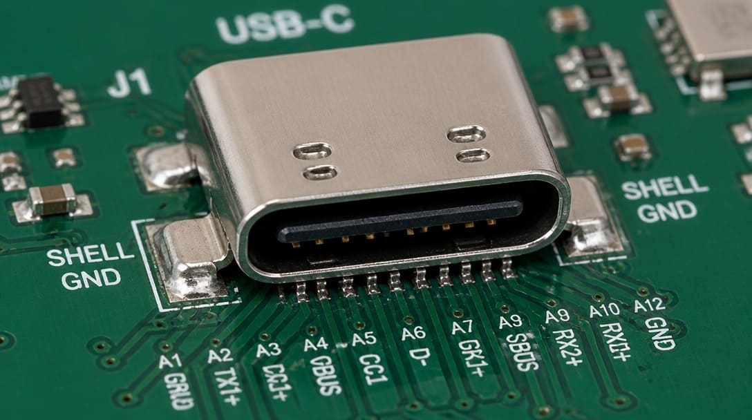
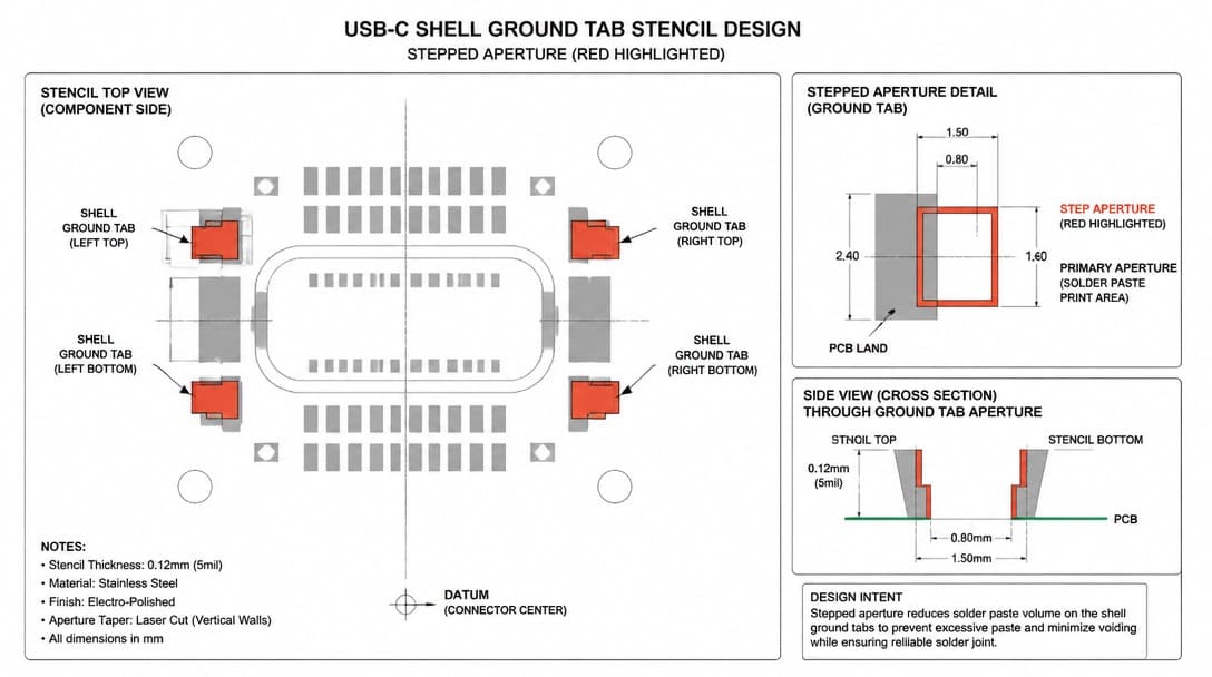
This means two USB-C receptacles from different sources — a Molex part and an Amphenol alternative, for example — will fit the same USB-C plug, route the same signals, and appear identical in a top-down photograph. Yet one may require a stepped stencil for the shell ground tabs during assembly, while the other works with a flat stencil. One may survive 10,000 mating cycles thanks to 30 micro-inch gold plating; the other may show contact resistance drift after a few hundred cycles with only a gold flash. The part number on your BOM guarantees the interface, not the manufacturing process window or the long-term durability.
The Illusion of Interchangeability: Why a Photo and Pin Count Aren’t Enough
Engineers and procurement managers often perform a visual comparison between the drawing they hold and a datasheet from a new source. They confirm the 24 pins, the cutout dimensions, and perhaps the mounting style — and then issue an RFQ. This approach works for fasteners or passive mechanical parts, but it falls short for a connector that sits at the intersection of SMT process control, mechanical stress, and high-speed signal integrity.
What’s missing from the photograph:
- Thermal mass distribution. Shell thickness, ground tab size, and internal copper alloy mass all influence how the connector absorbs heat during reflow. A connector that draws heat differently can cold-solder fine-pitch signal pins while properly reflowing the shell tabs — or vice versa.
- Stencil aperture requirements. Some USB-C receptacles need a stepped stencil or custom aperture geometry for the shell ground pads to achieve adequate solder volume without bridging the adjacent signal pins.
- Plating thickness and underplate composition. “Gold plating” can mean 3 micro-inches or 30 micro-inches, nickel or palladium-nickel underplate, phosphor bronze or brass base metal. Each combination produces a different life cycle and corrosion resistance.
- Mechanical anchoring against wrenching torque. Through-hole (THT) retention pins act as structural anchors to resist brutal cable-side torque and bending moments; pure SMT versions rely solely on the solder pad’s peel strength. This choice critically affects mechanical shock resistance (per EIA-364-27) and system-level drop test survivability, even if the connector easily passes a static benchtop fit-check.
A connector that mates perfectly in a prototype can cause tombstoning, opens, or early field returns in volume production if these invisible factors don’t align with the validated process. That initial fit-check creates a false sense of security that many production teams discover only after several hours of line stoppage.
Hidden Parameter: Pin Count (Do You Really Need All 24 Pins?)
The USB-IF specification defines a 24-pin layout for full-feature (data, video, and up to 240W power) applications. However, blindly specifying a 24-pin receptacle for a device that only requires battery charging is a costly engineering mistake.
To optimize BOM cost and reduce SMT defect rates (by avoiding ultra-fine 0.25mm pitch soldering), OEM buyers must match the pin count to the actual device function:
| USB-C Connector Type | Pin Count | Supported Functions | Ideal OEM Applications |
|---|---|---|---|
| Full-Feature | 24-Pin | USB 3.2/4.0, DisplayPort, PD | Laptops, Docking Stations, High-speed cameras |
| Data & Power | 16-Pin | USB 2.0 (480 Mbps), Power | Smartphones, IoT Gateways, Smart Home Hubs |
| Charge-Only | 6-Pin | Power Delivery (PD) only | Bluetooth speakers, E-cigarettes, Basic wearables |
(For a broader understanding of how connector specifications align with overall system requirements, refer to our foundational OEM Guide on What a Connector Is.)
Hidden Parameter #1: Soldering Process Compatibility
USB-C receptacles vary widely in the thermal profile they require during SMT assembly. A connector with a thick stainless steel shell and large ground tabs acts as a heat sink, demanding a longer soak time or higher peak temperature than a connector with a thinner shell and smaller tabs. If an assembly line has been tuned for one specific USB-C part number, the reflow oven profile, stencil thickness, and solder paste type have all been dialed in for that component’s thermal characteristics.
Case Study from the Assembly Line: In a recent production run for a smart-home hub OEM, the CM swapped an approved 24-pin USB-C receptacle for a visually identical, lower-cost alternative. Because the new connector possessed a 30% larger thermal mass in its shell grounding tabs, the existing reflow profile failed to activate the solder paste fully. This specific mismatch resulted in a 12% tombstoning defect rate on the signal pins. The result was hours of troubleshooting— not because the new part was defective, but because its thermal mass and solder-joint geometry were different enough to fall outside the existing process window. The result was hours of troubleshooting, stencil rework, and profile adjustment before acceptable yields returned. This hidden cost of requalification can easily outweigh any unit-price savings from an alternative source.
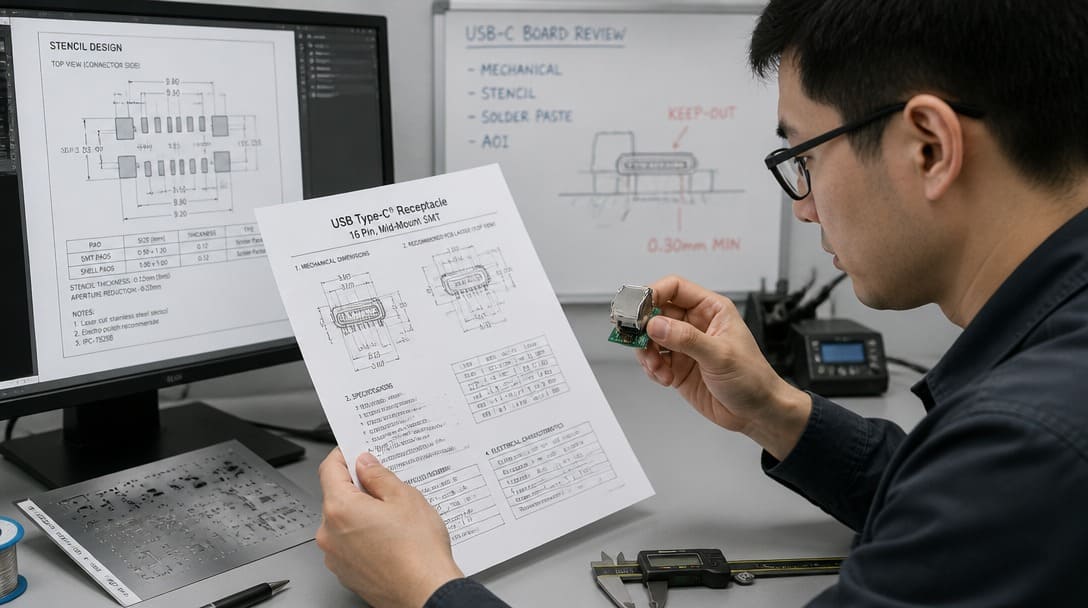
Before qualifying a new USB-C source, obtain the manufacturer’s recommended stencil aperture design and reflow soldering profile from the official datasheet. Compare these to your current process window. Even small differences can demand a modified stencil, a different solder paste alloy, or a re-tuned oven — all of which add time and risk.
Avoid SMT Disasters with Your USB-C BOM
Don’t risk your production yield on visually identical but thermally mismatched connectors. Send us your PCB footprint and target component drawing. Our DFM engineers offer a Free Cross-Reference & Process Compatibility Audit to ensure your alternative source is truly drop-in replaceable.
Hidden Parameter #2: Plating Specifications — More Than Just “Gold”
Many drawings and BOMs list the plating as simply “Au” or “Gold.” That one-word description conceals a multi-layer stack that determines how long the connector will maintain a stable low-resistance contact. A gold flash of a few micro-inches may suffice for infrequently mated internal connections, but a USB-C port that faces daily plugging and unplugging needs a more robust plating layer.
The difference between 3 micro-inches of gold and 30 micro-inches over nickel can mean hundreds of mating cycles versus thousands. Underplate materials matter too: a nickel underlayer thickness of 50–100 micro-inches (1.27–2.54 µm) is common, but variations can affect corrosion resistance. Base materials — phosphor bronze versus brass — influence spring force retention and fatigue life. A connector may pass initial continuity verification but exhibit rising contact resistance after environmental aging if the plating stack was not designed for the intended application severity.
Industry test standards such as EIA-364 (specifically EIA-364-23 for contact resistance and EIA-364-09 for durability) provide a framework for verifying that a connector’s plating and mechanical performance match the application. When evaluating a substitute, request qualification test data that demonstrates equivalent performance, not just a material declaration. Additionally, confirm that RoHS compliance covers the entire plating stack — including nickel barriers and surface finish — not merely the outer gold layer. A restricted substance in the underplate can block exports to regulated markets.
| Plating Specification | Typical Durability (Mating Cycles) | Application Note |
|---|---|---|
| Gold flash (3–5 micro-inch) | Hundreds | Internal, low-cycle connections |
| 10–15 micro-inch gold | 1,000–5,000 | Consumer electronics, moderate use |
| 30 micro-inch gold | 10,000+ | High-cycle, industrial, medical |
| 50 micro-inch gold | 20,000+ | Mission-critical, harsh environment |

Hidden Parameter #3: Board Retention Mechanism — Through-Hole vs. Pure SMT
Two USB-C receptacles can look identical from the top but behave completely differently when a user yanks a cable sideways. Pure SMT versions rely on solder joints between the shell tabs or pads and the PCB for mechanical anchoring. Through-hole designs add metal pins that penetrate the board, often soldered via wave or selective soldering after SMT reflow. The difference is invisible in a top-view photo but decisive under mechanical stress.
If an end product will experience frequent plug cycles, cable torque, or potential drops, a pure SMT connector risks pad lifting or solder joint fracture. mechanical shock resistance per EIA-364-27 commonly expose these weaknesses, even if the connector passed functional testing on the bench. A design that passes electrical verification may still fail mechanical qualification when the retention mechanism is mismatched to the product’s physical usage profile.
Through-hole anchors offer dramatically higher retention force and are the safer choice for handheld devices, instrumentation panels, and equipment subject to vibration. However, they alter PCB layout — the board must have plated through-holes — and often add a secondary soldering step that increases assembly complexity and cost. A buyer who selects a USB-C source simply by matching the digit on the BOM may end up with the wrong retention type, delaying the product launch until the board design or the connector source is changed.
Hidden Parameter #4: Shell Grounding Path — EMI and ESD Implications
The metal shell of a USB-C connector is not just a mechanical alignment guide; it forms the primary path for electromagnetic interference (EMI) shielding and electrostatic discharge (ESD) return. How that shell connects to the PCB ground plane affects high-speed signal integrity and the product’s ability to pass regulatory emissions testing (FCC, CE).
Some USB-C receptacles use a single contact point, while others deploy multiple spring fingers or full-length solder tabs that create a continuous ground path around the connector perimeter. In applications using USB 3.1, USB 3.2, or USB4 data rates (5 Gbps and above), a poor grounding scheme can cause impedance discontinuities, increased radiated emissions, or ESD failures during compliance testing. A substitution that changes the shell grounding design — even if the connector mechanically fits and communicates fine at low speed — may push the system outside the required EMI margin.
When evaluating an alternative USB-C source, confirm the grounding mechanism and match it to your design’s signal speed and ESD requirements. A high-speed design that passed testing with a multi-point ground shell may fail with a single-point ground version, and that failure often appears only at the compliance lab, far downstream in the development cycle.
Pre-Order Verification Checklist: 4 Steps OEM Buyers Should Take
- Confirm soldering process compatibility. Obtain the stencil aperture recommendations and reflow soldering profile directly from the connector manufacturer’s datasheet. Do not assume your existing profile will work for a new source.
- Verify plating specifications. Ask for plating thickness in micro-inches or microns for both mating contacts and solder tails. Request qualification test data per EIA-364 methods (durability, contact resistance, mixed flowing gas). Ensure RoHS compliance extends through the entire plating stack.
- Validate the board retention mechanism. Identify whether the receptacle uses through-hole anchors, pure SMT anchors, or a hybrid approach. Cross-reference with your product’s mechanical shock, drop-test, and insertion/removal force requirements.
- Check mating-cycle rating under real operating conditions. Confirm that the cycle rating was tested under conditions that reflect your product’s use: dust exposure, temperature extremes, vibration. If the end product requires UL listing, verify that the connector’s UL file number matches your component category and end-product requirements.
Need help reviewing these parameters for your USB-C connector source? EDOM’s engineering support can assist with connector matching, stencil review, sample confirmation, and production-coordinated supply. Contact EDOM or explore electronic connector solutions for OEM programs.
From Connector Match to Production-Ready Supply
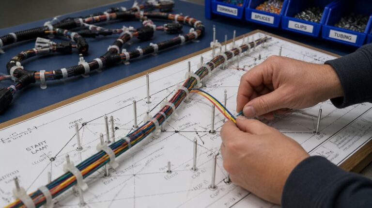
Even after the technical parameters are verified, OEM buyers need more than a single component sample. They need a partner that can manage consistent supply, protect connector plating and terminal alignment during export, and coordinate the entire flow from drawing review to shipment. For assemblies that embed the USB-C connector into a larger wiring system — such as a custom cable assembly or wire harness — the sourcing scope expands to include crimping, overmolding, continuity testing, and final inspection.
A production-coordinated approach closes the gap between a technically sound substitute and a stable, compliant supply. That includes quality inspection and export packaging that protects connectors from moisture, mechanical damage, and ESD during international transit. When the connector is sourced alongside cable assemblies or wire harnesses, the entire subassembly can be verified as a single coordinated offering — reducing the risk that a connector defect discovered at the harness level will cascade into final-product testing delays.
For OEM buyers navigating USB-C connector selection, the right sourcing partner understands that the part number is just the starting point. From connector cross-referencing and sample confirmation through to production follow-up and shipment preparation, the four invisible parameters must remain visible throughout the supply chain. Explore electronic connector and cable assembly solutions for your next OEM program — from a single drawing to stable, compliant supply.
Stop Guessing on Your USB-C Implementation
A visually identical USB-C replacement can crash your SMT yield if the thermal mass or stencil aperture isn’t matched. Don’t leave your production line to chance. Send EDOM Electronics your current PCB layout and component drawing. Our engineers will provide a Free USB-C DFM (Design for Manufacturing) Review to ensure reliable soldering, optimal pin-count selection, and secure secondary sourcing. Request Your Free DFM Review Today
Frequently Asked Questions
Can any USB-C connector be used as a replacement if the pin count and footprint match?
No. Pin count and footprint matching are necessary but not sufficient. Hidden parameters like soldering process compatibility, plating thickness, retention mechanism, and shell grounding path differ between manufacturers and can cause production defects, field failures, or regulatory non-compliance even when the physical outline is identical.
What is the most common mistake when sourcing an alternative USB-C connector?
Assuming that visual similarity or a successful bench fit-check guarantees production-line compatibility. The thermal mass difference alone can shift the reflow window enough to create tombstoning or insufficient solder joints, costing days of line requalification.
Which industry standards apply to USB-C connector qualification?
Manufacturers commonly reference EIA-364 test methods for contact resistance, durability, and mechanical shock. For end products, UL certification may be required, and the connector’s UL file number must align with the end-product listing. Additionally, RoHS compliance must cover the entire plating stack, not just the surface gold.
How do I confirm that a USB-C connector will survive my product’s expected plug cycles?
Request the mating-cycle test report from the supplier, and confirm it was conducted under conditions that reflect your operating environment — including temperature, humidity, and dust. Compare the reported plating thickness and base material to your requirements. A datasheet that lists only “Au” is insufficient; demand micro-inch or micron values for the entire plating stack.
Does the USB-C connector brand affect EMI and ESD performance?
Yes. The shell grounding design — single-point versus multi-point — directly affects shielding effectiveness and ESD return path impedance. Swapping brands can alter the system’s electromagnetic compliance margin, potentially causing radiated emission or ESD failures during FCC or CE testing.
Key Takeaways
- USB-C is an interface standard, not an interchangeable component; different brands implement the same mating face with unique internal designs, plating stacks, and retention methods.
- Four invisible parameters — soldering process compatibility, plating specifications, board retention mechanism, and shell grounding path — determine whether a connector will work in production and survive in the field.
- A fit-check on a benchtop does not guarantee process window compatibility or long-term reliability; hidden thermal mass, stencil aperture, and mechanical anchoring differences demand thorough evaluation.
- OEM buyers should verify datasheet-derived stencil and reflow profiles, plating thickness in micro-inches, retention type, and grounding scheme before qualifying a new USB-C source.
- Production-coordinated supply, including quality inspection and export packaging, ensures that the connector’s performance survives transit and integrates smoothly into higher-level assemblies such as custom cables or wire harnesses.