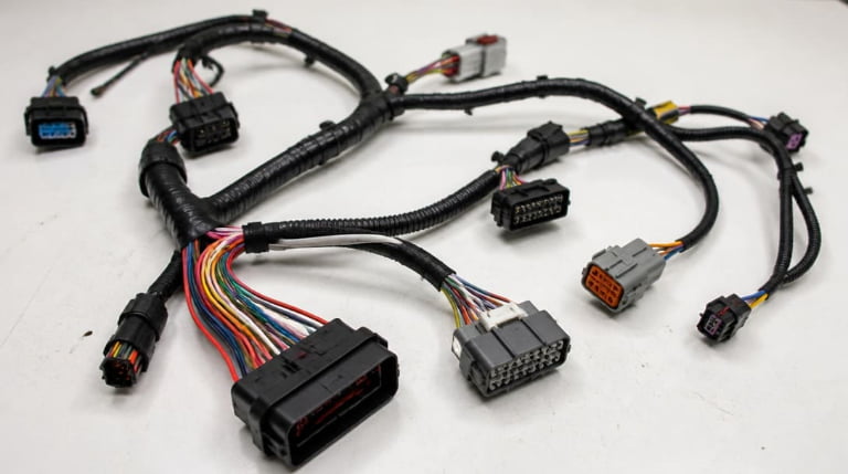
If you’re looking at an aerospace project specification or a drawing calling for an “aerospace cable harness” and you’re not sure what makes a harness genuinely aerospace-grade beyond high-temperature wire — this article covers the design constraints, material requirements, documentation, and process decisions that separate an airworthy harness from a commercial one, and the checks you need before placing an order.
Direct answer: An aerospace cable harness is governed by AS50881, the wiring design and installation standard for aerospace vehicles. Airworthiness depends on four layers beyond component selection: mechanical routing rules (bend radii, securement intervals), material compatibility validated for outgassing and thermal stress, full lot-traceable documentation with acceptance test data, and a crimp-and-shield process that meets SAE AS7928 and system-level EMI/EMC requirements. A harness assembled from MIL-spec parts but built without these four layers is not certifiable.
The Standard That Governs Aerospace Cable Harnesses
Many engineers assume that specifying MIL-DTL-16878 wire and MIL-DTL-38999 connectors produces an aerospace harness. That assumption collapses the first time an airworthiness reviewer asks for the routing standard followed during installation design.
AS50881 is the foundational document. It covers wiring design, harness fabrication, routing, clamping, and installation practices for aerospace vehicles — rotorcraft, fixed-wing, and uncrewed systems alike. It is not a component specification. It prescribes how wires must be bundled, how far apart clamps must be placed, what minimum bend radii apply at different bundle diameters, and how harnesses must be supported through pressure bulkheads and across flex zones.
Supplementary specifications fill in performance boundaries that AS50881 alone does not define. MIL-HDBK-522 provides wiring design guidelines that inform routing decisions early in the layout phase. MIL-STD-704 defines aircraft electrical power quality, shaping conductor sizing and voltage drop calculations that ripple into harness design. DO-160 governs environmental qualification — vibration, temperature altitude, humidity, and salt fog — meaning the harness must survive tests that expose poor routing and weak material choices within hours, not years.
A harness can pass a bench continuity test with every connector pinned correctly, every crimp visually acceptable, and still fail qualification because the bundle was secured every 18 inches instead of every 12 in a high-vibration zone. AS50881 does not care whether the parts are “aerospace-grade” on paper. It cares whether the assembly was designed and installed to its rules.
Design Rules Hidden Beyond the Drawing Dimensions
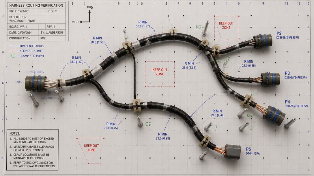
A 2D harness drawing captures lengths, connector orientations, and breakout locations. It rarely captures what determines survival in flight: how the bundle bends when the airframe flexes, how heat from adjacent equipment derates the conductor, and where a seemingly adequate clearance becomes a chafe point after installation.
AS50881 section 4 defines routing requirements that directly affect harness longevity. Minimum bend radii — typically a multiple of the bundle outer diameter — prevent conductor fatigue at turns. Securement intervals prevent the harness from oscillating under vibration and rubbing against structure, fasteners, or adjacent bundles. A harness that looks clean on a form board but exits a bulkhead connector at a sharp angle without strain relief will fail, not because the wire was wrong but because the routing violated the standard’s mechanical envelope.
Wire gauge de-rating is another design control that does not appear in most BOMs. A conductor sized for 10 amps at 25°C ambient may need to be de-rated to 7 amps or less when routed through a zone that reaches 85°C continuous. The current rating on the wire datasheet assumes standard conditions; the harness design must account for the thermal environment of the actual installation. Failing to do so leads to insulation breakdown that no connector selection can fix.
Harness shape-out — pre-forming the bundle in a mock bay or on a 3D fixture that replicates the installation path — catches interference points that 2D drawings miss. It validates that the harness can be routed without pulling on connectors, that breakouts align with equipment access points, and that sufficient slack exists where thermal expansion and contraction will pull on the bundle over thousands of cycles.
Material Choices That Silently Compromise Airworthiness
Here is the material trap that catches more programs than any single connector mating error: a bill of materials filled with legitimate aerospace part numbers, undermined by one or two industrial-grade substitutions that looked equivalent on a datasheet. As highlighted in our quality and compliance guide for aerospace wire harness manufacturers, these substitutions bypass qualification tests and introduce parts that have never been validated for outgassing, cold-flow resistance, or the specific plating stack that the airworthiness reviewer expects.
Outgassing. NASA and ESA maintain outgassing requirements that disqualify many industrial polymers. A silicone boot or a non-certified heat-shrinkable tubing may release volatile condensable materials under vacuum, contaminating optics, sensors, or conformal coatings in adjacent compartments. If the harness routes through an unpressurized or poorly ventilated bay, every polymer in the bundle — sleeving, boots, adhesive-lined tubing — must meet outgassing limits or be excluded from the design.
Silver-plated copper corrosion. Silver-plated conductors offer excellent conductivity and high-temperature performance, but they require deliberate corrosion prevention strategies. When a silver-plated wire mates with a connector contact that uses a different plating system — tin, for example — galvanic corrosion can initiate at the interface. Connector suppliers including Amphenol, TE Connectivity, and Molex offer multiple plating options across their product lines; the compatibility check between wire plating and contact plating must happen before the first crimp.
Dissimilar metals in connector shells. An aluminum connector shell mated to a stainless steel backshell without the appropriate protective finish creates a galvanic couple. Thermal cycling and moisture exposure accelerate thread seizure and structural degradation. The material callout on the drawing must specify not just the connector series but the shell material, finish, and compatibility with all mating components.
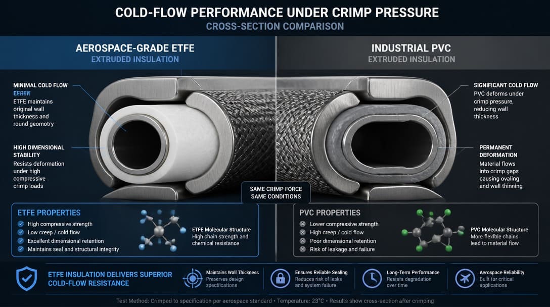
Insulation cold-flow resistance. At the wire-to-contact interface, the insulation is under constant mechanical pressure from the crimp barrel and the connector grommet. Materials like ETFE and radiation-crosslinked PTFE resist cold-flow deformation. Industrial PVC or irradiated PVC — found in commercial off-the-shelf wire — deforms over time, loosening the environmental seal and exposing the conductor to moisture and contamination.
Plating systems and tin whiskers. Connector series from Hirose, JST, or TE Connectivity must be validated not only for pin count and current rating but for the full plating stack. A nickel barrier underplate with a gold flash over the mating surface prevents tin whisker growth, a documented failure mechanism in aerospace electronics where pure tin plating can grow conductive filaments that bridge adjacent pins. Commercial connectors with bright tin plating, even when the form factor matches, introduce a risk that aerospace qualification programs explicitly reject.
The Gap Between Assembled Aerospace Parts and a Certifiable Harness
A harness built from genuine MIL-spec wire, branded connectors, and nomex lacing tape is not automatically certifiable. What separates an assembly from a certifiable product is the documentation and test evidence trail.
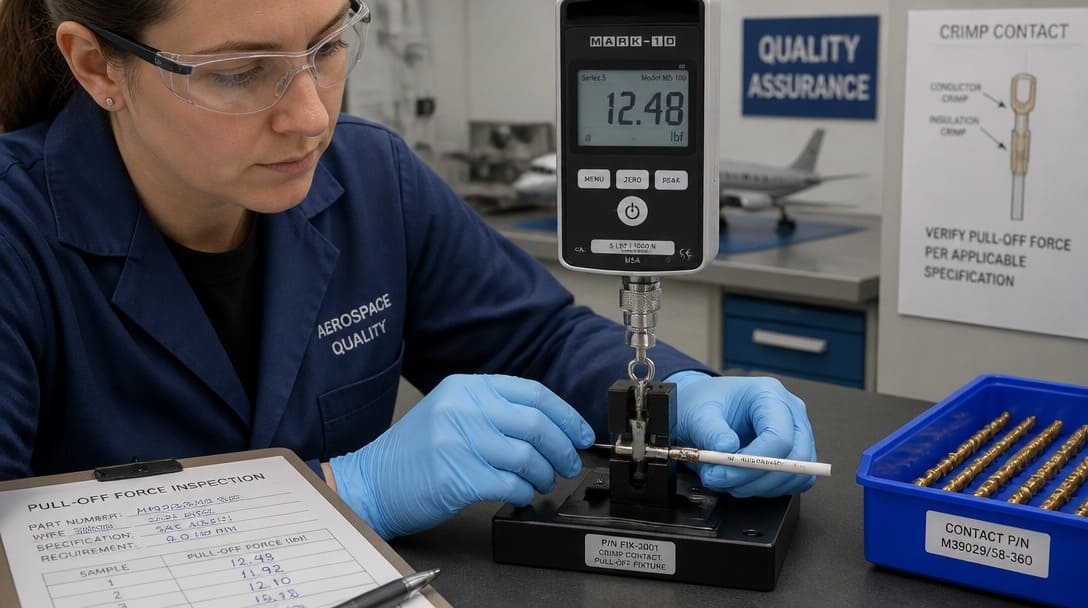
Documentation requirements begin with raw material certificates of conformance that trace back to the manufacturer’s heat or lot number for every wire, contact, connector component, and insulating material in the bundle. First-article inspection reports capture dimensional data, crimp pull-off force measurements, and photographic evidence of the assembly against the drawing. If a single lot number change occurs during production, the traceability chain must record it.
Acceptance testing per EIA-364 (for connector-level electrical tests) and AS50881 (for harness-level verification) typically includes four baseline measurements:
- Continuity — verifying every conductor path from pin to pin with no opens or high-resistance connections.
- Insulation resistance (IR) — measuring the resistance between adjacent conductors and between conductors and shield/ground at the specified voltage, often in the hundreds of megohms or higher.
- Dielectric withstanding voltage (DWV) — applying a high potential between conductors to verify that insulation can withstand voltage transients without breakdown.
- Weight verification — confirming the harness mass matches the design value, a critical parameter in weight-sensitive aerospace programs.
A harness that passes a handheld continuity checker on the bench but lacks serialized test records and signed inspection sign-offs cannot be substantiated during an audit, a customer source inspection, or a qualification review. The evidence trail is part of the deliverable.
Suppliers experienced in wire harness manufacturing for demanding environments understand that the test report is not a formality — it is the document that proves the assembly was built and verified to the control drawing, and it must survive scrutiny years after delivery.
Pre-Order Verification Checklist: 6 Must-Checks Before You Commit
Before releasing a purchase order for an aerospace cable harness, engineers and procurement teams should walk through these six verification steps. Each one addresses a failure mode that commonly emerges only during qualification testing or, worse, in service.
| # | Verification Point | What to Confirm |
|---|---|---|
| 1 | Bend radii and clamping points | Verify routing matches the installation drawing. Confirm minimum bend radii per AS50881 for each bundle diameter. If possible, validate with a harness mock-up in a representative bay before freezing the form board. |
| 2 | Wire type and gauge environmental qualification | Confirm all wire types and gauges meet the vehicle’s environmental qualification envelope — vibration profile, thermal cycling range, and altitude exposure per DO-160 or the program-specific test plan. A wire rated for 200°C static temperature may not survive 200°C combined with vibration. |
| 3 | Crimp process capability validation | Validate the crimp process for each contact-and-wire combination using pull-off force measurement and visual inspection per SAE AS7928. Verify that the production tooling — not a lab-grade press — produces crimps within the specified process window. |
| 4 | Shield termination method | Confirm the shield termination — solder sleeve, ferrule connection, or shielded backshell — meets the system-level EMI/EMC test plan. A pigtail drain wire that works for a commercial enclosure may introduce unacceptable impedance for an aerospace LRU. |
| 5 | Marking durability | Demand laser-marked heat-shrinkable tubing or adhesive-free sleeving that survives exposure to fuels, hydraulic fluid, cleaning solvents, and thermal stress without legibility loss. Ink-jet printing on PVC sleeving will not meet aerospace traceability requirements. |
| 6 | First-article inspection report | Obtain a first-article inspection report with full dimensional verification, continuity and insulation resistance data, and photographic documentation before production release. This is the go/no-go gate for the production batch. |
Translating Checklist into Production-Ready Harnesses
A checklist is only as effective as the production team that executes against it. Experienced production coordination bridges the gap between a specification and a certifiable harness: drawing review identifies incompatible combinations before cutting begins, connector matching verifies plating compatibility across the entire interconnect chain, and process validation confirms that crimp tooling achieves repeatable results within the required window.
Suppliers such as EDOM Electronics support OEM buyers with requirement review, connector matching, sample coordination, production follow-up, inspection, and export-ready packaging for custom cable assemblies and wire harnesses. When a BOM calls for a MIL-DTL-38999 connector from Amphenol or TE Connectivity alongside industrial-grade heat-shrink, an aerospace-aware production partner flags the inconsistency and proposes compliant alternatives before the first wire is cut. First-article inspection coordination and export packaging designed for fragile connector interfaces become part of a repeatable, certifiable supply chain rather than afterthoughts addressed when a shipment arrives with bent contacts.
Failure Modes in the Field: What Goes Wrong When Rules Are Skipped
Aerospace harness failures share a common pattern: the assembly passed its bench tests but failed in an environment that the design did not anticipate. Here are five failure modes that trace directly back to design or process decisions made before the harness left the shop.
Chafing-induced arcing. A harness routes too close to a structural rib without adequate clamping. Under vibration, the outer jacket wears through over weeks of flight hours. Once the conductor insulation is exposed, arcing to the airframe begins. The continuity check passed at the factory; the routing did not survive the installation environment.
Insulation cracking at low temperatures. A wire jacket rated for -40°C is installed in a fuel tank boot where soak temperatures reach -55°C at altitude. The jacket embrittles, cracks at a flex point, and the exposed conductor shorts to structure. The rating on the datasheet was close — but not close enough for the actual thermal envelope.
Tin whisker risks. A commercial off-the-shelf connector with bright tin-plated contacts is substituted because the form factor and pin count match the aerospace part. Over months, tin whiskers grow from the plating surface and bridge adjacent pins, causing intermittent short circuits that are notoriously difficult to diagnose. The connector fit the drawing physically; the plating system was never reviewed.
Wire fatigue at fixed-to-flex transitions. A bundle exits a bulkhead connector and turns sharply into an equipment bay without a strain relief or service loop. After hundreds of thermal cycles and vibration hours, strands begin to fracture at the crimp barrel. The crimp was good; the mechanical transition was not designed for fatigue life.
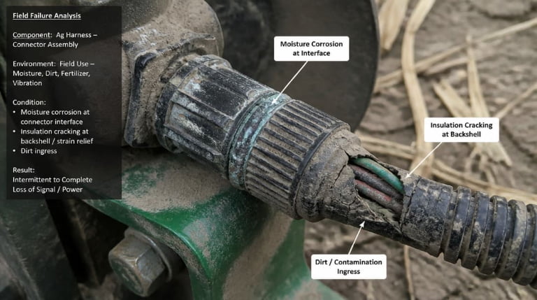
Moisture wicking under non-sealed boots. An environmental seal fails not at the connector interface but because capillary action draws moisture under an unsealed backshell boot. Condensation accumulates, corrosion initiates inside the connector, and insulation resistance degrades over time. The connector was environmentally rated; the boot installation was not.
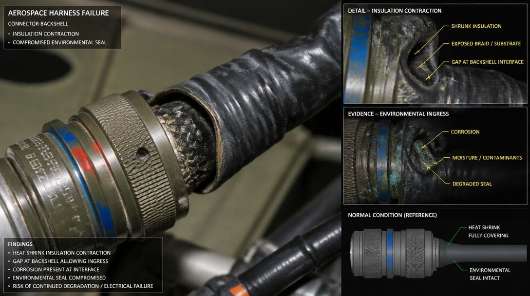
We have seen harnesses that pass a continuity test in the shop but fail after 10 thermal cycles — the wire insulation contracted at the connector grommet because the contractor did not follow the assembly sequence in the control drawing. The crimp was good; the environmental seal was not.
From Harness to System Integration: Next Steps and Resources
An aerospace cable harness is only one element in the interconnect system. The connectors at each end determine how the harness integrates with avionics boxes, power distribution units, and sensor suites. The mechanical fixings — backshells, strain reliefs, and bulkhead gland plates — determine whether the installation survives the airframe’s thermal and vibration environment.
For the broader assembly context — how harnesses integrate with connectors, mechanical fixings, and system-level qualification — see the pillar guide covering aerospace cable assembly specifications and integration practices.
Frequently Asked Questions
What standard governs aerospace cable harness design?
AS50881 is the primary wiring design and installation standard for aerospace vehicles. It covers routing, clamping, bend radii, and installation practices. Supplementary documents including MIL-HDBK-522 (wiring design guidelines), MIL-STD-704 (power quality), and DO-160 (environmental testing) define additional performance requirements that shape harness design.
Can I use industrial-grade heat-shrink on an aerospace harness?
Generally no. Industrial-grade heat-shrinkable tubing often fails outgassing requirements under NASA or ESA standards and may not provide the cold-flow resistance needed at wire-to-contact interfaces. Aerospace harnesses typically require radiation-crosslinked materials with certified outgassing properties and documented lot traceability. A supplier experienced in aerospace requirements can identify incompatible materials during drawing review.
What documentation is required for a certifiable aerospace harness?
A certifiable harness requires raw material certificates of conformance traceable to manufacturer heat or lot numbers, first-article inspection reports with dimensional data and crimp pull-off force measurements, and serialized acceptance test data covering continuity, insulation resistance, dielectric withstanding voltage, and weight verification. Without this evidence trail, the harness cannot be substantiated during audit or qualification review.
How do I verify that a supplier’s crimp process meets aerospace requirements?
Request crimp pull-off force data for each contact-and-wire combination used in the harness, measured against the criteria in SAE AS7928. Verify that the production tooling — not a laboratory press — was used for the samples. A credible supplier will provide this data as part of the first-article inspection report and will have process controls in place to maintain crimp quality across the production batch.
What is the difference between an aerospace harness built to print and one that is certifiable?
An aerospace harness built to print matches the drawing dimensions and uses the specified part numbers. A certifiable harness adds three layers: full lot-traceable documentation, acceptance test data per EIA-364 and AS50881, and process validation records that prove the assembly methods meet the required standards. The physical product may look identical; the difference is the evidence that proves it was built correctly.
Key Takeaways
- AS50881 governs the complete harness, not just the components. An airworthy harness must comply with routing, clamping, and securement rules — not simply use MIL-spec wire and connectors.
- Material compatibility reviews must extend beyond the BOM’s major items. Outgassing, dissimilar metal corrosion, plating system compatibility, and insulation cold-flow resistance all determine whether a harness survives its operational environment.
- Documentation is a deliverable, not an afterthought. Lot traceability, first-article inspection reports, and acceptance test data are as critical to certification as the physical assembly.
- Crimp validation must use production tooling, not laboratory equipment. The process window achieved on the shop floor determines field reliability; SAE AS7928 provides the pull-off force and visual inspection criteria.
- Pre-order verification catches failures before they reach qualification testing. The six-point checklist — covering bend radii, environmental qualification, crimp validation, shield termination, marking durability, and first-article inspection — identifies gaps that bench testing alone will miss.
For OEM buyers and engineering teams translating aerospace specifications into production-ready harness assemblies, explore how to vet custom cable assembly suppliers that support drawing review, connector matching, sample coordination, and production follow-up.