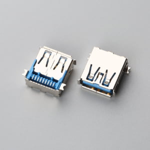
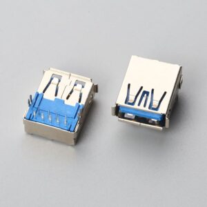
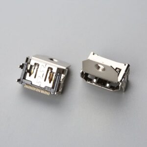
Direct Answer: An aerospace cable assembly is a complete interconnect system—connectors, wire, backshells, and protection—engineered to meet environmental, mechanical, and electrical requirements far beyond commercial-grade products. The most common sourcing failure is not choosing the wrong connector series; it’s choosing a connector that matches the drawing but fails during production because its termination method, plating stack, or mechanical retention was designed for a different assembly process than the one running on the production floor.
Why Pin Count and Physical Fit Are Not Enough
Dimensional match—same number of contacts, same housing shape, same pitch—creates a powerful illusion of compatibility. A connector that mates physically with its counterpart on the bench passes the first visual check. Purchase orders get released. Inventory moves into the production queue.
Then the problems surface. A crimp tool set for a specific wire gauge range produces inconsistent pull-force values because the terminal was engineered for a different barrel design. A wave-soldering profile that works perfectly for the original connector lifts pads on the substitute because its thermal mass and lead coplanarity differ. A connector that fit the mating face perfectly on the bench disconnects intermittently under vibration because its latch spring force is lower than the original specification demanded.
These failures share a common root cause: the connector was evaluated against the drawing, not against the process it would encounter in production. For aerospace applications—where cable assemblies must perform across temperature extremes, vibration profiles, and extended service intervals—this gap between dimensional fit and process compatibility becomes a reliability risk, not just a production inconvenience.
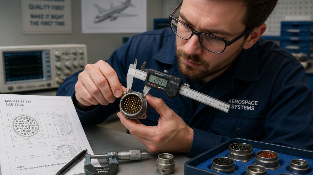
Deciphering the Connector Name: Brand, Series, and Generic Equivalents
A connector part number on an aerospace BOM or wiring diagram carries more information than most buyers realize. The prefix or series designation identifies not just a physical shape but an entire engineering ecosystem: the contact design philosophy, the plating specification range, the tooling family, and the testing heritage.
Major aerospace connector manufacturers—such as Amphenol, TE Connectivity (DEUTSCH), Souriau, and ITT Cannon—each maintain proprietary internal standards that often exceed baseline military specifications. For instance, while two MIL-DTL-38999 connectors from different vendors might share the same insert arrangement and shell size, their proprietary interfacial seal geometries, EMI grounding fingers, and plating adhesion processes can vary significantly. A commercial off-the-shelf (COTS) equivalent might mate physically on the bench, but fail catastrophically under DO-160 vibration testing due to inferior contact retention mechanisms.
The table below illustrates how these mission-critical engineering differences manifest across standard aerospace connector families:
| Brand / Standard | Example Series | Known For | Critical Aerospace Considerations |
|---|---|---|---|
| Amphenol / Glenair | MIL-DTL-38999 Series III | Harsh environment circular connectors, triple-start thread | Shell plating (Cadmium vs. Nickel PTFE), EMI grounding fingers |
| TE DEUTSCH | EN2997, AS39029 Contacts | High vibration, firewall, and engine applications | Interfacial seal integrity, rigorous contact retention force |
| Souriau (Eaton) | ARINC 600 | Avionics rack and panel rectangular connectors | Insert arrangements, blind-mate tolerances, and polarization |
| ITT Cannon | Micro-D (MIL-DTL-83513) | High-density space-grade interconnects | Outgassing compliance (ASTM E595), jackpost hardware |
Knowing the original manufacturer’s name and series is the starting point for any accurate sourcing exercise. A generic term—”2.5mm pitch locking connector”—may describe a dozen incompatible product families. Without tracing the designation back to its origin, the buyer is navigating by shape alone.
Aerospace Wire, Cable, and Environmental Standards: The Overlooked Core
While connectors often get the spotlight, the actual wire and shielding define an aerospace cable assembly’s survivability. Commercial PVC or standard polyurethane jackets will fail catastrophically under flight conditions.
Flight-critical wire is typically specified to standards like SAE AS22759 (often utilizing PTFE, ETFE, or cross-linked insulation), which provides exceptional resistance to abrasion, cold-flow, and chemical exposure (such as Skydrol hydraulic fluids). For multi-conductor configurations, NEMA WC 27500 dictates how these internal wires are twisted, shielded, and jacketed to form a complete aerospace cable.
Furthermore, an aerospace assembly isn’t qualified just because it passes a continuity test. It must be engineered to survive the environmental baselines set by RTCA DO-160 (for commercial aviation) or MIL-STD-810 (for defense). These standards dictate grueling test profiles for:
- Temperature & Altitude: Rapid depressurization and extreme thermal shock (-65°C to +200°C+).
- Vibration & Shock: Sustained engine-zone frequencies that cause standard contacts to experience fretting corrosion.
- EMI/RFI Susceptibility: Requiring heavy braided shielding (like tinned copper or lightweight composite braids) terminated perfectly to the connector backshell via banding or soldering.
While NEMA WC 27500 dictates how internal wires form a complete aerospace cable, routing these components across an entire airframe introduces another layer of complexity. If your project involves point-to-point branches, open bundle breakouts, and preparation for supplier quotation, consult our comprehensive guide on wire harness aerospace applications and requirements to align your BOM and drawings. Furthermore, the core engineering principles of surviving severe environments—chemical exposure, high-pressure washdown, and persistent vibration—are equally vital for heavy off-highway machinery. To explore how these harsh-environment interconnect strategies apply to heavy machinery, read our detailed guide on Agriculture Wiring Assemblies: What OEM Buyers Need to Know. For airframe-specific integration rules, see our guide on Understanding Aircraft Wiring Harness Design and Manufacturing Standards.
Termination Method: The First Production Bottleneck
Termination compatibility separates connectors that work from connectors that create rework. Every connector is designed for one or more specific termination methods—crimp, solder, insulation displacement—and each method imposes its own constraints.
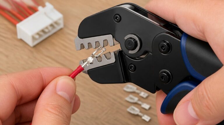
For crimp-type connectors, the terminal barrel is engineered for a defined wire gauge range. Using wire outside that range—too large, and the barrel cannot deform correctly around the conductor strands; too small, and the crimp fails to achieve adequate mechanical grip—produces inconsistent conductivity and terminal pull-out under mechanical load. The UL listing for the connector-terminal combination validates performance within specific wire gauge boundaries; stepping outside those boundaries voids the recognized performance envelope.
For aerospace circular connectors involving solder cup terminations or shield grounding, the process window is strictly governed by standards like IPC J-STD-001 Space Addendum. Operators must ensure flawless wetting without wicking solder under the wire insulation—a defect that creates a hard stress-riser highly susceptible to vibration fatigue. Furthermore, unlike commercial industries driven by RoHS, many flight-critical and space-grade assemblies strictly require leaded solder (SnPb) to completely eliminate the risk of tin whiskers, which can cause catastrophic short circuits in a vacuum.
Ultimately, specifying the right termination method, plating, and wire standard is only the engineering half of the equation. Transitioning these strict requirements from a drawing into a physical, repeatable product requires a highly capable manufacturing partner. If you are struggling to find a supplier who truly understands AS9102 First Article Inspections, specialized DMC tooling, and strict material traceability, read our comprehensive guide on Aerospace Cable Manufacturers: What OEM Buyers Need to Know to learn how to properly evaluate and audit your supply chain.
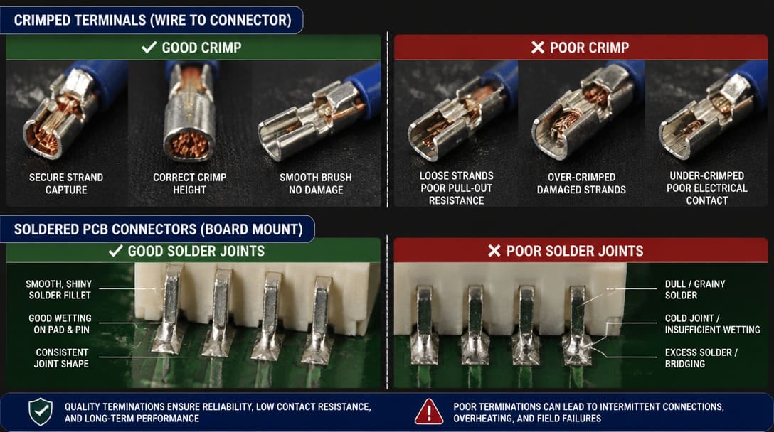
We regularly see connectors that pass visual incoming inspection but fail during assembly—the termination interface or plating stack was engineered for a different process than the one running on the production line. For mission-critical applications, physical mating is meaningless if the termination violates IPC/WHMA-A-620 Class 3 (or the Space Addendum) standards.
Under Class 3 requirements, crimp joints must undergo strict crimp height and pull-force verification, and soldered terminations demand flawless wetting and zero micro-voiding. A substitute part that alters the terminal’s deformability or thermal mass can cause catastrophic under-crimping or cold solder joints. These defects often pass ambient bench testing, yet fail catastrophically under flight vibration due to micro-fretting. In aerospace manufacturing, process validation is just as critical as the part itself.
When transitioning from prototype designs to full production, evaluating assembly capabilities and choosing between regional or overseas manufacturing partners is critical. For a detailed decision framework on local supplier verification, read our guide on Wire Harness Manufacturing Near Me: 5 Factors to Evaluate.
Plating Material and Thickness: The Corrosion and Solderability Factor
Contact plating is not decorative. It governs three performance parameters that drawings rarely specify in full: contact resistance stability, mating-cycle durability, and resistance to environmental degradation.
Gold flash—thin gold deposited directly over nickel underplate—provides a low-resistance interface and protects against oxidation, but its thickness (often 0.025 to 0.05 microns) limits its durability to lower mating-cycle counts. Selective gold plating—thicker gold, typically 0.75 microns or more, applied only in the contact zone—extends the cycle life to hundreds or thousands of matings. The difference in cost is significant; the difference in aerospace application suitability can be decisive.
EIA-364 test standards define the methods for evaluating plating integrity: adhesion testing (EIA-364-29), porosity testing (EIA-364-53), corrosion resistance (EIA-364-26), and durability cycling. A connector that has been qualified to these standards under a specific plating specification carries a verified performance envelope. A generic substitute with visually similar gold plating but no test documentation may have thinner gold, higher porosity, or a different nickel underplate thickness—differences invisible to the naked eye.
For connectors destined for aerospace cable assemblies, plating thickness measured in microinches separates parts that survive 500 mating cycles from parts that develop high-resistance contacts after 100 cycles. This matters especially in engine compartment, wing leading-edge, or unpressurized bay installations where temperature swings and condensation accelerate fretting corrosion.
| Plating Type | Typical Thickness | Mating Durability | Aerospace Suitability |
|---|---|---|---|
| Gold flash over nickel | 0.025–0.05 µm Au | ~50–100 cycles | Limited; low-cycle applications only; prone to porosity issues in harsh environments. |
| Selective hard gold | 0.75–1.25 µm Au | 500+ cycles | Preferred for high-reliability signal and power interconnects. |
| Matte tin over nickel | 2.5–5.0 µm Sn | ~25–50 cycles | Prohibited in high-reliability aerospace/space environments due to catastrophic tin whisker risks in vacuum and vibration. |
| Silver (with anti-tarnish) | 2.0–5.0 µm Ag | ~100–250 cycles | Used in high-temperature RF applications; subject to strict atmospheric control to prevent Red Plague corrosion. |
The “Red Plague” and Outgassing Risks in Aerospace Sourcing
When specifying contact platings, engineers must look beyond basic wear-cycle limits.
- Red Plague (Cuprous Oxide Corrosion): In aerospace cable assemblies, silver-plated copper conductors are highly valued for their superior conductivity at high temperatures. However, if the silver plating is too thin, porous, or damaged during stripping, exposure to moisture and oxygen initiates electrochemical galvanic corrosion. This forms cuprous oxide (known as “Red Plague”), which can silently degrade the copper core and lead to catastrophic wire fatigue.
- Outgassing (ASTM E595): Connectors and cable jackets destined for high-vacuum space environments or unpressurized avionic bays must meet strict vacuum outgassing requirements. Materials used in insulators, grommets, and heat-shrink boots must be certified to ASTM E595 (with Total Mass Loss ≤ 1% and Collected Volatile Condensable Material ≤ 0.1%) to prevent outgassed compounds from condensing on sensitive optical sensors and circuit boards.
Mechanical Retention: Board Locks, Anchors, and Latches
In aerospace cable assemblies, vibration is not an edge case—it is a continuous operating condition. Connector retention features determine whether the interconnect system maintains electrical continuity through thousands of hours of broadband vibration, shock pulses, and thermal expansion cycles.
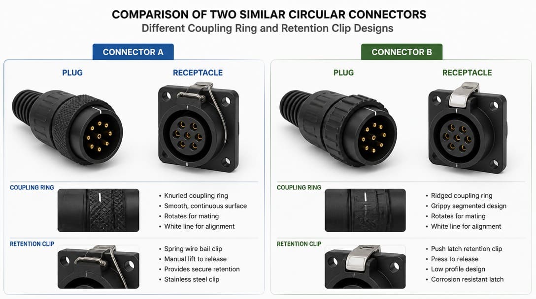
Integral board locks—metal tabs formed into the connector housing or inserted as separate spring members—anchor surface-mount connectors to the PCB, transferring mechanical load away from the solder joints. Through-hole solder anchors provide even stronger retention by engaging the plated through-hole barrel. Positive-latch mechanisms on wire-to-wire and wire-to-board connectors prevent gradual walk-out under axial cable load and vibration.
TE Connectivity and Amphenol, both with extensive aerospace connector portfolios, implement retention features that are integral to their product qualification programs. The DEUTSCH series (TE) and MIL-DTL-38999 derivatives (Amphenol) include interfacial seals, coupling rings with defined torque values, and contact retention clips tested to specific force and cycle requirements per EIA-364-38 (contact retention) and EIA-364-27 (mechanical shock).
A substitute connector may have a latch that looks similar in photographs but delivers lower spring force, smaller engagement depth, or thinner retention tang material. Only side-by-side sample evaluation against the original specification—measuring insertion force, withdrawal force, and latch deflection—can confirm equivalent mechanical retention.
Compatible vs. Interchangeable—What the Drawing Won’t Tell You
The distinction between “compatible” and “interchangeable” is the most expensive vocabulary lesson in connector sourcing.
- Compatible means two connectors can be physically mated. The contact arrangement, polarization, and keying allow mechanical engagement without damage.
- Interchangeable means two connectors are fully equivalent in form, fit, and function. They share the same termination method envelope, the same plating specification, the same mechanical retention characteristics, and the same performance across the full range of environmental conditions specified for the application.
A connector may be compatible at the mating interface but fail to meet the original system’s termination, plating, or retention specs. This creates a latent failure risk: the assembly passes final inspection, ships to the customer, and operates normally for weeks or months before an intermittent disconnect appears under vibration or thermal cycling.
Verifying interchangeability requires comparing the complete bill of materials and test reports to the original specification. The outline drawing tells you whether two connectors will mate; only the full engineering documentation—material declarations, plating thickness certificates, test reports per EIA-364 methods, and process capability data for the production line—tells you whether they will perform identically over the system’s service life.
The table below summarizes the evaluation dimensions:
| Evaluation Dimension | Compatible | Interchangeable |
|---|---|---|
| Mating interface geometry | Yes—physical engagement possible | Yes—identical contact geometry, polarization, keying |
| Termination method match | Not guaranteed—may require process change | Yes—same wire gauge range (crimp) or solder profile window (PCB) |
| Plating specification | Not guaranteed—may differ in thickness or alloy | Yes—same material, thickness, and underplate structure |
| Mechanical retention | Not guaranteed—latch force or anchor design may differ | Yes—identical retention features and force values |
| Environmental qualification | Not guaranteed—test reports may not match | Yes—same test methods, conditions, and acceptance criteria |
Pre-Order Verification Checklist for Connector Sourcing
Before committing to a purchase order, engineering and procurement teams should verify four categories of connector compatibility that go beyond the outline drawing. This checklist applies whether the connector is for aerospace, industrial, or automotive applications.
-
- Confirm termination method matches your assembly process. For crimp-type connectors, verify the wire gauge range specified for the terminal and confirm your crimp tooling and die set are compatible with the terminal barrel design. For PCB-mount connectors, obtain the recommended solder profile (reflow or wave) and pad layout tolerance, and compare against your production line’s calibrated parameters.
- Check plating specification against environmental and mating-cycle requirements. Request the plating material declaration, thickness data (including underplate), and RoHS compliance certificate. Verify that the gold thickness, nickel underplate, and any selective plating zones meet the durability and corrosion requirements (and do not introduce Red Plague risks on silver-plated wire).
- Verify key dimensions with actual physical samples. Datasheet drawings are nominal representations. Obtain physical samples and measure critical retention features—latch engagement depth, board lock standoff height, coupling ring thread engagement—under the same conditions your incoming inspection process will use. Whenever possible, test mating force and withdrawal force against the original specification or a known-good reference part. For more on how sample evaluation integrates with production quality gates, see the quality inspection and export packaging support available for OEM cable assembly programs.
- Confirm the mating interface is fully identical. Contact geometry, polarization features, and keying must match the original part exactly. Even a slight difference in keying rib position or contact alignment can prevent full engagement or cause contact damage during mating.
- Verify Quality Management & Process Traceability. For flight-critical systems, OEM buyers should demand AS9100D-level process controls or strict ISO 9001 traceability. Confirm that your manufacturing partner can provide a complete Certificate of Conformance (CoC) and establish full material lot traceability from the raw wire to the finished harness, adhering to IPC/WHMA-A-620 Space Addendum requirements.
- Ensure complete technical package availability. Before releasing the PO, provide the supplier with the Interface Control Drawing (ICD), wiring schematic, harness routing constraints (AS50881 compliance), and specific electrical test requirements (hipot, insulation resistance, and continuity).
From Connector Selection to Aerospace Cable Assembly Integration
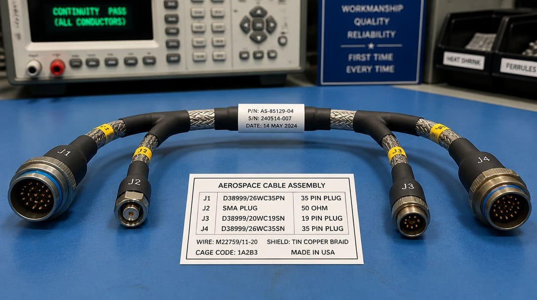
Correct connector specification is the foundation; building a reliable aerospace cable assembly requires translating that component choice into controlled production processes. Crimping force must be monitored per terminal family specifications. Cable routing must avoid tension at connector backshells, maintain minimum bend radii, and provide strain relief appropriate to the vibration environment. Continuity testing and insulation resistance measurement—conducted at multiple stages including after connector termination and again after final assembly—catch defects that visual inspection misses.
360-Degree EMI/RFI Shielding and Protective Backshells
An aerospace wire harness is rarely a collection of bare wires; it must operate in dense electromagnetic environments without emitting or receiving interference.
True aerospace-grade integration requires robust electromagnetic interference (EMI) and radio frequency interference (RFI) shielding. This is achieved by terminating metal braided shielding (such as tin-copper or nickel-copper braids) directly to the connector backshell using a 360-degree compression band (e.g., Band-It bands) or overmolding. A simple pigtail shield termination is a major point of failure under Class 3 standards because it creates an inductive loop, allowing RF leakage. Additionally, shielding must be protected by aerospace-grade braided sleeving or military-spec heat-shrink boots to withstand fluid exposure and abrasive routing friction.
Aerospace cable assemblies sit at the intersection of connector-level specs and harness-level requirements. UL-recognized components and RoHS-compliant materials are baseline expectations for export-ready assemblies, but they do not replace project-specific verification. The same harness that passes bench testing at room temperature may develop intermittent opens at altitude when connector contact resistance shifts with thermal contraction. For a deeper look at production coordination, routing, labeling, looming, and final inspection, explore how structured wire harness manufacturing processes turn connector selection decisions into production-ready assemblies.
When the connector puzzle is solved, the next question procurement teams face is how to source the complete assembly with consistent quality across production batches. Electronic connector selection, specification review, and supply coordination form the bridge from component to production—and getting that bridge right determines whether the assembly performs to specification over its full service life.
Once you have validated the connector specifications, integrating them into a compliant system requires strict adherence to routing and material standards. For a deeper dive into AS50881 rules and OEM compliance, read our complete guide on aerospace cable harness design and sourcing considerations.
Frequently Asked Questions
What makes a connector “aerospace-grade” versus commercial-grade?
Aerospace-grade connectors are qualified to much wider temperature ranges (typically -65°C to +200°C for MIL-DTL-38999 types), tighter contact resistance stability requirements, stringent outgassing limits (ASTM E595), and severe vibration/shock profiles without fretting or intermittent disconnection.
Why is IPC/WHMA-A-620 Class 3 mandatory for aerospace cable assemblies?
Class 3 represents the highest level of performance for high-reliability electronics. In aerospace applications, it mandates zero-defect criteria for crimp heights, pull-force verification, zero solder wicking under insulation, and 100% material traceability to prevent in-flight vibration failures.
Can I use a generic equivalent connector if the pin count and pitch match?
Pin count and pitch match are necessary but insufficient conditions. The termination method (crimp wire gauge range or solder profile window), plating thickness and material, mechanical retention features, and environmental qualification must all be verified against the original specification. A generic equivalent that mates physically may fail during production because your crimp tooling, soldering process, or test procedure was set up for a different connector engineering design.
How do I verify plating quality before placing a production order?
Request the plating material declaration and thickness certificate from the connector supplier or distributor. For aerospace applications, specify the relevant EIA-364 test methods for adhesion, porosity, and corrosion resistance, and request evidence of compliance. Physical sample evaluation—including cross-sectioning for plating thickness measurement—provides definitive data but adds time and cost; reserve this step for critical connectors or new supplier qualifications.
What should I include in a connector RFQ to avoid compatibility problems?
An effective connector RFQ should include: the original manufacturer part number and series designation, the wire gauge range (for crimp types) or soldering process parameters (for PCB types), the required plating specification with thickness, the environmental operating conditions (temperature range, vibration profile, exposure to fluids), and any retention feature requirements (latches, board locks, coupling mechanisms). Providing the end-use context—aerospace cable assembly, engine compartment, avionics bay—helps suppliers identify whether their offering is compatible or merely dimensionally similar.
Key Takeaways
- Dimensional match—same pin count, same housing shape—does not guarantee production compatibility. Termination method, plating stack, and mechanical retention are the parameters that determine whether a connector works in your assembly process and survives in service.
- Brand and series designations (Molex, TE Connectivity, JST, Amphenol, Hirose) encode engineering decisions about contact design, tooling family, and qualification testing that generic equivalents may not replicate.
- “Compatible” means two connectors mate; “interchangeable” means they are fully equivalent in form, fit, and function across all termination, plating, and retention parameters. The gap between the two is where latent field failures originate.
- A four-point pre-order verification checklist—termination method, plating spec, physical sample measurement, mating interface identity—catches most connector sourcing errors before they reach the production floor.
- Correct connector selection is the first step; translating it into a reliable aerospace cable assembly requires controlled crimping, routing, testing, and inspection processes that suppliers with coordinated production support can provide.
When the connector puzzle is solved, the next challenge procurement and engineering teams face is how to source the complete assembly with consistent quality across production batches.
At EDOM Electronics, our build-to-print production lines adhere strictly to IPC/WHMA-A-620 Class 3 standards, backed by our robust AS9100D quality management system. From micro-inch plating thickness verification and ASTM E595 outgassing compliance to 360-degree EMI shielding and 100% automated electrical testing (including DWV and insulation resistance), we ensure your aerospace interconnect systems operate flawlessly in the harshest environments.