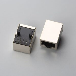
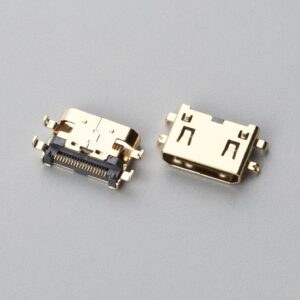
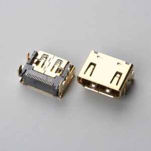
The golden sample trap in custom wire harness manufacturing occurs when an approved prototype—often hand-built under optimal lab conditions—passes visual and basic continuity checks, but subsequent mass-production batches suffer high failure rates due to tooling degradation, process drift, or component substitutions.
To bridge this gap, OEM procurement teams and quality engineers must enforce three engineering release gates:
- Tooling & Process Lock: Verify prototypes are produced on production-grade semi-automatic/automatic applicators, not manual hand crimpers.
- 100% Comprehensive Electrical Testing: Require automated test-board records covering continuity, miswiring, and high-voltage dielectric/insulation resistance (Hipot).
- Statistical Process Control (SPC): Mandate Crimp Force Monitoring (CFM) and crimp cross-section analysis per IPC/WHMA-A-620 Class 2/3 standards.
Golden Sample vs. Mass Production: Where Quality Drifts
A visually flawless prototype does not guarantee production yield. Understanding where bench-built samples diverge from high-speed factory lines is essential to preventing field failures.
| Risk Dimension | Golden Sample (Bench Prototype) | Mass Production Reality | Required Quality Gate |
|---|---|---|---|
| Crimp Consistency | Manually tuned by an engineer; zero tool wear. | High-speed presses run 50,000+ cycles; blade wear causes crimp height drift. | Real-time Crimp Force Monitoring (CFM) & per-shift pull-force verification. |
| Terminal Seating | Careful manual pin insertion with 100% manual tug test. | High-volume assembly fatigue leads to unseated lances and terminal back-out. | Mandatory TPA (Terminal Position Assurance) & tactile/audible click checks. |
| Circuit Integrity | Standard multimeter continuity buzz test. | Potential high-voltage breakdown, micro-shorts, or insulation pinholes under vibration. | 100% automated Hipot / Dielectric Withstand & Insulation Resistance testing. |
| Raw Material Consistency | Genuine brand connectors (JST, Molex, TE) used for sample sign-off. | Risk of unapproved cross-series clones or batch resin tolerance shifts. | Strict Approved Vendor List (AVL) lock & raw material lot traceability. |
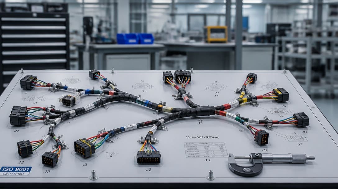
Technical RFQ Parameters That Prevent Production Deviations
Specifying only wire gauge and length allows suppliers to make unverified assumptions. An engineering-grade RFQ package must freeze critical specifications early:
- Conductor & Insulation: Specify strand count, conductor plating, insulation type (PVC, XLPE, Teflon), and exact UL 758 AWM style (such as UL 1007 or UL 1569) with temperature/voltage ratings.
- Terminal & Housing MPNs: Provide exact manufacturer part numbers (MPNs) and contact plating specifications (e.g., selective gold over nickel vs. tin).
- Workmanship Classification: Explicitly specify IPC/WHMA-A-620 Class 2 (Standard Commercial) or Class 3 (High-Performance / Harsh Environment).
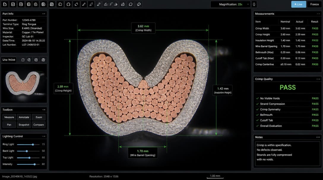
The Engineering Gaps That Cause Mass-Production Drift
Even with a signed-off golden sample, production units can fail in the field if process parameters are not locked during mass manufacturing. The three primary failure modes include:
- Tooling Wear and Crimp Drift: Prototype terminals are typically crimped on newly set-up dies. Over runs of 50,000+ cycles, applicator punch blades wear down, shifting Conductor Crimp Height (CCH) out of tolerance and causing micro-arcing or high contact resistance.
- Operator Fatigue & Terminal Back-Out: In bench prototyping, technicians manually verify terminal latch engagement. In high-volume manual insertion, unseated terminal lances slip past visual inspection unless secondary locking mechanisms like Terminal Position Assurance (TPA) are enforced.
- Component Tolerance Variance: Batch-to-batch inconsistencies in alternative housing resin or unapproved wire strand plating lead to intermittent contact under thermal expansion and vibration.
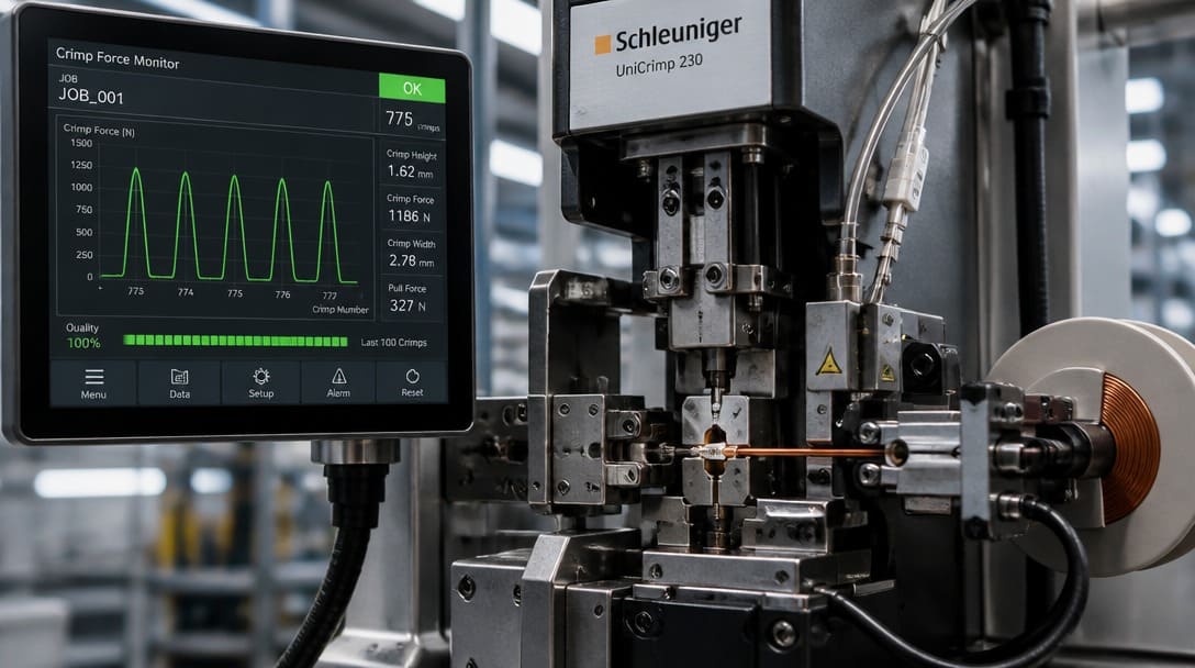
Mass-Production Quality Gate Matrix: From Prototyping to Full Run
To prevent quality degradation after sample approval, every production stage must enforce strict statistical controls:
| Production Stage | Critical Failure Risk | Manufacturing Defense Mechanism | Verification Standard |
|---|---|---|---|
| Wire Cutting & Stripping | Nicked/cut strands, uneven strip length | Automated rotary stripping with laser vision inspection | Zero broken strands per IPC/WHMA-A-620 Class 3 |
| Terminal Crimping | Loose crimp, void formation, wire pull-out | Continuous Crimp Force Monitoring (CFM) & hourly micrometer logs | Cpk >= 1.33, UL 486A tensile pull test |
| Housing Insertion | Terminal back-out, unseated locking tangs | 100% mechanical pull-back check + mandatory TPA insertion | Audible/tactile lock verification |
| Harness Testing | High-voltage flashover, insulation punctures | Programmable automated test board with Hipot & IR test | 500V DC, IR >= 100 MΩ, leakage <= 0.5 mA |
| Packaging & Transit | Pin bending, contact oxidation, cable fatigue | Controlled packaging bend radius, sealed moisture-barrier desiccant bags | Visual inspection & environmental packaging check |
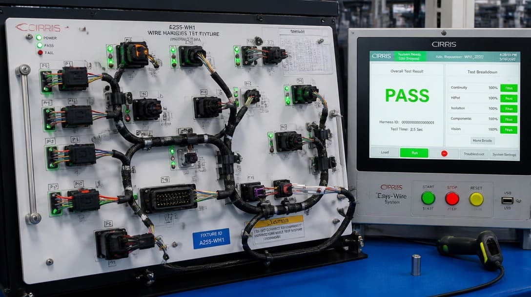
OEM Supplier Audit Checklist: Verifying Mass-Production Readiness
Before releasing production POs based on an approved sample, evaluate the supplier’s shop-floor capabilities using this checklist:
- [ ] Automated Applicators with CFM: Ensure terminals are crimped using semi-automatic/automatic presses fitted with real-time Crimp Force Monitors that stop the machine on pressure anomalies.
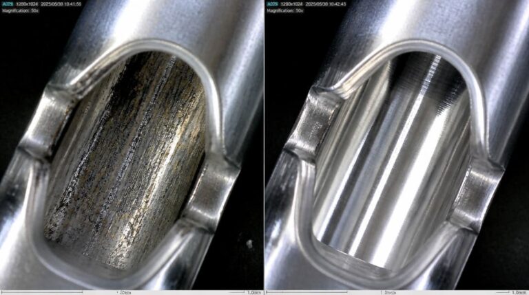
- [ ] Micrographic Cross-Section Lab: Confirm the factory has an in-house crimp cross-section analysis system to inspect core compaction, crimp symmetry, and strand deformation.
- [ ] Dedicated Circuit Test Boards: Verify that final testing uses customized wiring harness test fixtures (e.g., Cirris or computerized wire testers) rather than manual hand-held multimeters.
- [ ] Calibration & Tooling Logs: Review maintenance records for wire strippers, crimp dies, and tensile testers to ensure tools are calibrated at regular cycle intervals.
- [ ] Strict AVL & Traceability: Ensure all raw materials (wire spools, connector housings, terminals) have traceable lot numbers matching the approved First Article Inspection (FAI) package.
Quality Verification Checklist Before Production Sign-Off
To ensure the high-volume production batch matches the approved First Article Inspection (FAI) sample, enforce the following five mandatory release gates:
- Crimp Geometry & Micrographic Cross-Section: Conductor Crimp Height (CCH) and Insulation Crimp Height (ICH) must fall within +/-0.03 mm of terminal engineering specifications. Cross-section analysis per IPC/WHMA-A-620 Class 3 must confirm void-free compaction, symmetrical crimp wings, and zero strand degradation.
- Mechanical Retention (Tensile Pull-Out Testing): Execute pull-force verification per UL 486A-486B or SAE/USCAR-21 (e.g., minimum 35.6 N / 8 lbf for 22 AWG; minimum 89 N / 20 lbf for 18 AWG).
- 100% Automated Electrical & Hipot Testing: Require computerized test-board verification logs covering:
- Continuity & Miswiring: 100% pinout mapping with no intermittent contacts.
- Insulation Resistance (IR): >= 100 MΩ at 500V DC.
- Dielectric Withstanding Voltage (Hipot): No dielectric breakdown at specified test voltages (leakage current <= 0.5 mA).
- Tooling & Applicator Freezing: Confirm in writing that mass-production runs will utilize the identical semi-automated applicators, crimp dies, and test boards approved during FAI.
- Packaging & Bend Radius Control: Specify minimum bend radius limits during packaging to prevent terminal necking and strain fatigue, supplemented by sealed moisture-barrier packaging for overseas transit.
Engineering Sign-Off: From Prototype Approval to Mass Production
Transitioning from a golden sample to high-yield mass production requires binding engineering agreements rather than verbal assurances. When finalizing the production purchase order:
- Lock the Technical Data Package (TDP): Attach the approved 2D/3D drawings, terminal crimp cross-section reports, and bill of materials (BOM) with frozen Manufacturer Part Numbers (MPNs).
- Mandate Outgoing Quality Control (OQC) Sampling: Require batch release inspection based on ISO 2859-1 (Level II, AQL 0.65 for Major defects, 1.0 for Minor defects).
- Include ECN/PCN Clauses: Prohibit any tooling modification, raw material brand substitution, or line transfer without prior written Engineering Change Notification (ECN) approval.
For turnkey engineering support and automated manufacturing walkthroughs, explore our Wire Harness Manufacturing Services. If you need a comprehensive baseline on design structures, core components, and application architectures before finalizing specifications, refer to our complete pillar guide on What Is a Wiring Harness? Key Components, Functions & Applications.
Frequently Asked Questions
What technical data must be frozen in the RFQ to prevent mass-production drift?
To eliminate supplier assumptions, the RFQ must freeze the approved drawing revision, exact wire construction and insulation type (e.g., UL 1007, UL 1569), genuine connector Manufacturer Part Numbers (MPNs), contact plating thickness, wire harness pinout schematic, and explicit test standards (IPC/WHMA-A-620 Class 2 or Class 3, Hipot voltage, and tensile pull-force thresholds).
How does tooling wear cause intermittent failures in production wire harnesses?
During extended production runs (50,000+ cycles), crimp applicator punch blades experience microscopic wear, gradually shifting the Conductor Crimp Height (CCH) upward. This reduces core strand compaction, leading to elevated contact resistance, micro-arcing, and intermittent open circuits under thermal cycling and mechanical vibration.
What documentation should OEM buyers demand alongside wire harness samples?
OEM buyers should require a comprehensive First Article Inspection (FAI) package, including:
- Dimensional Inspection Report: Validating wire cut lengths, breakout locations, and overall branch tolerances against the approved drawing.
- Crimp Analysis Data: Micrographic cross-section images, Conductor Crimp Height (CCH), Insulation Crimp Height (ICH), and mechanical pull-force test values.
- 100% Electrical Test Certificate: Automated test logs confirming continuity, pinout mapping, Insulation Resistance (IR), and Dielectric Withstanding Voltage (Hipot).
- Certificate of Conformance (CoC) & Material Traceability: Verifying UL recognized wire styles, genuine connector Manufacturer Part Numbers (MPNs), and RoHS/REACH compliance.
What is IPC/WHMA-A-620 and why does it matter for my harness?
IPC/WHMA-A-620 is the global consensus standard for cable and wire harness fabrication. It defines workmanship acceptance criteria across three classes: Class 1 (General Electronic Products), Class 2 (Dedicated Service Electronic Products), and Class 3 (High-Performance / Harsh Environment Electronic Products), establishing clear baseline requirements for crimping, soldering, routing, and testing.
How do OEM buyers prevent the golden sample trap in wire harness sourcing?
To prevent the golden sample trap, OEM buyers must require suppliers to lock the production process at the sample stage:
- Mandate that initial prototypes are produced using production-grade applicators rather than manual hand crimpers.
- Require an FAI report with micrographic cross-section and crimp height/width measurements.
- Require 100% automated electrical test logs covering continuity, miswiring, and high-voltage insulation resistance.
- Freeze the Approved Vendor List (AVL) and enforce strict ECN/PCN agreements to prevent unauthorized component substitutions.
Key Takeaways
- The Golden Sample Gap: Flawless bench-built prototypes often fail in mass production due to tooling wear, assembly fatigue, and unmonitored crimp drift.
- SPC & Tooling Lock: Prevent batch failures by mandating semi-automated applicators with real-time Crimp Force Monitoring (CFM) and Cpk >= 1.33 dimensional verification.
- 100% Comprehensive Testing: Require automated test-board verification that includes Hipot dielectric withstand and insulation resistance (>= 100 MΩ) to catch micro-defects.
- Rigorous FAI Documentation: Sign off on samples only after receiving complete micrographic cross-sections, UL 486A pull-out test data, and material lot traceability records.