2026年8月14日
What Is an RJ45 Connector? Understanding RJ45 Pinout and Uses
What is RJ45 connector? Get pinout details, Ethernet uses, and sourcing specs like plating and termination to avoid...

Rapid Prototyping in 3-5 Days
B2B Electronic Connection Solution
Factory-backed connector sourcing and electric connection support for OEMs, distributors and electronic equipment manufacturers.
OEM Ready
Factory Supply
Fast Quote
Product Specifications
Key parameters for OEM, distributor and engineering evaluation.
Detailed Product Information
Structured parameters, material notes, application context and frequently asked questions for engineering and procurement evaluation.
Intermateable: This part is mechanically and electrically compatible for mating with the listed competitor connector. Mixed use in the same connector system is supported.
| Material | Value / Description |
|---|---|
| Housing & Terminal Bracket | Thermoplastic PBT, UL94 V-0 Rated, Black |
| Contact Material | Phosphor Bronze (Thickness = 0.35mm) |
| Contact Plating | 6u" Gold Plating on Contact Area |
| Shield Material & Plating | Brass (Thickness = 0.20mm), Full Nickel Plating |
| Characteristic | Value |
|---|---|
| Dielectric Withstanding Voltage (Hi-Pot) | 2250V DC for 6 Seconds, 1mA Max. (Primary to Secondary) |
| PoE DC Current & Voltage Rating | 350mA Max. Balanced DC Line Current, 57V DC Continuous |
| Open Circuit Inductance (OCL) | 350uH Min. @ 100kHz, 100mV RMS, 8mA DC Bias (4 Channels) |
| Turns Ratio (TX & RX) | 1CT:1CT (±2%) |
| Insertion Loss | -1.0dB Max. @ 1MHz to 100MHz |
| Return Loss | -20dB Min. (1–10MHz); -16dB Min. (10–30MHz); -12dB Min. (30–60MHz); -10dB Min. (60–80MHz) |
| Crosstalk | -40dB Min. (1–30MHz); -35dB Min. (30–60MHz); -30dB Min. (60–100MHz) |
| Common Mode Rejection (CMR) | -30dB Min. @ 1MHz to 100MHz |
| Wave Soldering Peak Temperature | 260°C ±5°C for 5 Seconds Max. |
| Operating & Storage Temperature | -40°C to +85°C |
| General Tolerances | .X ±0.30mm, .XX ±0.25mm, .XXX ±0.10mm |
PoE IP Cameras & Security Surveillance: Powered Device (PD) and Power Sourcing Equipment (PSE) network interfaces requiring 350mA / 57V DC continuous PoE delivery.
VoIP Phones & Wireless Access Points: Enterprise communication terminals utilizing Tab-Up 100Base-TX PoE magnetic modular jacks.
Industrial Automation & Remote I/O Nodes: Factory control hardware operating in -40°C to +85°C environments with 2250V DC primary-to-secondary isolation.
Building Management & Access Control Systems: Smart building controllers, badge readers, and PoE-enabled edge gateways.
Managed PoE Switches & Injectors: Single-port diagnostic, uplink, or PoE midspan hardware interfaces.
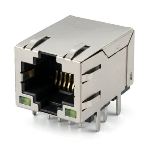
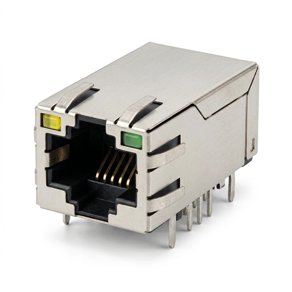
This 1×1 Single-Port RJ45 Magnetic Modular Jack (MagJack) is engineered with integrated 100Base-TX Fast Ethernet magnetics and IEEE 802.3af Power over Ethernet (PoE) capability for PSE and PD applications. Featuring a Tab-Up right-angle through-hole (DIP) configuration, it measures 16.50mm in width, 32.50mm in depth, and 13.70mm in profile height above the PCB, encased in a nickel-plated brass EMI shield with integrated Left Yellow and Right Green LED indicators.
Designed for wave-soldering through-hole PCB assembly (260°C ±5°C peak tip temperature for 5 seconds maximum), the connector utilizes a staggered multi-pin footprint featuring 16x Ø0.89mm signal and PoE pins, 4x Ø1.14mm LED pins, 2x Ø1.57mm shield grounding tabs (16.13mm span), and 2x Ø3.20mm plastic mounting holes (12.70mm span). The suggested front metal panel cutout measures 17.06mm in width by 13.88mm in height, with a dedicated 10.75mm x 21.75mm component-side keep-out zone under the connector boundary.
2026年8月14日
What is RJ45 connector? Get pinout details, Ethernet uses, and sourcing specs like plating and termination to avoid...
2024年3月12日
Introduction In today’s fast-paced and technology-driven world, the importance of reliable cable assemblies cannot be overstated. These critical...
2021年12月24日
Compare top low-MOQ custom cable assembly suppliers in China. Verify crimp tooling, sample lead times, and IPC/WHMA-A-620 quality...
2026年7月25日
Discover what connectors are essential for custom cable assemblies. From wire-to-board to circular connectors, learn to specify with...
This 1×1 Single-Port RJ45 Magnetic Modular Jack (MagJack) features an integrated 100/1000 Base-T Ethernet magnetics module engineered for...
View ProductThis 1000Base-TX Gigabit RJ45 8P8C female magnetic modular jack (MagJack) integrates internal 4-pair isolation magnetics and dual optical...
View ProductThis 100Base-TX RJ45 8P8C female magnetic modular jack (MagJack) integrates an internal 1CT:1CT isolation transformer and common-mode filtering...
View ProductThis 100Base-TX RJ45 8P8C female magnetic modular jack (MagJack) integrates internal signal isolation magnetics and dual optical LED...
View ProductProduct Document
Use this document for internal review, engineering comparison, and RFQ preparation.
We support importers, distributors, and electronics manufacturers with product matching, alternative sourcing, assembly integration, and factory-direct production coordination.