Direct answer: An RJ45 connector is the standardized 8-position, 8-contact (8P8C) modular interface used primarily for Ethernet and data transmission. The drawing reference usually points to a specific manufacturer series from Molex, TE Connectivity, JST, Amphenol, or Hirose, not a generic commodity part.
At a Glance
An RJ45 connector specifies the mating interface and contact count, not the termination style, plating stack, housing material, or retention design. Matching pin count and outline does not guarantee the connector will solder correctly, crimp onto your wire, or survive the intended mating cycles. Real-world compatibility requires verifying termination, plating, and mechanical retention against the production process.
The Starting Point: RJ45 Is an Interface Name, Not a Ready-to-Order Part Number
In many BOMs and equipment manuals, “RJ45” is used as a shorthand for a standard network jack or plug. That shorthand hides a procurement risk: it describes the interface, not the part number. The same drawing may call out a Molex modular jack series, a TE Connectivity industrial RJ45 plug, an Amphenol shielded jack with integrated magnetics, or a JST connector in equipment that uses RJ45-style mating. The generic term does not identify the exact series, plating, or retention feature.
The table below separates what the RJ45 designation controls from what it leaves open.
| Specification Layer | What “RJ45” Defines | What It Does Not Define |
|---|---|---|
| Contact layout | 8P8C positions | Contact geometry tolerances |
| Mating interface | Modular plug/jack form | Manufacturer series-specific keying or shield grounding |
| Electrical function | Ethernet/data signal path | Current rating per contact, insertion loss budget |
| Termination | Not defined | Crimp wire range or PCB soldering process |
| Material/plating | Not defined | Contact base metal, underplate, plating thickness |
| Mechanical retention | Not defined | Latch type, board locks, panel flanges, press-fit posts |
This is why incoming inspection limited to pin count, outline dimensions, and physical appearance can pass a connector that later fails on the line. The dimension check confirms you have a part that looks like the drawing; it does not confirm the process engineering underneath the housing.
What the RJ45 Name Actually Means: Jack vs Plug, T568A/B, and Branded Series
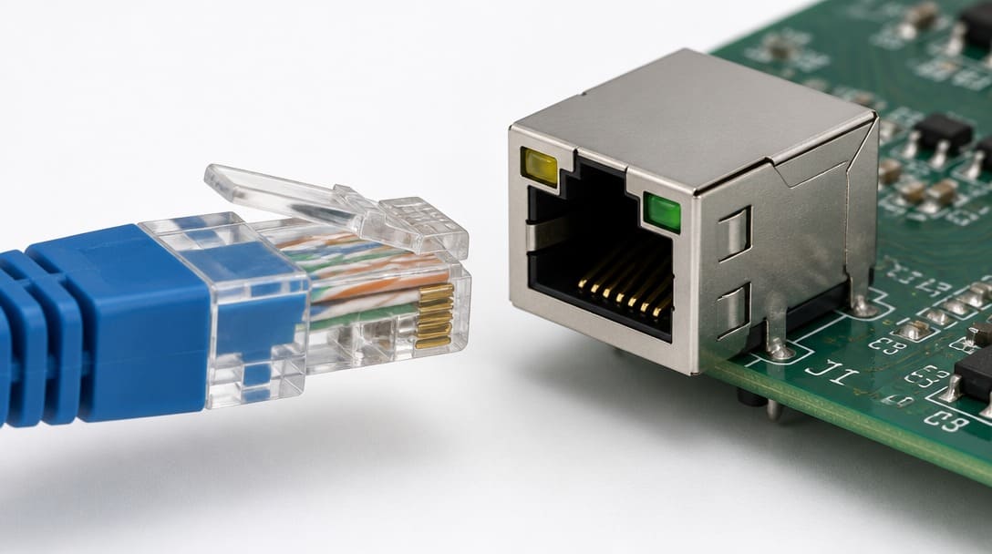
Within the RJ45 category, the jack is the female socket — typically PCB-mount or panel-mount — while the plug is the male 8P8C modular plug, usually crimped onto twisted-pair cable. Both share the same 8-position contact layout, but they are not interchangeable in procurement: a jack has solder or press-fit termination, and a plug has insulation displacement or crimp termination.
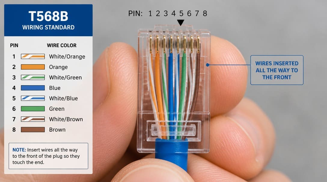
T568A and T568B are wiring pinout standards for conductor order inside the cable termination. They do not change the physical connector. A system may require one standard or the other depending on legacy cabling, patch panel design, or end-equipment pairing. The connector itself remains an 8P8C interface.
| Pin | T568A Conductor | T568B Conductor |
|---|---|---|
| 1 | White/green | White/orange |
| 2 | Green | Orange |
| 3 | White/orange | White/green |
| 4 | Blue | Blue |
| 5 | White/blue | White/blue |
| 6 | Orange | Green |
| 7 | White/brown | White/brown |
| 8 | Brown | Brown |
Drawings often carry a manufacturer-specific series code from Molex, TE Connectivity, JST, Amphenol, or Hirose while the title block simply says “RJ45.” The series code is the actual sourcing reference. The same generic interface can appear in unshielded, shielded, panel-mount, low-profile, or integrated magnetics configurations, each with different part-number-level parameters. UL and RoHS[1] references on a datasheet are compliance markers; they do not define mechanical or termination interchangeability. Two parts can both carry RoHS marking and still fail the soldering process because their plating stack differs.
Critical Parameter 1: Termination Compatibility — Crimp Wire Gauge vs PCB Soldering Window
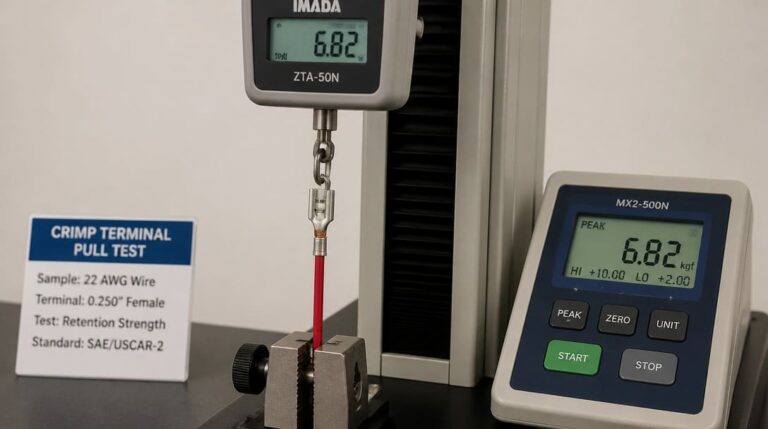
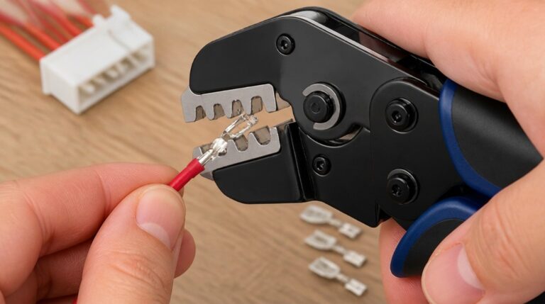
Termination is where RJ45 connectors most often hide incompatibility. For crimp-type plugs, the wire gauge range, insulation diameter, conductor material, and tooling settings determine whether the termination will hold under assembly strain. A plug that accepts the correct conductor but not the correct insulation diameter can crimp weakly even when the wire fits the contact slot. The same part number may perform differently with solid copper, stranded copper, or different insulation types.
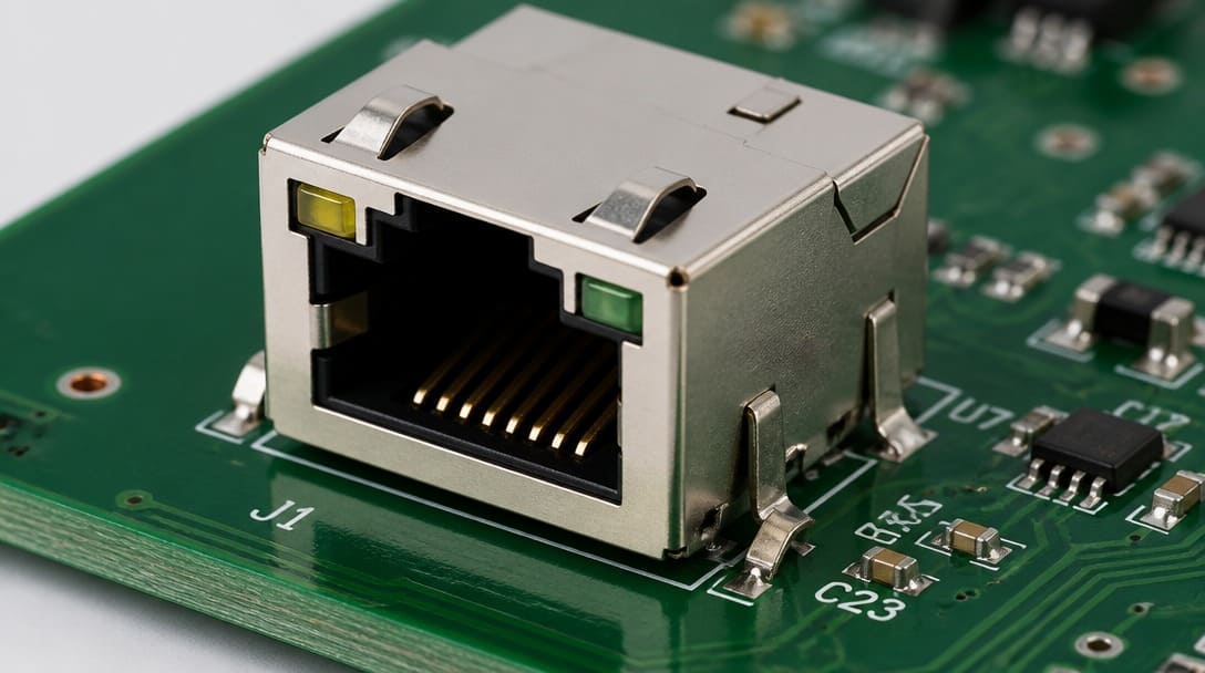
For PCB-mount RJ45 jacks, footprint dimensions alone are not enough. Through-hole and surface-mount versions may share the same 8P8C mating face, yet require different soldering process windows, pin lengths, hole sizes, and board thickness allowances. A through-hole jack may be compatible with wave soldering but not with a reflow-heavy SMT line unless specifically qualified. A surface-mount jack must match stencil aperture, paste volume, and reflow peak conditions.
We regularly see connectors that pass visual incoming inspection but fail during assembly — the termination interface or plating stack was engineered for a different process than the one running on the production line. The part looks right; the process doesn’t know it’s wrong.
| Termination Type | Key Compatibility Factors | Common Production Checks |
|---|---|---|
| Crimp plug | Wire gauge range, insulation diameter, conductor material, tooling settings | Pull force, conductor bellmouth, insulation crimp window |
| PCB-mount jack, through-hole | Hole pattern, pin length, solder wave temperature, board thickness | Solder fillet, pin protrusion, board flatness |
| PCB-mount jack, SMT | Footprint tolerance, solder paste stencil, reflow profile, coplanarity | Wetting, voiding, tombstones, connector seating |
EIA-364 defines the test family commonly used to verify termination-related mechanical and electrical performance. Buyers do not need to run every test for every order, but they should ask whether the connector was qualified against the relevant EIA-364 methods for the intended termination and stress conditions.
Critical Parameter 2: Plating Material and Thickness — What Controls Contact Reliability and Solderability
Contact plating is not cosmetic. Common RJ45 contact plating choices include gold flash, selective gold, gold-palladium-nickel, and tin. Each affects mating cycles, corrosion resistance, and field life differently. The same 8P8C outline may carry different contact plating thickness and underplate in different manufacturer series, even when the parts look identical under ordinary incoming inspection.
For PCB-mount jacks, solderability is linked to plating condition and shelf life. Solder tails that have aged, tarnished, or been stored outside the manufacturer’s packaging conditions can wet poorly even if the pins line up on the footprint. RoHS-compliant lead-free soldering raises the process temperature and changes the material compatibility requirements; a connector with a tin finish may need evaluation against the specific lead-free profile in use.
| Plating Type | Typical Application | Procurement Consideration |
|---|---|---|
| Gold flash | Low-mating data ports | Thin gold may wear quickly; verify mating cycle requirement |
| Selective gold | Contact area only | Economic balance; verify wear zone |
| Gold-palladium-nickel | Harsh or high-mating environments | Higher corrosion resistance; confirm underplate compatibility |
| Tin | Cost-sensitive, low-mating PCB tails | Solderability and shelf life; lead-free process compatibility |
EIA-364 methods for contact resistance, mating durability, and environmental exposure provide the reference frame for comparing plating performance. A buyer comparing two visually similar RJ45 connectors should ask for the plating callout and the relevant qualification summary, not just a photograph.
Critical Parameter 3: Mechanical Retention — Latches, Board Locks, and Through-Hole Anchors
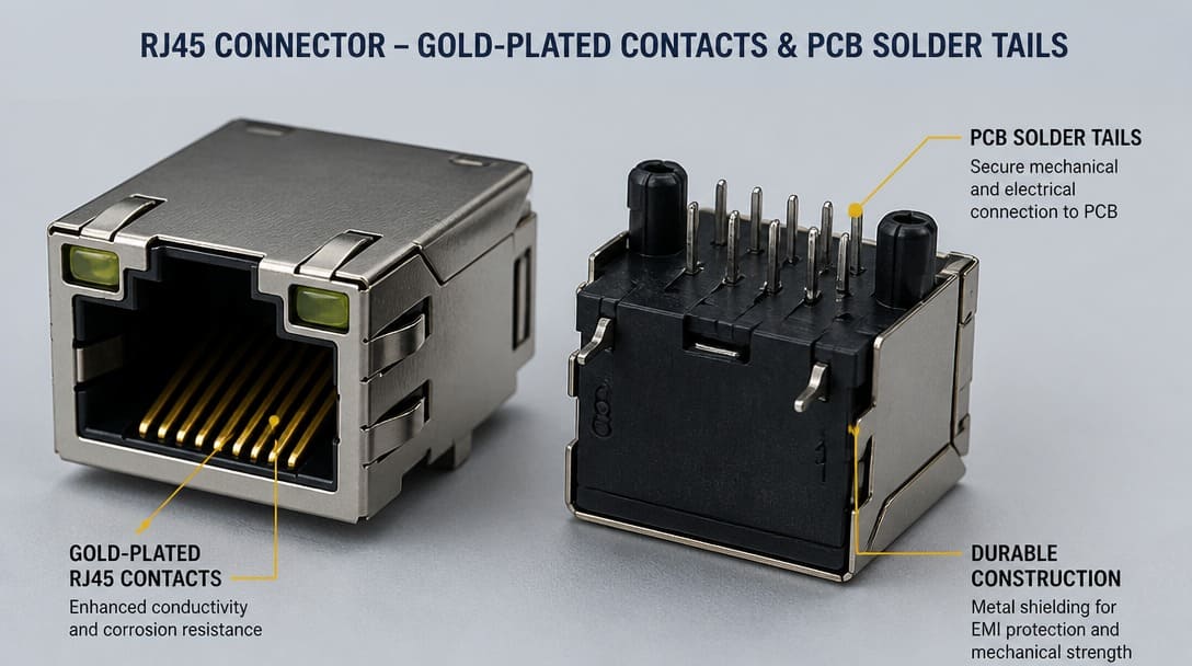
Mechanical retention changes at the part-number level even when the signal contacts stay 8P8C. Plug retention may use snagless latch guards, booted strain relief, or bare latch designs. Jack retention may depend on solder anchors, board locks, panel flanges, or press-fit posts. Two connectors with identical pinout and outline can fail in the field if latch engagement force, tab deflection, or PCB anchor type differs from the original design.
The same RJ45 footprint may be offered in no-shield, shielded, or integrated magnetics versions. Shielding changes grounding path and mechanical envelope. Integrated magnetics add height and electrical isolation requirements. Retention features such as panel flanges and press-fit posts change the mounting hole pattern and assembly process even before signal performance is considered.
| Retention Feature | Plug or Jack | Procurement Risk When Overlooked |
|---|---|---|
| Snagless latch guard | Plug | Latch protection changes cable assembly profile and handling |
| Booted strain relief | Plug | Boot geometry affects cable entry and bend radius |
| Board locks | Jack | PCB footprint may differ; missing lock reduces mechanical stability |
| Press-fit posts | Jack | Requires press-fit process, not soldering |
| Panel flange | Jack | Mounting hole pattern and grounding design must match enclosure |
Series differences from Molex, TE Connectivity, and Amphenol illustrate this clearly: a buyer can find multiple RJ45-style parts with the same 8P8C face, but distinct latch profiles, board lock positions, and shield grounding tabs. That is why part-number verification precedes any interchangeable claim.
‘Compatible’ vs ‘Interchangeable’: What Sourcing from a Drawing Often Misses
In procurement language, compatible means functionally workable within the same performance envelope. Interchangeable means a drop-in replacement with identical termination, plating, retention, and dimensions. These are not the same. A connector may be compatible with a new design but not interchangeable with the legacy part already qualified on the line.
| Sourcing Scenario | Status | What It Means for Production |
|---|---|---|
| Same series, different plating | Compatible, not fully interchangeable | Fits, but may require qualification for mating cycles or environment |
| Same footprint, different wire range | Assembly-compatible with process change | Needs new crimp tooling or validation of strip dimensions |
| Same latch, different shield grounding | Electrically compatible only in low-noise environments | May fail EMC in high-speed or industrial settings |
| Same 8P8C outline, different manufacturer series | Requires sample verification | Pin length, latch force, plating stack, and solderability may differ |
The same logic applies across manufacturer families. Molex, TE Connectivity, JST, Amphenol, and Hirose each maintain series-specific options that may share the RJ45 name but not the full part number or testing pedigree. A dimensional match may pass storage inspection and then fail at the solder wave, in the crimp tool, or under EIA-364-style mating-cycle verification. Procurement teams need to know which test failures are acceptable risks and which are immediate line-stop events.
RJ45 Connector Verification Checklist Before You Order
Before committing to an RJ45 connector order — especially for replacement or cross-reference sourcing — verify the following:
- Confirm termination method matches your assembly process. For crimp plugs, verify exact wire gauge and insulation diameter. For PCB-mount jacks, confirm soldering process, pin length, and footprint tolerance.
- Confirm plating specification meets environmental exposure, mating-cycle, and solderability requirements. Do not assume gold flash, selective gold, and tin behave identically.
- Verify key dimensions with actual samples — not just datasheet drawings. Include latch travel, tab height, pin projection, and PCB hole pattern.
- Confirm the mating interface is fully identical. Check 8P8C contact positions, keying, shield grounding, and housing entry orientation.
- Check whether RoHS and UL marks apply to the specific series and variant, not only to the general product family.
If you are matching an RJ45 connector from a BOM or equipment manual, working with a supplier that reviews termination, plating, retention, and sample fit before quoting can reduce production-line surprises. Suppliers such as EDOM Electronics support OEM buyers with requirement review, connector matching, sample coordination, production follow-up, inspection, and export-ready packaging for custom cable assemblies and wire harnesses.
From Drawing to Production: Where Connector Matching Moves Past the Datasheet
Production-coordinated connector sourcing starts with drawing and BOM review. The connector is checked against the specified series, termination method, and plating callout. Sample mating then verifies plug-to-jack engagement, latch retention, and pin alignment under real handling conditions. For cable-side RJ45 plugs, termination trial on actual wire stock confirms crimp quality before volume cutting and stripping begins. For PCB-mount jacks, the sample is compared against the stencil or footprint, and solderability is reviewed before the reflow or wave process is locked.
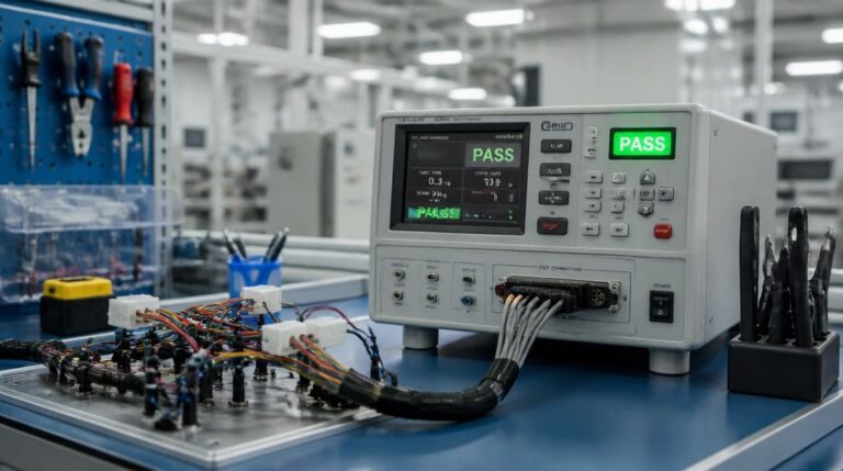
Continuity and appearance inspection complete the verification loop. Continuity identifies intermittent contacts or miswired T568A/B conductor order. Appearance inspection catches housing damage, latch defects, plating discoloration, and improper shield seating. When connectors are part of custom cable assemblies or larger wire harnesses, export packaging must protect the latch feature and solder tails through transit; practices such as those covered in quality inspection and export packaging reduce the chance that a good connector arrives damaged.
OEM buyers and distributors benefit from resolving termination compatibility, plating, and mechanical retention before committing to volume orders. That is the point where connector matching moves past a datasheet comparison and becomes production risk control.
For a broader overview of connector categories and how they fit into an electronic assembly, see the pillar guide What Is a Connector.
Frequently Asked Questions
Is RJ45 the same as 8P8C?
RJ45 is the common name for the 8-position, 8-contact modular interface used in Ethernet and data transmission. Technically, 8P8C describes the contact arrangement; RJ45 is the application-oriented name. The two are often used interchangeably, but a sourcing document should still call out the manufacturer series because 8P8C does not define termination, plating, or retention.
What is the difference between T568A and T568B pinout?
T568A and T568B are two wiring standards that define conductor order inside the RJ45 plug. They use different pair ordering but the same physical connector. The choice depends on existing cabling, patch panel configuration, or customer specification. A mismatch can cause a correct 8P8C connector to be wired incorrectly for the intended network.
Can I use any RJ45 connector with the same pin count as a replacement?
No. Pin count and outline are only the visible layer of compatibility. Crimp plug wire gauge range, insulation diameter, tooling settings, PCB-mount soldering window, plating stack, latch design, board locks, and shield grounding can all differ between manufacturer series. A part that looks identical may fail during assembly or in the field.
What does RoHS compliance mean for RJ45 connectors?
RoHS restricts certain hazardous substances in the connector materials. For RJ45 connectors, RoHS compliance may require lead-free compatible plating and termination finishes. This affects soldering process temperature and material compatibility, not just environmental certification. The RoHS mark should be verified for the specific series and variant.
What should I check before ordering RJ45 connectors from a new supplier?
Confirm termination method against your assembly process, plating specification against environmental and mating-cycle requirements, key dimensions on actual samples, full mating interface details including keying and shield grounding, and whether RoHS and UL references apply to the exact series. Sample mating and termination trial before volume order are the most direct way to reduce line-stop risk.
Key Takeaways
- RJ45 is an interface name for an 8P8C modular connector; it does not define termination, plating, retention, or exact part number.
- Jack and plug versions have different termination and mounting requirements, even though they share the same contact layout.
- T568A and T568B are wiring pinout standards for conductor order, not physical connector differences.
- Termination compatibility, plating material and thickness, and mechanical retention are the hidden parameters that determine whether an RJ45 connector will work on the production line.
- Compatible is not the same as interchangeable; drop-in replacement requires identical termination, plating, retention, and dimensions.
- Sample mating, termination trial, continuity inspection, and appearance inspection reduce the gap between drawing-based sourcing and production reality.
For application-specific support with connector selection, cross-reference review, and production coordination, visit electronic connector solutions.