2026年8月14日
What Is an RJ45 Connector? Understanding RJ45 Pinout and Uses
What is RJ45 connector? Get pinout details, Ethernet uses, and sourcing specs like plating and termination to avoid...

Rapid Prototyping in 3-5 Days
B2B Electronic Connection Solution
Factory-backed connector sourcing and electric connection support for OEMs, distributors and electronic equipment manufacturers.
OEM Ready
Factory Supply
Fast Quote
Product Specifications
Key parameters for OEM, distributor and engineering evaluation.
Detailed Product Information
Structured parameters, material notes, application context and frequently asked questions for engineering and procurement evaluation.
Drop-in Replacement: This part is a direct, pin-compatible substitute for the competitor part number listed above. No design modification required.
| Material | Value / Description |
|---|---|
| Housing Material | Thermoplastic, PBT, UL 94V-0, Black |
| Insert Material | Thermoplastic, PBT, UL 94V-0, Black |
| Coil Base Material | Phenolic, PBT, UL 94V-0, Black |
| Contact Terminal Material | Phosphor Bronze |
| Contact Area Plating | 6µ" Gold Plating over 50µ" Nickel Underplate |
| Solder Area Plating | 100µ" Tin Plating over 50µ" Nickel Underplate |
| Coil Terminal | Copper Alloy (T = 0.40 x 0.40 mm Thickness) |
| Metal Shell Material & Plating | Copper Alloy, 30µ" Nickel Plated Overall |
| Characteristic | Value |
|---|---|
| Inductance (OCL) | 350 µH Min. with 8 mA DC Bias Current |
| Dielectric Isolation | 1500 Vrms Min. (per IEEE 802.3 requirement) |
| LED Wavelength | Green: 568 nm; Yellow: 585 nm |
| LED Forward Voltage (Min/Max) | 1.8 V / 2.8 V @ 20 mA Forward Current |
| Operating Temperature Range | 0°C to +70°C |
| Storage Temperature Range | -40°C to +85°C |
| General Dimensional Tolerances | 0 Place: ±0.50 mm; 1 Place: ±0.25 mm (±0.015"); 2 Place: ±0.15 mm (±0.01"); Angular: ±3° |
10/100/1000Base-TX Gigabit industrial Ethernet switches, routers, and enterprise gateways
Embedded Single Board Computers (SBC), IPCs, and edge AI computing nodes
Network Video Recorders (NVRs) and high-definition IP surveillance hardware
Industrial automation controllers, PLCs, and high-speed machine vision systems
Telecom base station interfaces and commercial network appliances
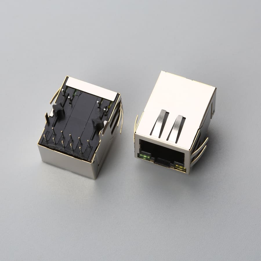
This 1000Base-TX Gigabit RJ45 8P8C female magnetic modular jack (MagJack) integrates internal 4-pair isolation magnetics and dual optical LED indicators (Left Green/Yellow, Right Yellow) into a single 1×1 port assembly. Featuring a tab-down latch orientation and right-angle through-hole DIP mounting, it delivers IEEE 802.3 compliant 10/100/1000 Mbps signal conditioning, 1500Vrms galvanic isolation, and active port diagnostics for Gigabit industrial switches, edge servers, and embedded computing boards.
Designed for through-hole component-side mounting on standard FR-4 circuit boards. The Gigabit signal footprint incorporates a 10-pin staggered array (P1–P10) to accommodate all four differential pairs and center taps, paired with 4 through-hole terminals for the integrated LEDs (P11–P14). Physical retention and 360-degree EMI grounding are reinforced by dual plastic locating posts and dual shield solder tabs spaced 15.75mm apart.
2026年8月14日
What is RJ45 connector? Get pinout details, Ethernet uses, and sourcing specs like plating and termination to avoid...
2024年3月12日
Introduction In today’s fast-paced and technology-driven world, the importance of reliable cable assemblies cannot be overstated. These critical...
2026年7月25日
Discover what connectors are essential for custom cable assemblies. From wire-to-board to circular connectors, learn to specify with...
2026年7月31日
What is a cable assembly? Learn the engineered definition per IPC/WHMA-A-620, key components, and applications. Avoid mismatched specs—read...
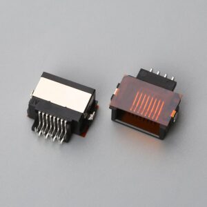
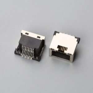
This mid-mount sinking RJ45 8P8C female modular jack features a half-shield structure (semi-shielded) with a 5.50mm sinking depth...
View ProductThis mid-mount sinking RJ45 8P8C female modular jack integrates dual LED indicators (Orange Left / Green Right) with...
View ProductThis mid-mount sinking RJ45 8P8C female modular jack integrates dual LED indicators (Left Yellow / Right Green) with...
View ProductThis mid-mount sinking RJ45 8P8C female modular jack combines surface-mount (SMT) straight-pin contacts with integrated dual LED indicators...
View ProductProduct Document
Use this document for internal review, engineering comparison, and RFQ preparation.
We support importers, distributors, and electronics manufacturers with product matching, alternative sourcing, assembly integration, and factory-direct production coordination.