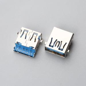
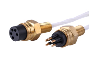
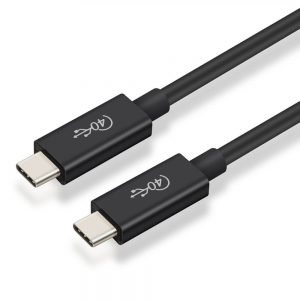
If you’ve ever stared at a bill of materials or an engineering drawing and asked yourself, “What exactly is a cable assembly, and why can’t I just use a few wires and connectors?” — you’re not alone. OEM buyers, procurement managers, and even seasoned engineers encounter this question at the starting line of countless projects. The term sounds simple, but misunderstanding it has consequences: mismatched specifications, failed field deployments, and expensive reorders that could have been avoided with one clear definition.
Direct Answer: A cable assembly is a predetermined grouping of cables, connectors, and protective components — terminated and ready to install — built to meet the acceptance criteria defined in IPC/WHMA-A-620[1]. It is an engineered unit designed for a specific application, environment, and mechanical stress profile, not merely a collection of wires with connectors attached.
What Is a Cable Assembly?
On the factory floor, a cable assembly is treated as a finished subassembly — a sealed, tested, and often overmolded interconnect solution that moves power or signals between two points in a system. Every element, from the conductor strand count to the durometer of the overmold material, is selected with intention. The assembly is built to a drawing that specifies lengths, connector orientations, label placement, and test requirements before it ever reaches the production bench.
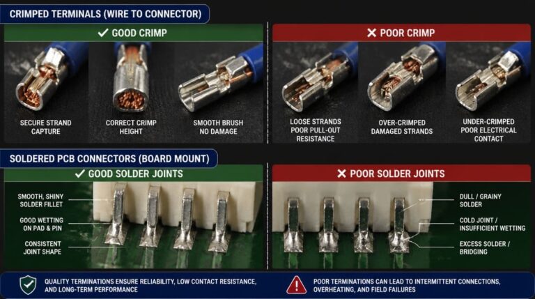
The distinction matters because procurement teams frequently encounter situations where a colleague requests “just a cable” for an outdoor enclosure, only to discover months later that the unit needed a UV-stabilized jacket, a shielded twisted pair for noise rejection, and an IP67-rated circular connector to survive in the field. What began as a simple purchase order becomes a recall or a field retrofit — all because the definition wasn’t pinned down at the start. IPC/WHMA-A-620 provides the common language: it defines workmanship acceptance classes that govern crimp quality, soldering, connector fit, and strain relief, giving both buyer and manufacturer a measurable standard to reference.
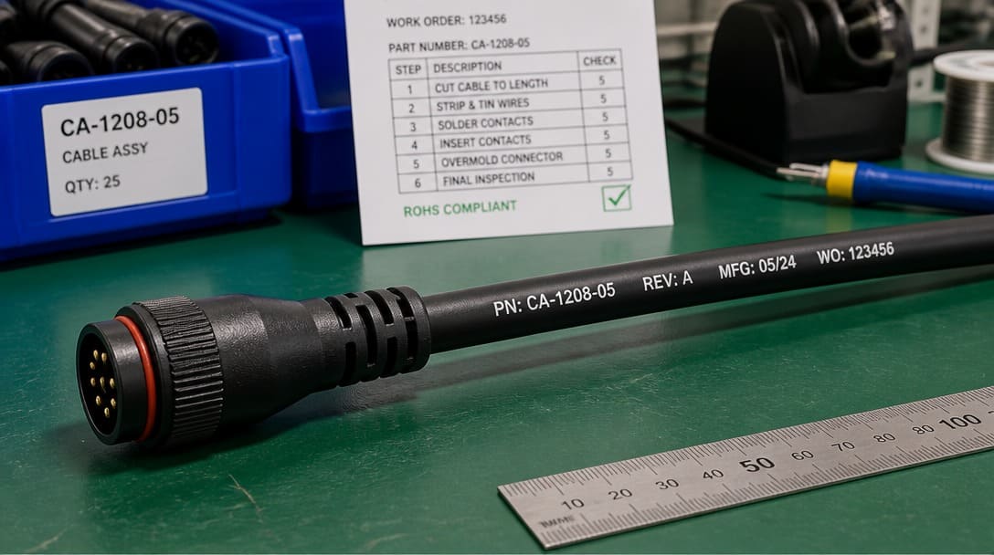
Core Components: Conductors and Insulation
The conductor is the foundation of any cable assembly, and the choice between stranded and solid wire is dictated by the mechanical environment. Stranded conductors — composed of multiple thin copper filaments twisted together — tolerate repeated flexing and vibration without fracturing, making them mandatory in robotics, automotive engine compartments, and any application where the cable will move during operation. Solid conductors offer lower cost and simpler termination but are suited only to static installations inside enclosures. AWG (American Wire Gauge) selection balances current-carrying capacity against physical space and flexibility requirements — a decision that must be made before the first connector is specified.
Insulation material selection is equally consequential. PVC (polyvinyl chloride) remains the cost-effective workhorse for indoor appliances and general-purpose signal wiring, offering adequate dielectric strength at moderate temperatures. XLPE (cross-linked polyethylene) steps up in temperature resistance and chemical tolerance, commonly found in automotive under-hood applications where exposure to oil, fuel vapor, and heat cycling is routine. Silicone insulation delivers exceptional flexibility across a wide temperature range, ideal for medical device leads and laboratory equipment that must remain pliable in cold sterilization environments. PTFE (polytetrafluoroethylene) occupies the high-performance tier — its temperature range and low-friction surface suit aerospace and defense applications where outgassing and dielectric stability are non-negotiable. Selecting the wrong insulation material early in a project leads to jacket cracking, dielectric breakdown, or insulation melt-through long before the equipment’s expected service life ends. UL standards, particularly those governing Appliance Wiring Material (AWM), provide the reference framework for verifying that insulation choices match the end application’s thermal and voltage requirements.
Shielding and Jacketing
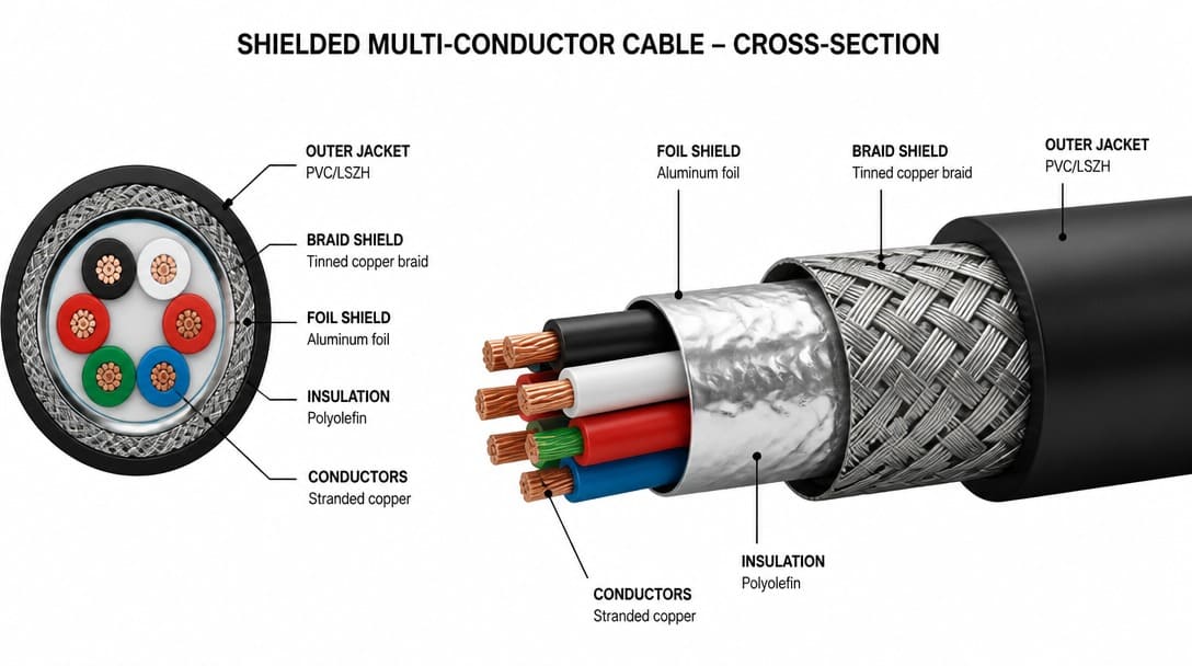
Once the conductor and insulation are defined, the next layer of engineering addresses electromagnetic interference and physical protection. Shielding comes in three primary configurations: foil tape, braided wire, and combination foil-plus-braid. Foil shields, typically aluminum-backed polyester tape with a drain wire, excel at blocking high-frequency noise and add minimal weight — a practical choice for compact sensor cables and data links inside metal enclosures. Braided shields use woven copper strands to create a conductive barrier around the inner conductors, providing superior low-frequency noise rejection and robust mechanical durability, which matters in industrial environments where cables are repeatedly flexed or routed near motor drives. Combination shielding layers a foil wrap beneath a braid, delivering broadband EMI protection for critical signal paths such as encoder feedback cables in CNC machinery or medical imaging interconnects.
The outer jacket is the assembly’s first line of defense against abrasion, oil, UV radiation, moisture, and temperature extremes. Polyurethane jackets resist abrasion and cut-through in robotic dress packs; CPE (chlorinated polyethylene) offers oil resistance for hydraulic equipment; TPE (thermoplastic elastomer) balances flexibility with environmental sealing in outdoor telecom installations. A frequently overlooked principle in cable assembly design is the 360-degree shield termination rule: the shield must make electrical contact around the entire circumference of the connector backshell — not just a single drain wire pigtail — to prevent EMI leakage at the termination point. When this rule is violated, the resulting “slot antenna” effect can couple noise into signal lines, producing intermittent data errors that are notoriously difficult to diagnose in the field.
Connectors and Overmolding
Connector selection transforms the cable assembly from a generic wire bundle into an application-specific interconnect. Common families include D-subminiature connectors for legacy industrial I/O and data ports, circular connectors (M12, M8, and larger M23 variants) for sensor and actuator wiring in factory automation, rectangular connectors for multi-circuit power distribution, and modular connectors such as RJ45 for Ethernet or USB for data peripherals. Each family presents a matrix of choices: pin count, contact plating, locking mechanism, keying, and ingress protection rating. An IP67-rated circular connector, for instance, requires a gasket or O-ring seal at the mating interface and a compression-fit cable gland or overmolded strain relief to maintain the environmental seal at the cable entry.
Overmolding is the process that sets a true cable assembly apart from a connector screwed onto a cable. Hot-melt PVC or thermoplastic elastomer is injected around the connector termination under controlled pressure and temperature, creating a monolithic bond between the connector body, the cable jacket, and the internal solder or crimp joints. This single-piece construction eliminates the crevices and mechanical joints where moisture can penetrate and where strain can concentrate, distributing bending forces along a graduated flex zone rather than at the rigid solder cup boundary. Assembly-style connectors with threaded or snap-on backshells remain useful for field-repairable connections and low-volume prototyping, but for production deployments exposed to vibration, washdown, or outdoor weather, overmolding is the standard. Achieving a reliable overmold requires precise tooling that matches the cable jacket diameter and material chemistry to ensure a hermetic bond — a process detail that separates experienced cable assembly manufacturers from general wire shops. When evaluating environmental protection strategies, comparing overmolding vs potting vs braided sleeving helps determine the right balance between ingress sealing, mechanical strain relief, and cost.
Cable Assembly vs. Wire Harness
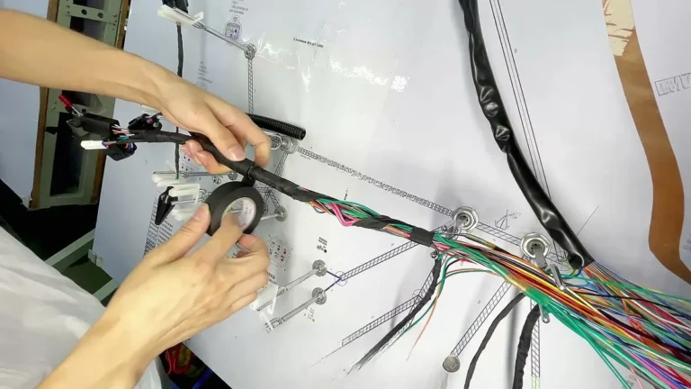
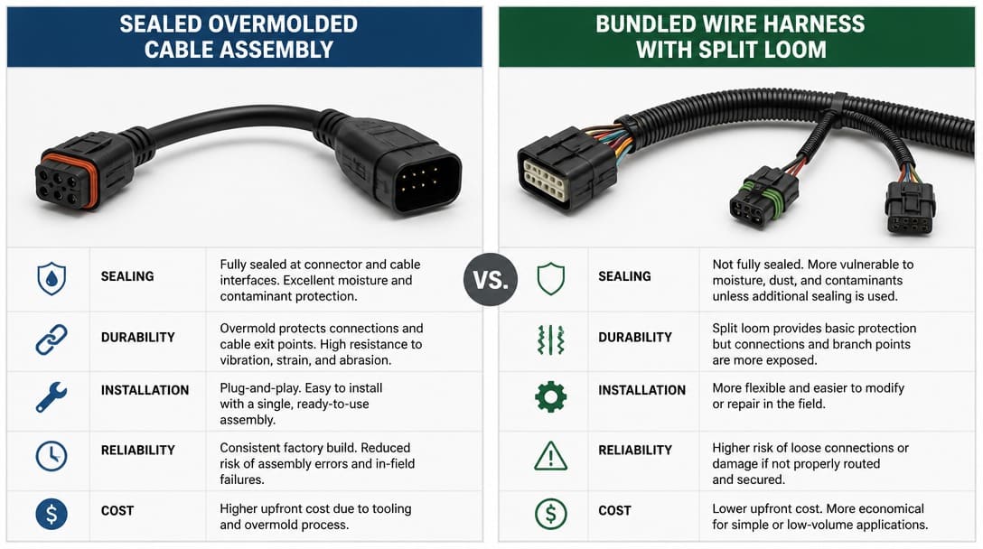
The terms “cable assembly” and “wire harness” are frequently used interchangeably in casual conversation, but they describe two distinct products with different engineering, manufacturing, and application requirements. A wire harness is a bundled arrangement of individual wires — typically bound with tape, split loom, braided sleeving, or cable ties — that routes power and signals among multiple connection points within a single chassis or enclosure. It is built to a wiring schematic, organized to simplify installation on an assembly line, and designed for a protected interior environment. A cable assembly, by contrast, is a sealed, shielded, ready-to-install interconnect built to withstand external stresses: weather, EMI, mechanical flex, and chemical exposure.
| Parameter | Cable Assembly | Wire Harness |
|---|---|---|
| Definition | Engineered grouping of cables and connectors, sealed and shielded, built for a specific external environment | Organized bundle of individual wires routed to multiple endpoints, built for internal chassis wiring |
| Environment | Exposed to weather, vibration, EMI, chemicals, UV, or operator handling | Protected interior of a cabinet, enclosure, or vehicle cabin |
| Protection | Overmolded connectors, sealed jackets, continuous shielding, strain relief | Tape, split loom, conduit, or braided sleeving for organization |
| Testing | Continuity, hipot, insulation resistance, crimp tensile, and environmental seal tests per IPC/WHMA-A-620 | Continuity and point-to-point verification per wiring schematic |
| Cost Profile | Higher per-unit cost due to materials, tooling, and testing | Lower per-unit cost for simple routing and bundling |
| Typical Use | Outdoor sensors, engine compartments, medical imaging, industrial robot arms, telecom jumpers | Control panels, appliance wiring, vehicle dashboards, server rack internal cabling |
A procurement assistant who sees “cable assembly” on a BOM for an outdoor environmental sensor but orders a simple wire harness with loose connectors will face a predictable outcome: water ingress, corrosion, and premature failure. For outdoor applications, it’s essential to specify a waterproof cable assembly designed to prevent moisture intrusion. When internal wiring requires branch taps or wire extensions, evaluating butt splice vs parallel splice crimp terminals ensures inline tensile pull points and pigtails meet mechanical load paths. When sizing mechanical bundle protection between chassis runs and connector exits, understanding braided sleeving vs convoluted tubing capacity prevents backshell pinch and harness split cracking before issuing production drawings.
Industry Standards and Compliance
Professional cable assembly manufacturing operates within a framework of industry standards that define acceptable workmanship, material quality, and environmental responsibility. IPC/WHMA-A-620 is the primary acceptance standard, and compliance is key to consistent cable assembly quality.
IPC J-STD-001 complements this standard by specifying requirements for soldered electrical and electronic assemblies, directly relevant when cable assembly connectors are soldered rather than crimped. UL certification addresses safety at the system level — a UL-listed cable assembly has undergone testing for fire resistance, dielectric withstand, and mechanical integrity, a requirement commonly referenced by North American OEMs for equipment that will bear a UL mark. On the environmental compliance side, RoHS (Restriction of Hazardous Substances) restricts the use of lead, mercury, cadmium, and other substances in conductors, insulation, and connector plating, while REACH (Registration, Evaluation, Authorisation, and Restriction of Chemicals) imposes broader chemical safety obligations for products entering the European Union. A supplier working with export-oriented OEM buyers should provide RoHS and REACH compliance documentation as a standard part of the quotation package, not as an afterthought. The combination of these standards — process quality from IPC, safety from UL, and material compliance from RoHS/REACH — forms the baseline that separates documented, repeatable cable assembly production from ad-hoc wiring.
Typical Applications Across Industries
Cable assemblies appear wherever a subsystem must exchange power or data with another subsystem across a boundary that imposes environmental, mechanical, or electromagnetic stress. In automotive applications, engine sensor cables, battery management system interconnects, and infotainment harness-to-module jumpers all demand vibration resistance, chemical tolerance, and sealed connectors rated for engine-bay temperatures. Medical device assemblies — patient monitoring leads, ultrasound transducer cables, and electrosurgical instrument cords — impose additional requirements for biocompatible jacket materials, cleanable surfaces, and overmolded strain reliefs that withstand repeated disinfection cycles without degrading.
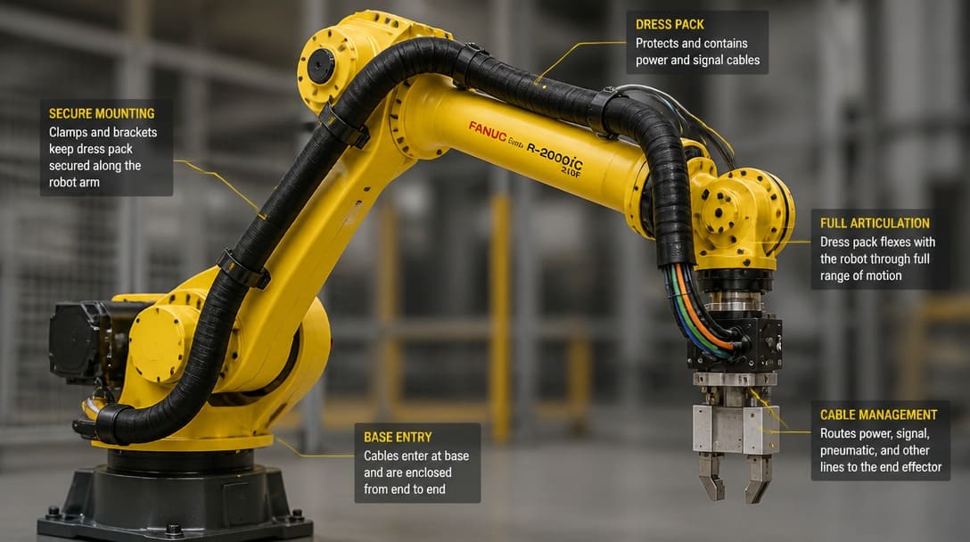
Industrial automation deploys cable assemblies in robot dress packs, CNC spindle motor cables, and distributed I/O sensor networks where flex-rated construction, oil-resistant jacketing, and 360-degree shielding against variable-frequency drive noise are baseline expectations. Telecom infrastructure relies on precision RF cable assemblies for base station jumpers and data center interconnects, where low return loss and weatherproofed connector interfaces ensure signal integrity across years of outdoor exposure. Aerospace applications push material requirements to the extreme: lightweight, high-temperature dielectric materials, full lot traceability documentation, and testing protocols that verify every assembly against its unique acceptance test procedure before shipment. Each industry context shapes the assembly’s bill of materials in a unique way — there is no universal “standard cable” that serves all markets equally.
Do I Need a Cable Assembly?
Deciding between a cable assembly and a simpler interconnect approach should be driven by the operating environment, not by initial unit cost alone. The following checklist identifies the conditions under which a cable assembly is the appropriate specification:
- Will the connection be exposed to moisture, dust, or outdoor weather? If yes, the sealed construction and IP-rated connector interface of a cable assembly are required.
- Is there relative movement, vibration, or repeated flexing in the application? Stranded conductors, overmolded strain relief, and flex-rated jacket materials prevent conductor fatigue at termination points.
- Does the connection carry high-frequency signals susceptible to electromagnetic interference? Shielded construction with proper 360-degree termination preserves signal integrity in noisy environments.
- Must the assembly pass installed-system safety or performance tests? Cable assemblies built to IPC/WHMA-A-620 acceptance criteria provide the documentation and consistency that regulatory testing demands.
- Will operators or maintenance personnel handle the connector during normal use? Overmolded connectors with integrated strain relief withstand pulling, yanking, and repeated mating cycles that would damage an unshielded wire bundle.
If the answers to all five questions are “no” — the connection lives entirely inside a protected enclosure, experiences no movement, and carries only low-frequency signals in an electrically quiet environment — a wire harness may be the more cost-effective choice. But when any single risk factor is present, specifying a cable assembly at the design stage costs far less than diagnosing and replacing failed wiring after equipment has been deployed. A pragmatic rule of thumb: when in doubt, specify the cable assembly and validate the specification with the manufacturer before committing to production quantities.
What Goes Wrong in the Field When the Wrong Choice Is Made
I once walked through a startup’s field installation yard and saw a row of outdoor gateway enclosures — each one connected to its antenna with a flat ribbon cable, unshielded, with no overmolding, no UV protection, just a simple IDC connector at each end. It looked like something pulled from a development breadboard, not a product destined for rooftop mounting. Inside six months, moisture had wicked along the individual conductors from the exposed connector face, capillary action drawing water directly into the PCB header pins inside the sealed enclosure. The corrosion spread across the board, and the entire deployment was scrapped. It wasn’t a component defect — it was a specification error that a proper cable assembly with a sealed overmolded connector would have prevented from day one.
In a different industry, a medical device engineering team attempted to reduce bill-of-materials cost on an electrocardiogram acquisition module by substituting a cable assembly that lacked continuous shield termination. The drain wire was soldered at only one end, leaving a floating shield segment that acted as an antenna for 50 Hz mains noise. The resulting baseline wander and periodic artifact in the ECG trace consumed months of troubleshooting and delayed regulatory submission. The root cause traced back to a single decision made during sourcing: treating the cable as a commodity part rather than an engineered component whose electrical behavior was inseparable from the system’s clinical performance. These failures are not rare exceptions — they are the predictable outcome of underestimating what a cable assembly is and why its design details exist.
Starting the Conversation with a Manufacturer
Initiating a cable assembly project with a manufacturer becomes significantly more efficient when the buyer arrives prepared with a defined set of inputs. A dimensioned drawing or sketch — even a rough one with overall length, connector orientation, and label placement noted — anchors the conversation in measurable requirements. The target application environment should be described in specific terms: temperature range, exposure to fluids or UV, vibration profile, and whether the assembly will be handled by operators or installed permanently. Electrical specifications — operating voltage, current per conductor, signal type and frequency — allow the manufacturer to validate conductor gauge, insulation rating, and shielding configuration against the application’s actual demands.
Mechanical constraints matter equally: minimum bend radius, clearance for connector mating and unmating, and any routing path that the assembly must follow within the equipment. Required certifications should be stated upfront — UL listing, IPC/WHMA-A-620 class level, RoHS and REACH compliance — so the quotation reflects the correct testing and documentation scope from the start. A supplier with structured inquiry handling, such as EDOM Electronics, will walk through drawing review, connector matching, and sample coordination before production begins, and will include process verification steps — crimp quality checks, continuity testing, appearance inspection — along with export-ready packaging and quality inspection documentation as part of the standard workflow. Early supplier involvement catches misinterpretations before tooling is committed, reducing the risk that the finished assembly meets the drawing but misses the application. For site contractors and field engineering teams evaluating direct manufacturing vs. catalog stock, our guide on where to buy pre-terminated cable assemblies for installers details the acceptance testing and RFQ screening required to avoid field failure. If you are preparing an RFQ or vetting manufacturing partners, review our complete cable assembly specification checklist for China sourcing to lock critical parameters before requesting quotes.
Frequently Asked Questions
What is the difference between a cable and a cable assembly?
A cable is the raw multi-conductor or coaxial transmission line — the insulated wires with optional shielding and jacket — before connectors are attached. A cable assembly is the complete, tested, ready-to-install product that includes terminated connectors, overmolding or backshells, strain relief, and any required labeling or protective sleeving.
How do I know if I need overmolding on my cable assembly?
Overmolding is recommended when the assembly will be exposed to moisture, frequent handling, vibration, or pulling forces at the connector. It provides a sealed, monolithic strain relief that distributes mechanical stress away from the internal solder or crimp joints. If the application is entirely internal to a protected enclosure with minimal mechanical stress, an assembly-style backshell may be sufficient.
What standards should a cable assembly manufacturer follow?
IPC/WHMA-A-620 is the primary acceptance standard for cable and wire harness assemblies, defining workmanship criteria for crimping, soldering, and connector installation. IPC J-STD-001 governs soldered connections when applicable. UL certification verifies safety compliance for the complete assembly, and RoHS/REACH compliance ensures material-level environmental conformity for markets requiring it.
Can a cable assembly be repaired in the field?
Field repair of an overmolded cable assembly is generally not recommended because the molded strain relief and environmental seal cannot be recreated outside the factory tooling. Assembly-style connectors with threaded backshells are more amenable to field repair, but any repair should be followed by continuity and insulation resistance testing to verify integrity before returning the equipment to service.
What information does a manufacturer need to quote a custom cable assembly?
A complete RFQ package includes a drawing or sketch with dimensions and connector types, the target application environment, electrical specifications (voltage, current, signal type), mechanical constraints, and any regulatory certifications. To ensure completeness, refer to the top 10 electrical specifications for cable assembly and wiring harness.
Key Takeaways
- A cable assembly is an engineered, sealed, and tested interconnect built to IPC/WHMA-A-620 acceptance criteria — not a simple collection of wires and connectors — and its design choices directly determine field reliability.
- Conductor type, insulation material, shielding configuration, and jacketing are interdependent decisions driven by the application’s electrical, mechanical, and environmental requirements.
- The distinction between a cable assembly and a wire harness hinges on environmental exposure, protection level, and testing — confusing the two leads to field failures that are far more expensive than the upfront cost difference.
- Industry standards including IPC/WHMA-A-620, IPC J-STD-001, UL, RoHS, and REACH provide the framework for verifying workmanship quality, safety compliance, and material conformity across production batches.
- Engaging a knowledgeable manufacturer early in the specification process — with a drawing, application details, and certification requirements in hand — reduces lead time, prevents misinterpretation, and ensures the delivered assembly matches the end-use environment.
For buyers evaluating cable assembly sourcing options, understanding these fundamentals transforms the specification process from a reactive purchase into an informed engineering decision. Explore custom cable assembly solutions built to application-specific requirements with documented quality control and export-ready packaging.