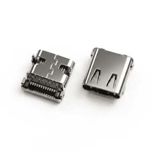
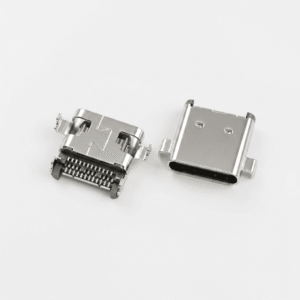
Terminal plating fretting corrosion is a contact degradation mechanism in which micro-motion between mating connector surfaces(see What Is a Connector? A Practical Overview for OEM Buyers) generates non-conductive wear debris and oxide accumulation inside the wipe track, causing intermittent opens and elevated contact resistance even when terminal bodies appear visually clean.
A field return often starts the same way: an intermittent open appears after months of thermal and vibration cycling, the pins look visually intact under standard inspection, and continuity testing cannot reproduce the failure. In another project, a new design stalls because tin and gold contact systems are being mixed across a separable connector interface. Both situations share the same hidden driver: relative micro-motion between contact surfaces generating non-conductive debris inside a wipe track that looks clean at low magnification.
Diagnostic Fork: Plating-Wear Fretting vs. Tin-Oxide Debris, Galvanic Mismatch, and Environmental Corrosion
Before changing a plating specification or releasing a corrective action, the failure path must be separated. Fretting corrosion is defined by micro-motion between mating connector surfaces. That motion generates wear debris and oxide accumulation inside the contact wipe track, even when the connector housing remains fully latched and the terminal body shows no gross damage. Four failure paths are commonly confused at the field-return bench:
- Wear-through fretting: plating is mechanically worn away until the base material or nickel underplate is exposed inside the wipe track.
- Tin-oxide debris: tin plating remains present, but cyclic micro-motion produces an insulating tin-oxide layer and debris accumulation.
- Galvanic mismatch: tin and gold are mixed across a separable interface, producing oxide transfer and electrochemical interaction in the presence of moisture.
- Environmental corrosion: external humidity, salt spray, or industrial gases attack the terminal surface, often after plating breach or underplate porosity.
Use the following decision tool to separate these mechanisms before selecting a fix.
| Failure path | Wipe-track appearance | Plating thickness / underplate condition | Mating metal pair | Dominant environment | Next diagnostic action |
|---|---|---|---|---|---|
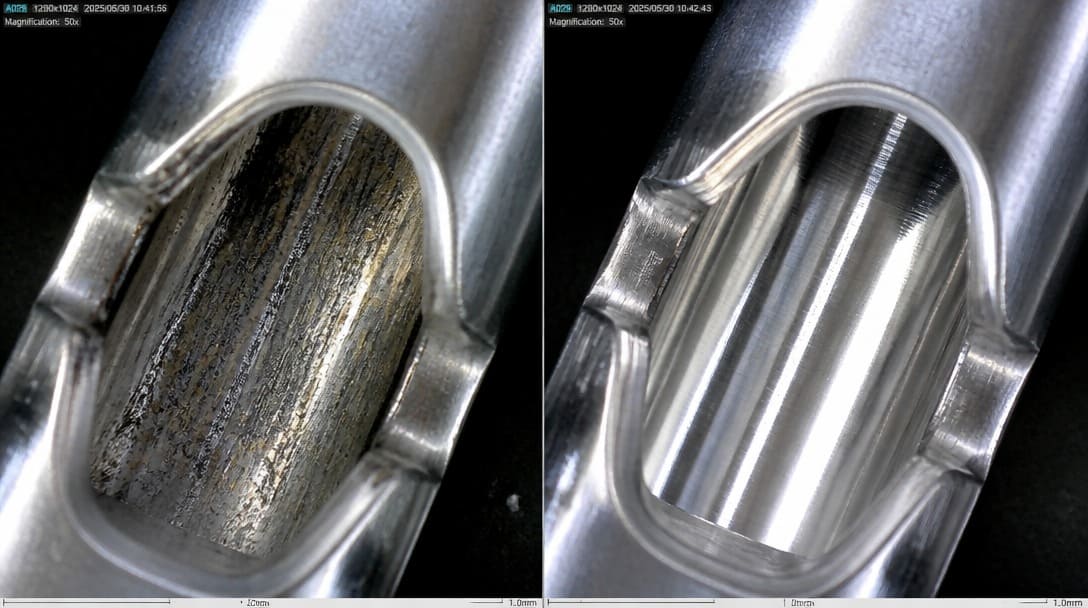
| Wear-through fretting | Visible base metal or nickel underplate exposed in the track | Plating depleted below minimum in the contact zone | Same-metal pair or tin-to-tin | High vibration, thermal expansion mismatch | Microsection and XRF mapping across the wipe track |
| Tin-oxide debris | Dull gray or black powdery accumulation inside the track | Tin still present, but oxide layer is thick | Tin-to-tin or tin against gold | Humid, sealed, or micro-motion-prone harness | Low-level contact resistance plus surface analysis; review lubrication |
| Galvanic mismatch | Gold side may appear clean; tin side shows oxide transfer | Gold over nickel intact, tin mating surface degraded | Tin-to-gold separable interface | Humidity or condensation present | Mixed-metal design review; eliminate uncontrolled tin-to-gold pair |
| Environmental corrosion | Corrosion product, sulfidation, or spot discoloration | Plating breached or underplate porosity present | Any mating pair | Salt spray, industrial gas, high humidity | Environmental testing plus cross-section and material verification |
Plating System Selection for the Mating Cycle and Vibration Profile
Plating selection is not simply a cost decision. It must match the expected mating cycle count, normal force capability, and vibration profile of the application. The table below compares the most common terminal plating systems for separable connectors.
| Plating system | Mating cycle tolerance | Typical normal force requirement | Vibration tolerance | Contact resistance stability | Primary cost driver |
|---|---|---|---|---|---|
| Tin plating | Lower mating cycles (< 50 cycles); best for non-separable or stable harnesses | High normal force required (typically ≥ 1.5–2.0 N) to mechanically rupture hard tin oxide | Limited under sustained micro-motion (amplitudes > 5–10 µm); sensitive to fretting debris | Higher initial resistance; risk of rapid excursion over thermal/vibration cycling | Low material cost, but restricted operating window |
| Selective gold over nickel | High mating cycle tolerance (100–500+ cycles depending on Au thickness) | Operates reliably at low normal force (typically 0.3–0.5 N) | Stable under vibration when terminal retention is locked | Low and exceptionally stable contact resistance | Higher plating cost, controlled to wipe track only |
| Duplex gold-plus-tin | High mating cycles in the gold wipe zone; tin on termination tails | Gold zone operates at 0.3–0.5 N; crimp/solder tail remains non-separable | Dependent on a strictly defined transition line preventing gold-tin contact overlap | Stable in the separable contact zone; tail remains outside active wipe path | Moderate cost with selective plating tooling control |
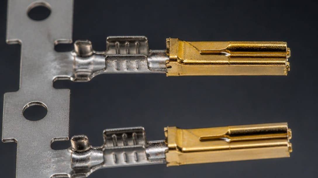
Tin plating requires high normal force because tin oxide is hard and must be mechanically ruptured at every engagement. That makes tin suitable for low mating cycles, sealed or low-vibration harnesses, and non-separable terminations. Gold plating resists oxide formation and supports stable low-level contact resistance across higher mating cycles and lower normal force conditions, but only when paired with an adequate nickel underplate. For selective gold-over-nickel systems, the plating should be limited to the contact wipe track to control cost. In a duplex gold-plus-tin system, the design drawing must define the gold transition line and plating thickness so gold remains in the wipe track while tin is restricted to termination tails. An uncontrolled tin-to-gold separable interface must never be allowed.
Specifying Normal Force and Lubricant Strategy to Limit Micro-Motion and Oxidation
Normal force is the first mechanical defense against fretting corrosion. It is generated by contact geometry, terminal beam deflection, and base material temper. Sufficient normal force resists relative slip between mating surfaces and helps break through oxide films at engagement. Tin systems require a design minimum normal force high enough to rupture tin oxide; gold systems can operate with lower normal force, but the terminal beam must still maintain stable retention under the expected vibration profile.
Contact lubricants and anti-fretting greases are a second line of defense. A lubricant can reduce micro-motion wear and exclude oxygen from the contact interface, but it must be specified with the terminal supplier and qualified for the application’s operating temperature range and contamination tolerance. A lubricant that migrates, evaporates, or dries out under thermal cycling will not protect the wipe track over the product’s life.
Micro-motion amplitude should also be reduced mechanically. Terminal locking, connector polarization, cable strain relief, and harness routing can lower the relative displacement that reaches the contact interface. A controlled harness layout with proper support and routing reduces connector chatter; this is a manufacturing specification that should be locked during wire harness production. Plating alone cannot compensate for excessive micro-motion caused by poor retention or routing.
Pre-Production Test Criteria: Low-Level Contact Resistance, EIA-364-23[1], and Harness Acceptance
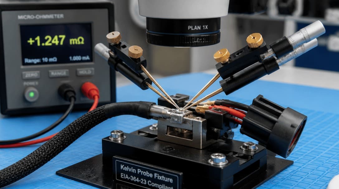
Electrical acceptance for a fretting-prone connector must be anchored to low-level contact resistance testing. EIA-364-23 is the low-level contact resistance test procedure for electrical connectors and sockets; IEC 60512-2-1 is the corresponding international measurement method. Both limit open-circuit voltage and current to levels low enough that the test will not break through thin oxide films that cause field intermittency. Higher-current or higher-voltage continuity tests can mask exactly the thin oxide and debris layer responsible for intermittent opens.
Pass/fail should be evaluated after thermal cycling, vibration, and humidity exposure. Record the average contact resistance change, the maximum end-point excursion, and any transient open circuit during testing. A single high-resistance spike or an open circuit during a low-level test is a failure even if the final resistance value recovers.
IPC/WHMA-A-620 defines acceptance criteria for crimp, insulation support, and assembly workmanship in wire harness and cable assemblies. That visual and dimensional acceptance is necessary, but it cannot detect wipe-track fretting degradation. A harness that passes IPC/WHMA-A-620 visual inspection can still carry a connector with plating wear inside the contact zone. For custom cable assembly builds, the same low-level contact resistance pass/fail criteria should be applied at the connector-to-cable interface, not only at the separable connector. If the selected tin, selective gold, or duplex plating cannot meet low-level contact resistance after simulated micro-motion, the plating, lubrication, or normal force design must be revised before release.
Writing Supplier Plating-Thickness Acceptance Requirements Before Release
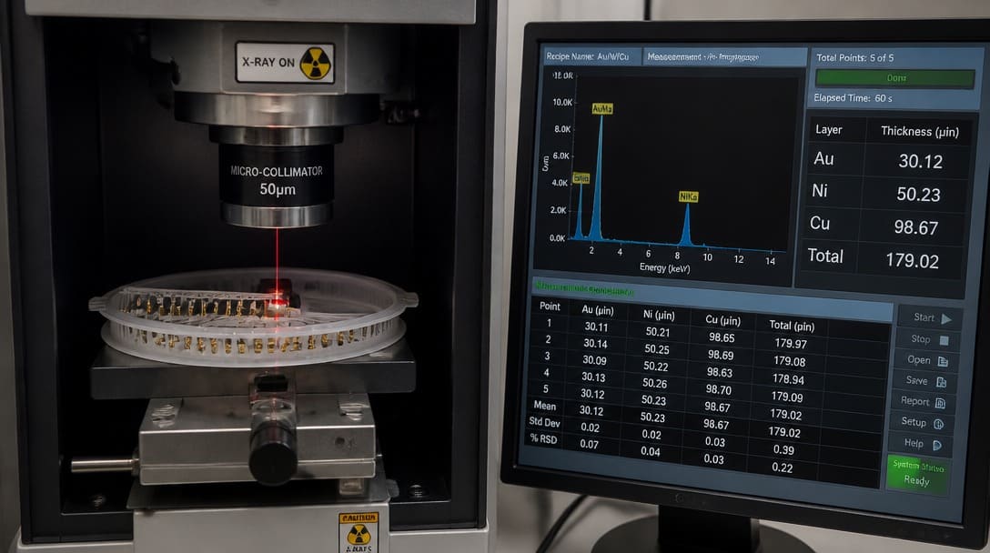
Plating thickness must be specified at the contact zone, not simply as an overall barrel or spot thickness. A supplier drawing should define minimum gold plating thickness in the wipe track area and pair it with a minimum nickel underplate thickness. For tin systems, the drawing should define minimum tin thickness and underplate condition. Verification must use X-ray fluorescence or microsection at the contact zone. Visual appearance is not an acceptable thickness verification method.
Mixed-metal assemblies require a printed acceptance limit. An uncontrolled tin-to-gold separable interface should be prohibited. Selective gold transition zones must be called out with the plating thickness and transition line on the drawing. Production samples or test coupons should define plating thickness measurement locations, sample size, frequency, and data retention for incoming inspection. The supplier acceptance plan should also tie plating thickness to the same low-level contact resistance and thermal/vibration sequence used pre-production, so thickness is validated against functional performance rather than measured only in isolation.
Suppliers such as EDOM Electronics support OEM buyers with requirement review, connector matching, sample coordination, production follow-up, inspection, and export-ready packaging for custom cable assemblies and wire harnesses. When a drawing requires selective gold in the wipe track and tin on termination tails, that transition must be clearly marked before sample confirmation. The same plating requirement should also travel into custom cable assembly and final inspection and export packaging documentation so that incoming inspection and outgoing quality control use the same acceptance criteria.
Pre-Release Field-Failure Screening Checklist for Terminal Plating Fretting Corrosion
Before a connector moves from prototype release to stable supply, run this screening checklist:
- Mating metal pair: confirm there is no uncontrolled tin-to-gold separable interface anywhere in the connector or harness.
- Plating thickness across the wipe track: request XRF mapping or microsection; do not accept only barrel or spot thickness data.
- Nickel underplate condition: verify underplate continuity and thickness, especially at wipe-track edges.
- Normal force and terminal geometry: confirm the terminal beam design, base material temper, and deflection produce adequate contact pressure for the selected plating system.
- Lubricant strategy: verify any anti-fretting lubricant is specified for the full operating temperature range and has defined coverage.
- LLCR after thermal/vibration exposure: require EIA-364-23 low-level contact resistance data after the same environmental sequence that simulates the field application.
Release gates should be built into the approval process. Any mixed tin/gold separable interface, any LLCR drift above the agreed threshold, or any visible wear-through to the nickel underplate in microsection triggers a redesign or supplier corrective action. For field-return screening, ask for micro-motion amplitude from thermal expansion mismatch, connector chatter, or harness routing, and request XRF mapping of the wipe track if the pins look visually clean. The broader connector overview at what is a connector: a practical overview for OEM buyers can be used to cross-check other connector selection criteria before moving from prototype to stable supply.
What Nobody Tells You: Hidden Plating Thickness Variation, Mixed Tin/Gold Interfaces, and Micro-Motion Amplitude
Three non-obvious failure mechanisms routinely undermine standard pass/fail efforts. The first is hidden plating thickness variation. Barrel and edge effects, thin nickel underplate at wipe-track edges, and selective gold misregistration can create localized failure sites that pass standard incoming visual inspection. XRF mapping across the entire contact zone catches these problems before they become field returns.
The second is the false assumption that gold-to-tin behaves like gold-to-gold. Tin oxide debris can transfer onto a gold surface and produce high contact resistance even though gold itself is noble. A noble gold finish does not protect the interface from the oxide generated by a mating tin terminal. Mixed-metal design review must treat tin-to-gold as a fretting risk, not as a convenient cost-reduction option.
The third is micro-motion amplitude. Fretting damage can occur at displacements of only a few microns from thermal expansion mismatch or vibration. Even a visually secure connector can generate enough relative motion inside the contact to produce wear debris and oxide accumulation. A visually clean pin is not a clean bill of health. The failure signature lives in the wipe-track plating thickness data and the low-level contact resistance trend after micro-motion simulation.
Frequently Asked Questions
How do I tell fretting corrosion from ordinary oxidation on a terminal?
Ordinary oxidation is a surface film that forms on exposed metal, often across the terminal body. Fretting corrosion appears inside the wipe track as wear debris, oxide accumulation, or exposed underplate after micro-motion. Low-level contact resistance testing and XRF mapping of the wipe track separate the two mechanisms.
Is tin plating always unsuitable for vibration environments?
Not always, but tin is more demanding mechanically. Tin requires high normal force to rupture tin oxide and is less tolerant of sustained micro-motion. It can work in low mating cycle, sealed, or stable harness applications, but it must not be mixed with gold across a separable connector interface.
Can mixing tin and gold terminals ever be acceptable in a separable connector?
Tin-to-gold separable interfaces should be prohibited unless the design has a defined transition line that keeps gold in the wipe track and tin on termination tails. An uncontrolled tin-to-gold separable interface is a galvanic and oxide-transfer risk that can produce intermittent opens over time.
What measurement method catches fretting corrosion before field failure?
Low-level contact resistance testing per EIA-364-23 or IEC 60512-2-1 is the preferred method. It limits open-circuit voltage and current so the test does not break through thin oxide films that continuity testing can mask. Pass/fail should be recorded after thermal cycling, vibration, and humidity exposure.
Should a supplier provide plating thickness data for every production lot?
For fretting-sensitive applications, plating thickness measurement locations, sample size, and frequency should be defined in the supplier acceptance plan. Suppliers that support requirement review, connector matching, sample coordination, and inspection can help OEM buyers keep plating data tied to the same low-level contact resistance test sequence used during pre-production.
Key Takeaways
- Terminal plating fretting corrosion is caused by micro-motion between mating connector surfaces generating non-conductive wear debris and oxide accumulation inside the wipe track, not by terminal appearance.
- Plating selection must match the mating cycle count, normal force capability, and vibration profile; tin requires high normal force, while gold offers stable low-level contact resistance when paired with a nickel underplate.
- Normal force, terminal geometry, strain relief, harness routing, and anti-fretting lubrication are the practical mechanical controls that reduce micro-motion amplitude and oxidation.
- EIA-364-23 / IEC 60512-2-1 low-level contact resistance testing is non-negotiable because standard continuity tests can mask the thin oxide and debris layer responsible for intermittent opens.
- Supplier plating acceptance must specify XRF or microsection verification in the wipe track, prohibit uncontrolled tin-to-gold separable interfaces, and tie thickness data to functional LLCR performance.
For OEM projects that require connector selection, specification review, and supply coordination, explore electronic connector sourcing support.