Quick Answer
An insulation piercing connector (IPC) is a termination device that makes electrical contact by cutting through the wire’s insulation, eliminating the need to strip the conductor beforehand. It is not a universal connector—the piercing blade must match the exact wire gauge, strand count, insulation material, and insulation thickness to achieve and maintain a reliable gas-tight joint over the product lifecycle.
What Is an Insulation Piercing Connector?
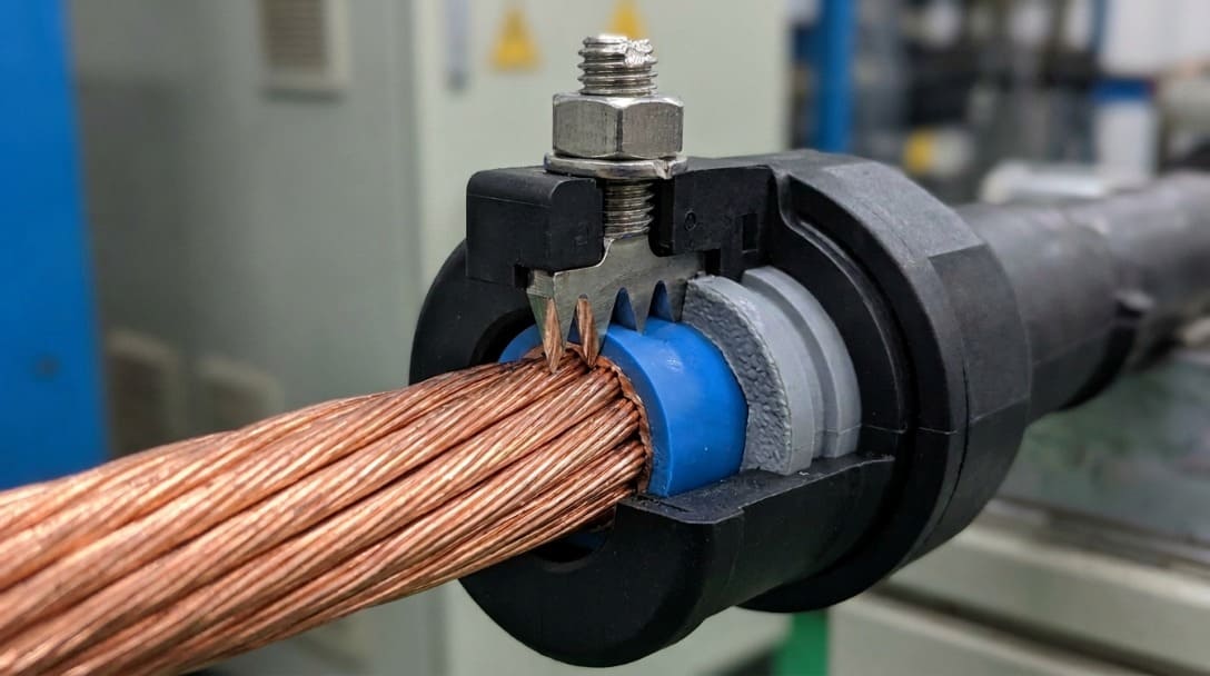
An insulation piercing connector establishes a conductive path by driving a sharpened metal blade or pin through the insulation jacket and into the copper conductor. Unlike crimp or solder joints, the installer does not remove any insulation; the connector’s piercing element penetrates the outer layer and embeds itself into the metal strands or solid core. The concept is widely used in automotive wire harnesses, industrial control enclosures, LED lighting chains, and appliance internal wiring, where it can slash per-connection time and simplify semi-automated assembly.
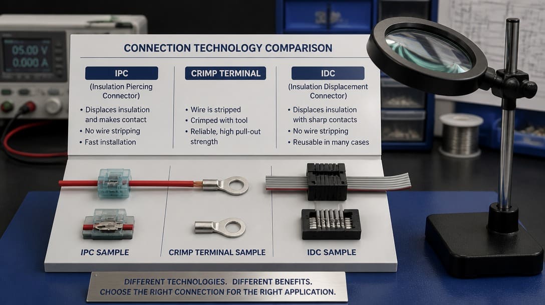
IPC designs are distinct from insulation displacement connectors (IDCs). While IDCs also avoid stripping, they typically squeeze a conductor into a narrow slot to displace insulation, whereas true IPCs use a dedicated piercing tip that enters the insulation at a controlled depth. This difference matters for vibration resistance, contact force retention, and long-term corrosion behavior.
How Does the Piercing Mechanism Work, and Why Does Wire Compatibility Matter?
The piercing element is engineered for precision. Its shape—often a triangular or needle-like point—governs how cleanly it perforates the insulation and how much conductor material it displaces. Base metal selection and plating (typically tin over brass or phosphor bronze) influence both insertion force and long-term contact integrity. If the blade is too blunt, it may compress the insulation without reaching the conductor, causing an intermittent open circuit. If it is too aggressive, it can sever strands or create stress risers that lead to fatigue failure.
Wire compatibility extends far beyond the nominal gauge. A connector approved for 0.5 mm² stranded wire may fail on a different construction with the same cross-sectional area if the strand count varies. Solid conductors behave differently under piercing force; a sharp tip can crack a solid core, reducing load-bearing area. The insulation material and its thickness are equally critical. Soft compounds such as PVC and TPE pierce differently than tougher, more elastic materials like XLPE or silicone. Even small variations in wall thickness—common across reel lots—can alter penetration depth enough to degrade the gas-tight seal. Leading interconnect suppliers such as Molex, TE Connectivity, JST, Amphenol, and Hirose publish detailed approved-wire tables that specify the acceptable range of insulation outer diameter and material family. Using a wire outside those tables is the single most common cause of IPC field returns.
Procurement teams often picture insulation piercing connectors as a drop-in replacement for stripped crimp connections, but the piercing mechanism’s tolerance window is narrow. Matching the connector to the exact wire construction is not just a best practice—it is the fundamental prerequisite for a reliable joint.
What Are the Trade-offs Between Installation Speed and Long-Term Reliability?
IPCs can cut per-termination time by up to 60% compared with a manual strip-and-crimp sequence. No wire stripping means no nicked conductors, no stray whiskers, and a cleaner work area. For high-volume wire harness manufacturing, this labor reduction translates into measurable savings on the assembly line and reduces ergonomic strain associated with repetitive strip-and-terminate movements.
However, that time advantage does not come free. Reliability hinges on the quality and consistency of the piercing operation. If the piercing depth deviates even slightly—due to insulation tolerance, tool wear, or operator variation—contact resistance can climb. In environments with vibration, thermal cycling, or humidity, a marginal pierce may gradually degrade through fretting corrosion or insulation cold flow. Unlike a properly crimped joint that generates a large area of cold-welded metal, an IPC maintains contact through a small number of high-pressure points; any loss of clamping force rapidly increases resistance. Total installed cost calculations must therefore include not just the piece-price and labor savings, but also the hidden cost of potential rework, higher field return exposure, and possibly extended warranty reserves if the application pushes the connector’s envelope.
What Are the Key Selection Criteria: Wire Gauge, Insulation Type, and More?
A structured evaluation should start with the data sheet, not the promotional promises. Below is a decision framework for technical teams reviewing IPC options.
| Selection Factor | Key Questions to Verify |
|---|---|
| Wire gauge and strand count | Does the connector’s approved list include the exact AWG/mm² and strand construction (solid or stranded, number of strands)? |
| Insulation material | Is the insulation family (PVC, PE, XLPE, FEP, etc.) explicitly listed? Does the material exhibit notable cold flow (creep) tendency? |
| Insulation thickness tolerance | What is the range of outer diameter accepted? Does the production wire vary within reel-to-reel limits? |
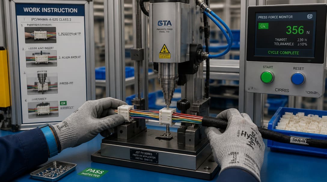
| Insertion force and tooling | Is hand insertion feasible for the required volume, or is a pneumatic/press tool necessary? What are the ergonomic implications for operators? |
| Environmental sealing | Is a gel-filled or IP-rated sealed housing required? Will the connector be exposed to moisture, salt spray, or thermal shock? |
| Standards and certifications | Does the connector carry UL component recognition? Are materials RoHS[1] compliant? Has the supplier performed EIA-364 test sequences? |
Connector suppliers frequently reference EIA-364 test methods when publishing reliability data. A thorough qualification report should include vibration, thermal cycling, and humidity aging results, not just initial contact resistance. Without this data, a procurement team is gambling on the connector’s ability to survive the vehicle or machine’s service life.
What Are Common Failure Modes, and How Can They Be Prevented?
IPC failures rarely appear on a first-article bench test. Many develop over hundreds of hours in the field. Understanding these patterns helps engineering teams design more robust validation plans.
- Partial or incomplete piercing. The blade does not fully penetrate dense or thick insulation. Initial continuity checks may pass, but a high-resistance path forms under load, creating intermittent opens. Root cause is usually a mismatch between insulation thickness and the connector’s maximum penetration depth.
- Insulation cold flow (creep). Under sustained pressure, certain insulations slowly extrude away from the blade contact points. This reduces the normal force holding the blade against the conductor, causing a gradual resistance increase that can culminate in thermal runaway. Connectors validated on rigid PVC may behave very differently when applied to softer, lower-durometer TPE.
- Vibration-induced contact degradation. Mechanical resonance can cause microscopic relative motion at the blade-wire interface, leading to fretting corrosion. This is particularly dangerous in engine compartments and industrial machinery. Design verification testing following EIA-364 vibration sequences is essential.
- Thermal cycling effects. Differences in the coefficient of thermal expansion between the conductor, insulation, and connector body can loosen the piercing joint over repeated heating and cooling cycles, especially if the connector body is not designed to compensate for these movements.
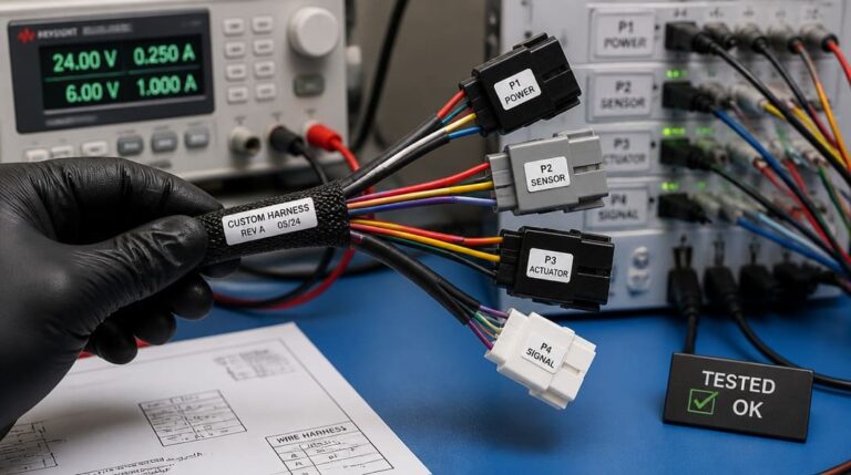
Mitigating these risks demands more than a datasheet comparison. Engineering teams should prototype with actual production wires—not generic lab samples—and run a subset of connectors through accelerated stress testing before committing to procurement. When evaluating custom cable assembly projects that incorporate IPCs, it is common to see suppliers apply continuity testing immediately after termination and again after a vibration or thermal shock procedure, exactly to catch infant-mortality failures that are invisible on a static bench check. For deeper guidance on how these verification steps integrate into a broader production flow, many procurement teams refer to resources like quality inspection and export packaging protocols that detail checkpoints from in-process crimp/pierce force monitoring to final outgoing audits.
How Do Insulation Piercing Connectors Compare to Traditional Termination Methods?
The decision between IPCs and conventional strip-and-crimp terminations often rests on a combination of project volume, wire mix, and reliability requirements. No method is universally superior; each excels under specific conditions.
| Parameter | Insulation Piercing Connector | Manual Strip-and-Crimp (Open Barrel) |
|---|---|---|
| Typical installation time per connection | 2–3 seconds (hand insertion or press) | 7–10 seconds (strip, position, crimp) |
| Wire preparation | None | Stripping tool required; risk of nicked strands |
| Contact reliability | High when applied within strict tolerance window; sensitive to insulation variation | Proven gas-tight crimp across wide range of wire constructions when properly calibrated |
| Field failure risk | Increased if piercing parameters are not tightly controlled or if insulation creep occurs | Low with correct tooling and pull-test verification; dominated by terminal/crimp quality |
| Tooling investment | Often requires connector-specific application tooling or press | Standard crimp tools cover multiple terminal families |
| Suitability for mixed wire types | Limited; each connector variant covers a narrow gauge/insulation range | Flexible; different terminals can accommodate varied wire sizes on the same line |
| Reference standards | EIA-364 sequences; supplier-approved wire lists | IPC/WHMA-A-620; UL486A/B for terminal performance |
Data from major interconnection system providers such as Molex, TE Connectivity, and JST illustrate that IPCs deliver their best cost-performance ratio in high-volume, single-wire-type applications where production line repeatability is tightly controlled. In complex wire harness manufacturing environments that mix multiple AWG sizes and insulation families, the changeover effort and risk of mismatch may shift the economic case back toward traditional crimp processes, especially when automated stripping and crimping machines are already in place.
What Should Procurement and Engineering Teams Include in Their Evaluation Checklist?
Bringing IPCs into a production program requires a deliberate qualification process, not just a vendor visit. The following checklist translates the failure mechanisms and selection criteria into concrete actions.
- Confirm wire gauge, strand count, and insulation material against the connector supplier’s approved wire list. Do not rely on nominal gauge alone; request the exact part number or wire specification.
- Validate insulation thickness tolerance across the wire supplier’s reel-to-reel variation. A maximum/minimum diameter tolerance stack-up should fall inside the IPC’s stated operating window.
- Assess insertion force and request tooling recommendations—whether hand tool, pneumatic press, or dedicated application turret—along with sample tools for trial runs.
- Review qualification data from the connector supplier: EIA-364 test reports covering vibration, thermal cycling, and humidity aging for the specific wire combination intended for production.
- Evaluate environmental sealing needs. Unsealed IPCs may be adequate for protected indoor enclosures, but harsh environments demand sealed or gel-filled housings to achieve the target IP rating.
- Calculate total installed cost including not only piece-price and direct labor, but also estimated rework rates, potential field return impact, and line changeover time when switching between wire types.
- Prototype with actual production wires and housings. Measure initial contact resistance and repeat after a short stress-testing sequence (e.g., 20 thermal cycles and a vibration sweep) to detect early degradation.
- If the program involves custom cable assembly or wire harness manufacturing, integrate the IPC qualification into the supplier’s normal process control plan, including in-process inspection of pierce depth and post-termination continuity testing.
Frequently Asked Questions
Is an insulation piercing connector the same as an insulation displacement connector?
No. Insulation displacement connectors (IDCs) use a narrow slot to push insulation aside and grip the conductor, while insulation piercing connectors use a sharpened tip to penetrate the insulation directly. The piercing action creates a different contact geometry and has distinct requirements for insulation material compatibility.
Can IPCs be reused if the connection is removed?
Generally not. Once a blade has pierced and plastically deformed both the insulation and the conductor, reinserting a new wire—even of identical specification—may result in reduced contact force because the sharp edges have already been loaded. Most manufacturers recommend single-use only.
What certification should I look for when sourcing IPCs?
Look for UL component recognition, RoHS compliance, and supplier test data per EIA-364. For automotive or industrial applications, ask for qualification reports that include vibration and thermal cycling results.
How do I verify that the piercing depth is correct during production?
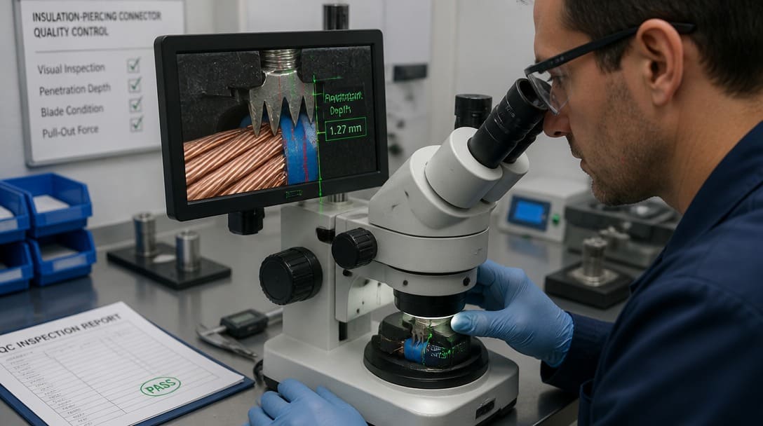
Production monitoring can combine insertion force profile analysis (via press sensors) with periodic cross-sectioning of samples to measure blade embedment. Visual inspection alone cannot catch incomplete piercing. Integration of these checks is part of a comprehensive quality inspection and export packaging strategy.
Key Takeaways
- An insulation piercing connector is a precision termination device; it is not a universal drop-in replacement for stripped connections.
- Successful application depends on matching the connector to the exact wire gauge, strand count, insulation material, and insulation thickness, as defined in supplier-approved wire lists from companies like Molex, TE Connectivity, JST, Amphenol, and Hirose.
- The labor savings from eliminating strip time can be significant, but total cost calculations must account for reliability risks if IPC parameters are not strictly controlled.
- Common failure modes—partial piercing, insulation cold flow, vibration-driven fretting—can be mitigated through rigorous EIA-364 testing and prototyping with actual production wires.
- A thorough evaluation checklist that includes qualification data, tooling assessment, and environmental sealing requirements protects both procurement and engineering teams from unpleasant field surprises.
For wire harness and cable projects that demand tightly controlled termination processes, understanding the role of matched connectors is only the first step. Learn more about our wire harness OEM services and how connector selection integrates into full production engineering.