Copper-clad aluminum (CCA) wire is a conductor material composed of an aluminum core metallurgically bonded with an outer copper layer, used as a lighter, lower-cost alternative to solid copper in cable assemblies and wire harnesses where current load, flexing, termination compatibility, and thermal cycling are carefully controlled.
A procurement manager is reviewing a supplier-submitted BOM where solid copper conductors have been replaced with copper-clad aluminum (CCA), and the pre-production sample has passed bench continuity. The immediate requirement is not a general material comparison but a defensible go/no-go sourcing decision before purchase order sign-off. Passing bench continuity or visual inspection is not evidence of conductor-material compliance or long-term termination integrity.
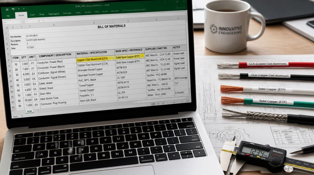
How to Make a Defensible Copper vs CCA Sourcing Decision Before PO Sign-Off
Step 1: Confirm the Application Operating Conditions and Sourcing Variables
Start by extracting the operating conditions from the application drawing, schematic, and field environment. CCA has higher electrical resistance than solid copper for the same American Wire Gauge (AWG), so the same harness length produces greater voltage drop unless the AWG is upsized. CCA is also lighter and lower cost, but that advantage only matters when the circuit can tolerate reduced conductivity.
Before going further, review the broader wiring harness overview to confirm which harness sections carry the substituted conductors and whether they sit in static routing or moving/flexing zones.
- Record maximum steady-state current and inrush current.
- Record installed length and acceptable voltage drop limits.
- Classify each harness segment as static routing, occasional flex, or continuous flex.
- Record expected temperature cycling exposure, including ambient and connection hot spots.
Standard Physical & Electrical Benchmarks (Pure Copper vs. CCA)
| Engineering Parameter | Annealed Pure Copper (ASTM B3 / IEC 60028) | CCA Class 10A (ASTM B566) | CCA Class 15A (ASTM B566) | Engineering Risk Implication |
|---|---|---|---|---|
| Minimum Conductivity (% IACS @ 20°C) | 100.0% | 64.4% | 68.8% | Requires 1–2 AWG size up to maintain equivalent circuit voltage drop |
| Nominal Density (g/cm³) | 8.89 | 3.32 | 3.63 | Basis for rapid dockside weight verification (~60% lighter than copper) |
| Maximum Volume Resistivity (nΩ·m @ 20°C) | 17.241 | 26.77 | 25.06 | Direct driver of thermal runaway under continuous high-duty power loads |
| Tensile Strength (MPa, Annealed) | 200 – 250 | 103 – 138 | 117 – 152 | Terminal pull-off force drops; standard pure copper crimp profiles tear CCA strands |
| Galvanic Potential vs. Brass/Tin | Near neutral | High differential (>0.5V at cut ends) | High differential (>0.5V at cut ends) | Severe galvanic oxidation of aluminum core in humid or marine operating zones |
Step 2: Score the Substitution Using the CCA vs Copper Go/No-Go Decision Tool
Apply the decision tool below. Each row is a go/no-go gate, not a weighted scorecard: if any high-risk field falls into caution or reject, the substitution should not proceed without additional derating, test data, and engineering acceptance.
| Decision factor | CCA may pass | Caution / reject |
|---|---|---|
| Application current | Low-current static signal or control circuits with stable load | High-current, motor, heater, power distribution, or inrush-prone circuits |
| Flexing / movement | Fixed routing with minimal vibration | Repeated flexing, moving harness sections, or routing through hinges |
| Temperature cycling | Narrow temperature range, stable ambient, limited heat excursions | Wide thermal cycles, outdoor exposure, engine/battery-adjacent locations |
| Length / voltage drop | Short runs where upsizing AWG and increased voltage drop are acceptable | Long runs, low-voltage circuits with tight drop budgets, or end-device minimum voltage requirements |
| Required verification evidence | Supplier provides material-specific resistance or density data and IPC/WHMA-A-620[1]-compliant crimp evidence | Supplier offers only continuity, visual inspection, or generic “CCA approved” statements |
The tool output is a commercial decision record for the purchase order file, not a replacement for engineering validation.
Step 3: Require Material-Specific Verification Evidence Before Accepting CCA
Continuity testing or visual appearance checks do not verify that the conductor is CCA rather than solid copper, and they cannot predict whether crimp terminations will remain gas-tight over thermal cycles. For a defensible sign-off, demand material-specific evidence tied to the correct standards.
- Request conductor resistance or density data against ASTM B566, which covers copper-clad aluminum wire construction, and IEC 60228[2], which defines conductor classes and resistance expectations.
- Require IPC/WHMA-A-620-compliant crimp pull-force and cross-section data for CCA terminations tested after thermal cycling. IPC/WHMA-A-620 defines three acceptance classes with increasing inspection and documentation rigor; confirm which class applies to the finished harness.
- Where UL listing or recognized-component status is required for the finished harness or assembly, verify that the CCA conductors are acceptable within the listing conditions.
- Ask the supplier to document process controls: crimp height, conductor preparation, plating interfaces, and any anti-oxidation or joint compound steps.
Receiving Dock Fast Screen: 3 Practical Methods to Detect Disguised CCA
- The Butane Flame Exposure Test: Strip 15 mm of insulation and expose bare strands to an open butane torch or lighter flame (flame temperature ~800°C–1000°C) for 2 to 3 seconds. Pure copper (melting point 1085°C) glows red, retains its strand bundle shape, and cools with a dark oxide coating. CCA fails almost instantly: the inner aluminum core (melting point 660°C) liquefies, droops, and puddles, leaving only a hollow, crumpled copper foil shell.
- The Mechanical Scraping Test: Shave the outer surface of a single conductor strand at a shallow angle with a clean utility blade. Pure copper maintains its solid red/orange hue across the entire cut depth. CCA immediately exposes a bright, silver-white aluminum core.
- Precision Density/Weight Verification: Cut a precise 10.0-meter sample of stripped conductor and weigh it on a 0.01g balance. Because pure copper density is 8.89 g/cm³ versus 3.32–3.63 g/cm³ for CCA per ASTM B566, an undocumented CCA substitution will show an unmistakable ~58%–62% weight reduction against the drawing’s copper weight baseline.
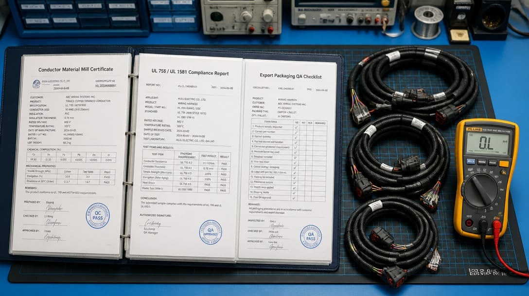
This is also the point to review the supplier’s quality inspection and export packaging controls, because material evidence alone does not cover handling, contamination, or shipment-related termination risk. A production-coordinated cable assembly and wire harness supplier such as EDOM Electronics can support OEM buyers, as outlined in What Wiring Harness Do I Need?, with requirement review, connector matching, sample coordination, production follow-up, inspection, and export-ready packaging for custom cable assemblies and wire harnesses.
Step 4: Normalize Quotes for Like-for-Like Commercial Comparison
CCA pricing looks lower before sign-off, but the real cost includes AWG upsize, changed termination processes, additional testing, and field risk. Build a true CCA cost equation: quoted unit price plus added verification, derating or upsize, and a field-risk reserve compared with the solid copper baseline.
- Ask the supplier to separate conductor material, termination method, and compliance documentation costs in the BOM line items.
- Check whether the quote includes thermal cycle crimp testing, cross-section analysis, and documented IPC/WHMA-A-620 inspection.
- For harness production, confirm whether the supplier’s wire harness manufacturing process can handle the added CCA prep steps without creating uncontrolled variation.
Step 5: Document the Final PO Conditions or Rejection Response
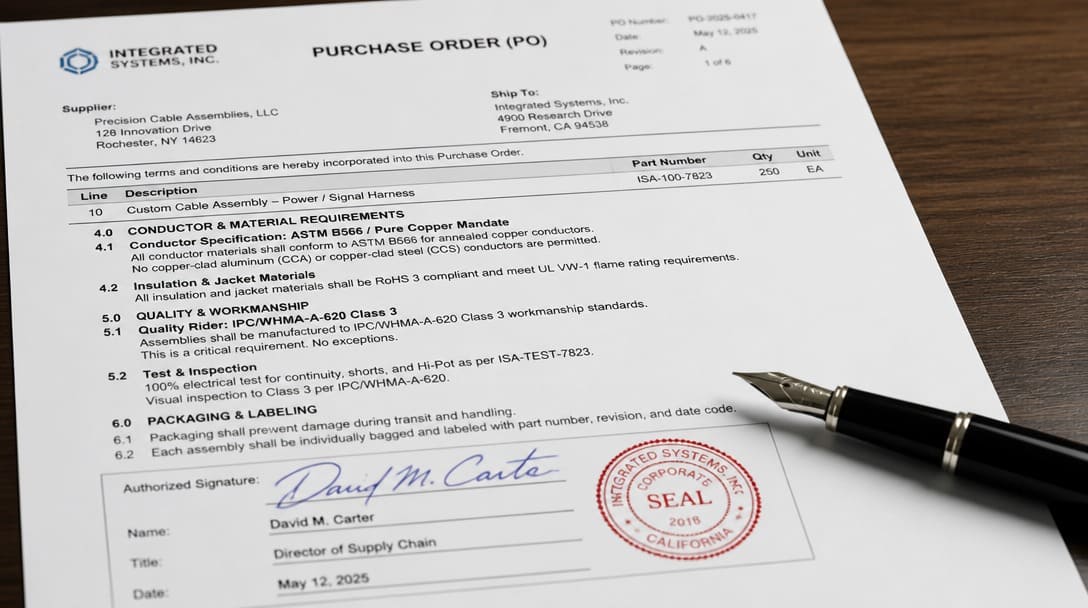
If CCA passes with conditions, put them on the purchase order and related engineering documents: conductor standard (ASTM B566 or equivalent), exact AWG, termination methods, IPC/WHMA-A-620 class, and required test report submissions. If solid copper remains required, prepare a supplier response naming the technical reason and the requalification evidence needed before reconsideration.
Before final release, return to the broader wiring harness overview to re-check harness-level routing, strain relief, and termination decisions outside the conductor material question.
What Goes Wrong in the Field: Failure Modes Invisible at Incoming Inspection
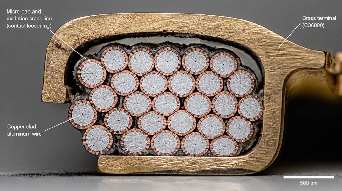
The most catastrophic field failures in CCA assemblies stem from three metallurgical realities that pre-production bench continuity tests cannot detect:
- Mechanical Creep and Stress Relaxation: Unlike copper, aluminum undergoes significant room-temperature stress relaxation under continuous compressive crimp loads. Over time, the radial contact force exerted by the terminal’s wire barrel drops, compromising the initial gas-tight seal even without thermal cycling.
- Galvanic Corrosion at Raw Cut Edges: Stripping and cutting CCA leaves the inner aluminum core exposed to the atmosphere. When crimped against copper, brass, or tin-plated terminals in ambient moisture (>60% RH), the significant electrochemical potential gap between copper and aluminum forms a galvanic cell. The aluminum core corrodes into powdery, non-conductive aluminum oxide (Al₂O₃), causing rapid contact resistance spikes.
- Thermal Shock CTE Mismatch: Aluminum has a high coefficient of thermal expansion (
23 × 10⁻⁶/K) compared to brass terminals (19 × 10⁻⁶/K) and copper (~16.5 × 10⁻⁶/K). Repeated thermal cycling creates micro-movement across the crimp interface, pumping oxygen into voids and accelerating contact degradation. - Soldering Incompatibility: In applications requiring tinning or PCB through-hole soldering, typical fluxes and molten solder dissolve the thin outer copper layer within seconds. Once exposed, molten solder cannot wet the underlying oxidized aluminum without highly aggressive fluxes that introduce long-term chemical corrosion risks.
This is why IPC/WHMA-A-620 termination workmanship requirements focus on measurable mechanical and material parameters rather than continuity alone. A visual inspection can confirm that the crimp looks fully formed, but it cannot reveal whether the CCA-to-terminal interface will survive hundreds of thermal cycles. Reduced flex-life failures appear in moving harness sections that may look fine on a static sample but fail after installation and repeated routing.
Field failures from these mechanisms often appear weeks or months after final verification, which is why the sign-off decision must require material-specific evidence and thermal-cycle crimp data rather than pre-production continuity only.
Frequently Asked Questions
Can I accept a CCA substitution if the pre-production sample passes continuity testing?
No. Continuity only confirms an electrical path at the test moment. It does not verify conductor material, crimp gas-tightness over thermal cycles, or compliance with IPC/WHMA-A-620. Demand ASTM B566 or IEC 60228 material data and thermal-cycle crimp pull-force and cross-section results.
Does CCA require an AWG upsize compared with solid copper?
CCA has higher resistance than solid copper for the same American Wire Gauge, so an upsize is often necessary to meet equivalent ampacity or voltage drop limits. The required AWG depends on current, run length, allowable temperature rise, and termination capacity.
Is CCA acceptable for automotive or high-temperature applications?
CCA may be acceptable only in limited low-current static circuits with documented verification. Wide temperature cycling, vibration, and high-current paths generally call for solid copper unless requalification data supports the substitution and UL listing conditions are satisfied.
What standards apply to CCA conductor acceptance?
ASTM B566 covers copper-clad aluminum wire construction; IEC 60228 defines conductor classes and resistance expectations; and IPC/WHMA-A-620 sets acceptance requirements for crimp and termination workmanship. UL listing requirements are separate and must be checked for the finished harness or assembly.
How should buyers compare CCA and copper quotes fairly?
Normalize quotes by adding AWG upsize, termination process changes, testing and verification costs, and a field-risk reserve to the CCA unit price. Compare that true cost against the solid copper baseline with documented compliance, rather than comparing raw unit prices.
Key Takeaways
- CCA is a legitimate lower-cost option only when application current, flexing, temperature cycling, length, and required verification evidence all pass the go/no-go decision tool.
- Passing bench continuity or visual inspection is not evidence of conductor-material compliance; require ASTM B566 / IEC 60228 material data and IPC/WHMA-A-620 thermal-cycle crimp results.
- Normalize CCA prices with AWG upsize, termination changes, testing, and field-risk reserve before comparing with solid copper.
- Document any CCA acceptance conditions directly on the purchase order, including conductor standard, AWG, termination method, IPC/WHMA-A-620 class, and test report requirements.
- For a complete harness-level review beyond conductor material, revisit the broader wiring harness overview before final release.
For OEM programs that need conductor sourcing, crimp qualification, and export packaging coordinated against drawings and BOMs, explore custom cable assembly solutions to review production follow-up and inspection options.