If you just received a drawing that says wire harness and you’re not sure what that means or what you need to prepare, this is the right place to start.
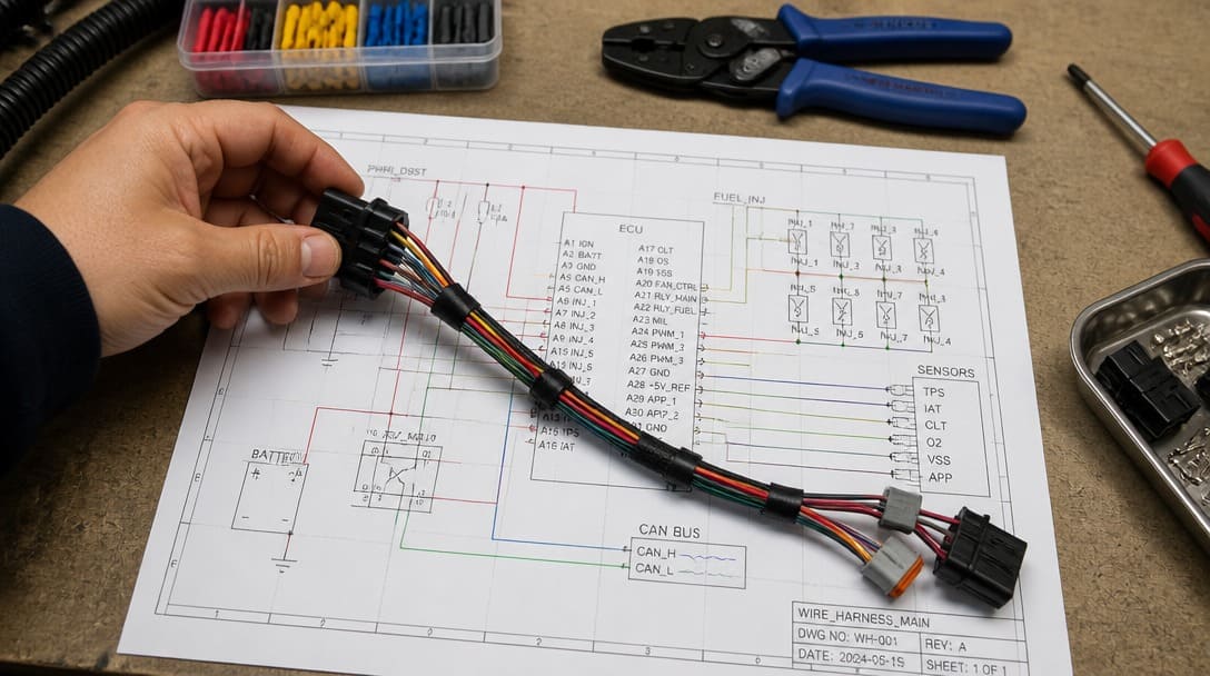
In short: A wire harness is a purposefully organized bundle of wires, terminals, connectors, and protective coverings that routes electrical power and signals through a piece of equipment. It is not a random collection of cables — each branch length, insulation type, connector pin, and label position is defined in advance to match the mechanical layout and electrical requirements of the final product.
What Is a Wire Harness? (And Why It’s Not Just ‘A Bunch of Wires’)
For anyone encountering a wire harness for the first time in a bill of materials or engineering drawing, the initial reaction is often the same: “It’s just some wires tied together.” In reality, a well‑designed wire harness is a structured electromechanical sub‑assembly. It replaces the spaghetti of individual loose wires that would otherwise fill an enclosure, improving serviceability, reliability, and assembly speed on the OEM production line.
A typical wire harness is built from a few core components: wires, connectors, terminals, and protective sleeving, as detailed in our guide to wiring harness components.
- Conductors. Most harnesses use stranded copper wire sized by AWG (American Wire Gauge). Stranding is chosen to balance flexibility, current capacity, and fatigue resistance. The insulation is usually defined by a UL style number — for example, UL 1007[1] or UL 1015 — which specifies voltage rating, temperature range, and material chemistry.
- Terminals. At each wire end, a metal terminal (spade, ring, pin, socket, or blade) is attached by crimping or soldering. Crimping, when controlled by pull‑force verification and dimension checks, is the dominant method in volume production.
- Connector housings. The terminated wires are inserted into plastic connector bodies that lock into corresponding mating connectors. Housings carry a defined number of poles, pitch, and keying so that circuits cannot be mis‑mated.
- Protective sleeving. Split conduit, braided loom, or heat‑shrink tubing is applied over wire bundles wherever abrasion, heat, or fluid exposure is expected.
- Identification labels. Heat‑shrink markers, wrap‑around labels, or printed sleeves are added to each wire or branch for traceability, matching the wiring diagram.
Regulatory considerations also enter the picture early. For shipments into the European Union, all materials in the harness must meet RoHS (Restriction of Hazardous Substances) requirements. While UL standards are common for North America, additional certifications apply for other markets. For aerospace-grade harnesses, our aerospace wire harness compliance guide covers further requirements.
Wire Harness vs. Cable Assembly: Why the Distinction Matters
One of the most persistent sources of confusion is the difference between a wire harness and a cable assembly. The two terms are used interchangeably in casual conversation, but they describe very different products with different manufacturing approaches and price structures. Knowing which one a drawing actually calls for prevents hours of wasted back‑and‑forth with potential suppliers.
| Characteristic | Wire Harness | Cable Assembly |
|---|---|---|
| Construction | Multiple loose wires bundled together, often with branches; wires follow a custom routing path on a form board. | One or more finished cables — each an inner conductor, insulation, shielding, and outer jacket — terminated with a connector or overmold. |
| Typical Environment | Inside an enclosure, protected from weather and direct liquid spray. Protection is mainly against abrasion, heat, and mechanical pinch points. | External interconnects, often between cabinets or in exposed areas. Chemical, moisture, and UV resistance are common requirements. |
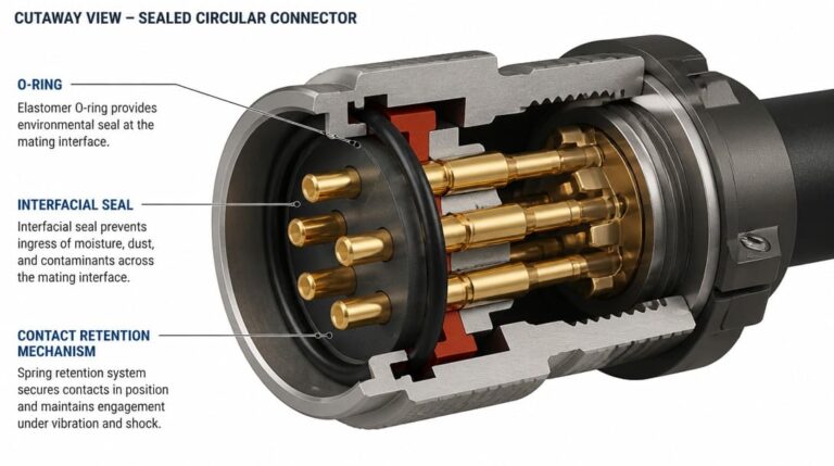
| Connector Style | Multi‑pin rectangular, circular, or blade connectors; often unsealed, or with minimal rubber seals. | Overmolded connectors, sealed circular connectors, or industrial‑grade plugs with IP67+ ratings. |
| Protection Level | Loom, conduit, spiral wrap, or heat shrink for grouping and light abrasion resistance. | Molded strain relief, environmental sealing grommets, and often a heavy‑duty outer jacket. |
| Testing Focus | Continuity, pin‑to‑pin mapping, pull‑test for crimps. | Continuity, hi‑pot, insulation resistance, and often environmental seal tests. |
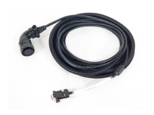
Many drawings labeled “wire harness” actually describe a simple cable assembly — a single overmolded cord with two connectors. Conversely, what looks like a cable assembly in a catalog picture might be a complex branched harness enclosed in conduit. Misclassifying the article at the inquiry stage can lead to pricing based on incorrect assumptions, which creates mistrust when the real quotation arrives later.
If uncertainty remains about which category a project falls into, arranging a design review with a cable and harness specialist can prevent costly miscommunication. For sealed, high‑protection interconnects, the custom cable assembly process provides insights on overmolding, jacketing, and environmental test considerations.

Why Wire Harness Projects Demand More Upfront Details Than You Expect
New buyers often treat a wire harness like a simple commodity — a spool of wire cut to length and stuffed into a connector. The reality is that every harness is a custom‑engineered item. No stock‑keeping unit exists until after the requirements are fully defined. This is why the initial inquiry frequently hits a wall: the supplier asks a long list of questions, and the buyer feels caught off guard.
In our experience, the first inquiry from a new buyer almost always arrives without a quantity. Without that one number, we can’t give a meaningful price — material costs shift significantly between 50 units and 500. Connectors, terminals, and custom wire colors carry minimum order quantities (MOQs) from their own manufacturers. A quoted price for 100 harnesses that includes absorbing a full reel of custom‑color wire is fundamentally different from the price for 1,000 units where that reel cost is amortized.
Beyond quantity, three other items routinely stall the quotation process: unclear specifications, custom components, and lead time expectations. For a comprehensive overview of the purchasing process, check our OEM harness wire purchasing guide.
- Wire specification. “Standard wire” is not a specification. The supplier must know the exact AWG, stranding count, insulation material (PVC, XLPE, silicone), and the UL style or equivalent temperature/voltage rating. A wire rated for 80°C under UL 1007 behaves very differently from one rated for 105°C under UL 1015, and substituting one for the other can create a warranty risk.
- Connector plating. The choice between tin, gold flash, or selective gold plating on connector contacts has a dramatic impact on unit price and long‑term reliability. Gold plating is specified in microinches — a 30‑microinch gold contact costs more than a gold flash but provides far longer corrosion resistance. If the drawing omits plating, the supplier does not know which grade to quote, and the default assumption may be either too expensive or insufficiently robust.
- Color requirements. A harness using only standard, off‑the‑shelf colors such as red, black, blue, and green avoids most dye‑lot minimums. If the design demands specific stripe patterns, pastel shades, or two‑color coding across all wires, the supplier must order custom wire, which introduces longer lead times and setup charges that dominate the bill of materials at low volumes.
Recognizing these variables early helps turn a hesitant inquiry into a productive conversation. When a buyer comes prepared to discuss quantities, plating, and any color constraints, the quotation can take hours instead of days.
The Exact Information a Supplier Needs to Give You a Real Quote
To move from a preliminary ballpark figure to a firm, executable quotation, the following pieces of information should be gathered before the first outreach. The more of these that are resolved, the less back‑and‑forth is required:
- Quantity. Annual volume, batch sizes, or a minimum forecast that unlocks tiered pricing. Even a rough range (e.g., 200–500 pieces) is far better than no number at all.
- Wire specifications. AWG size, stranding, insulation type (UL style number or equivalent), voltage and temperature rating, and color code for each circuit. If the wire must comply with SAE J1128 for low‑voltage primary wire, that should be stated.
- Connector details. Manufacturer part numbers, pin count, gender, pitch, and — crucially — plating type. If the exact part number is unknown, at least the mating connector series and intended use help a supplier narrow the search.
- Assembly structure. Overall length, branch lengths, routing path, and the specific pole assignments for each wire inside the connector body. A dimensioned drawing or a sample harness dramatically reduces ambiguity.
- Testing requirements. Mandatory tests such as 100% continuity verification, hi‑pot (dielectric withstand), and pull‑force testing on crimped terminals. If a specific workmanship standard applies, such as IPC/WHMA‑A‑620, it should be referenced so the supplier’s quality plan can align with the expected acceptance criteria.
- Environmental and regulatory markings. RoHS compliance status, flame rating (e.g., UL 94 V‑0 for sleeving), and any special labels required for import or end‑customer identification.
Suppliers such as EDOM Electronics use this structured information to verify design feasibility, cross‑check connector availability, and prepare a manufacturing plan that matches the buyer’s target quality level. A well‑prepared specification package is the single most effective way to shorten the quote‑to‑production window.
How Wire Harnesses Are Manufactured (A Brief Tour of the Production Floor)
Understanding the key manufacturing steps helps buyers see why early design decisions — such as leaving extra wire length for service loops — pay dividends during production. The following sequence covers the most common processes in an industrial wire harness factory.
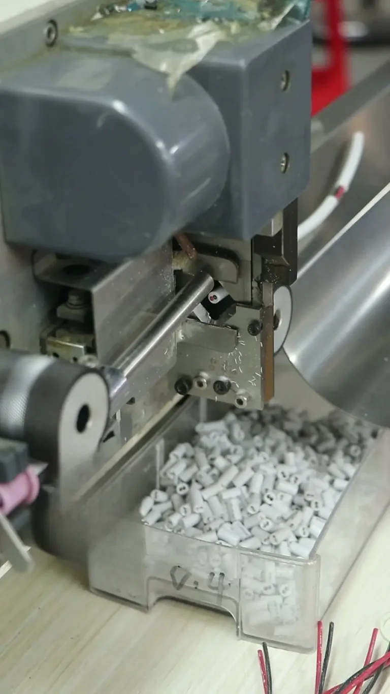
- Cutting and stripping. Bulk wire reels—produced by copper wire drawing and continuous annealing to precise conductor gauges—are loaded into automatic cutting‑stripping machines. Each wire is cut to the documented length, and the insulation is removed from both ends to the specified strip dimension. For low‑volume or prototype builds, manual measurement and hand tools are used.
- Crimping or soldering. Terminals are attached to the stripped wire ends. In volume production, crimping is performed with semi‑automatic press‑applicators that control crimp height and monitor pull force. Samples are periodically checked against IPC/WHMA‑A‑620 acceptance criteria to confirm deformation and tensile strength are within limits.
- Contact Insertion (Terminal Stuffing). The crimped or soldered terminals are carefully inserted into the plastic connector cavities according to the pinout configuration. An audible or tactile click confirms proper latch engagement, preventing terminal back-out under vibration.
- Routing and looming. Wires are laid onto a form board that replicates the final branch geometry. They are bundled together, and protective sleeving — expandable braid, split conduit, or heat‑shrink tubing — is slid over the appropriate sections. Cable ties or lacing cord keep the routing neat and strain‑free.
- Labeling and marking. Each wire and each connector receives its identification label. Heat‑shrink markers are applied with a hot‑air gun, while wrap‑around labels are positioned so they remain readable even as the harness flexes. The labels match the wire list, ensuring that every termination point is traceable.
- Testing. Every harness undergoes 100% continuity testing to verify pin‑to‑pin mapping. Depending on the project specification, additional tests may include hi‑pot (dielectric withstand) or functional checks. Visual inspection examines insulation damage, crimp appearance, label placement, and overall cleanliness. The acceptance standard — often IPC/WHMA‑A‑620 Class 2 or Class 3 — determines the severity of allowed imperfections.
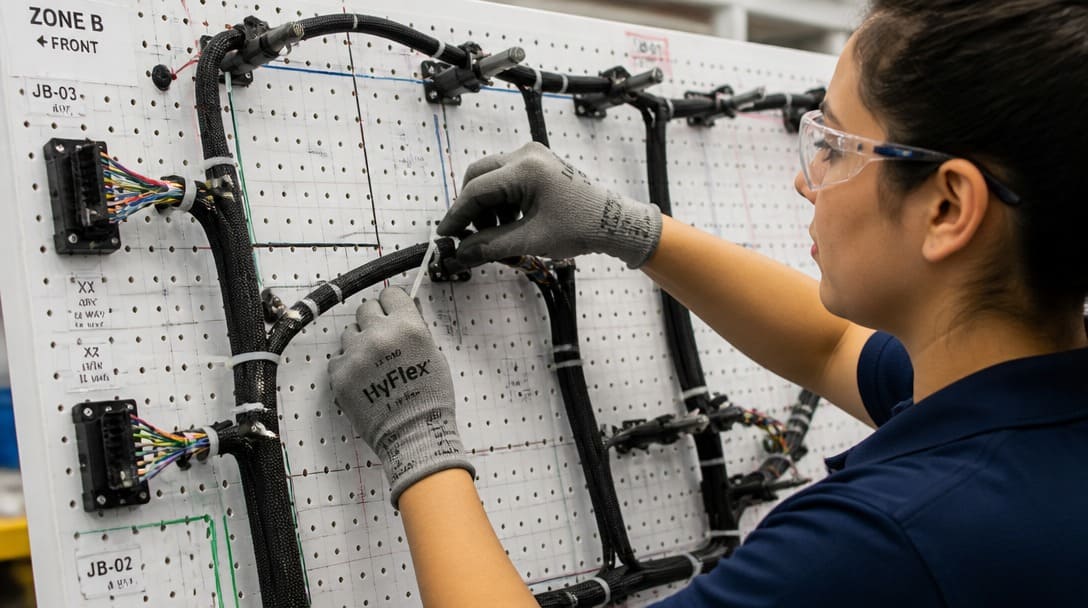
Each step relies on the documentation produced during the design phase. A clear drawing with wire lengths and connector pinouts eliminates guesswork on the form board. Ambiguity in the documentation directly translates into rework hours and delayed shipments.
Design Principles That Make OEM Wire Harness Assemblies Reliable
Reliability problems in wire harnesses rarely start on the factory floor; they originate at the design stage. Incorporating a few practical principles into the specification can prevent field failures and simplify future re‑orders.
- Map the true operating environment. Temperature extremes, vibration profiles, and exposure to oil or cleaning solvents dictate insulation material, sleeving type, and connector seal requirements. A harness that works inside a climate‑controlled cabinet will not survive if relocated near a hot engine or chemical washdown area.
- Include service loops. A small amount of extra wire length at each termination point reduces tensile stress on the crimp and allows the assembler room to work during first‑time build and later maintenance. Service loops also compensate for minor drawing deviations without requiring a harness revision.
- Standardize on off‑the‑shelf components. Whenever possible, choose connector families and AWG sizes that are readily available from major distributors. A fully custom connector — while precisely meeting a unique mechanical layout — often carries high tooling costs and minimum lot charges. Using standard housings, contacts, and wire colors reduces both lead time and the volume threshold for cost‑effective production.
- Specify the acceptance standard and test plan upfront. Stating “IPC/WHMA‑A‑620 Class 2” or “Class 3” tells the manufacturer the expected workmanship level. Class 2 covers general‑purpose electronic products; Class 3 demands tighter criteria for high‑reliability assemblies where intermittent operation is not acceptable. Pair this with a clear list of required tests — continuity, hipot, pull force — so that the quality plan matches the project risk profile.
- Document with unambiguous deliverables. A CAD drawing that includes a wire list, connector pinout table, and BOM references is far less prone to misinterpretation than a hand‑sketched mark‑up on a whiteboard. If a physical sample harness exists, shipping it to the supplier alongside the drawing removes nearly all dimensional uncertainty.
- Adhere to Minimum Bend Radius Constraints (IPC-A-620 Section 14). Sharp bends induce mechanical fatigue in copper strands and cause micro-cracks in PVC or silicone insulation. According to IPC/WHMA-A-620 Section 14, single wires must maintain a bend radius of at least 3x the wire outer diameter (OD), while a completed cable bundle requires a minimum static bend radius of 5x the bundle OD, and 10x for dynamic, continuous flexing applications.
- Apply Thermal Derating Factors for Bundled Circuits. Single wires dissipate heat efficiently in free air, but bundling multiple conductors traps thermal energy. To prevent insulation melting and potential fire hazards, designers must apply ampacity derating factors (such as reducing allowed current to 50%–70% of free-air limits) when grouping more than 3 current-carrying conductors in a single bundle (e.g., NEC requires derating to 80% for 4-6 wires, and 50% for 10-20 wires), per NEC and SAE guidelines.
- Stagger and Statically Isolate Splices (Section 8). Wire splices (Y-junctions) are physically rigid. Under IPC/WHMA-A-620 Section 8, splices must never be positioned in dynamic branches that experience regular bending. Furthermore, multiple splices within the same bundle must be staggered axially along the harness length; grouping them in a single cross-section creates an inflexible, thick bulge that ruins harness flexibility and aesthetics.
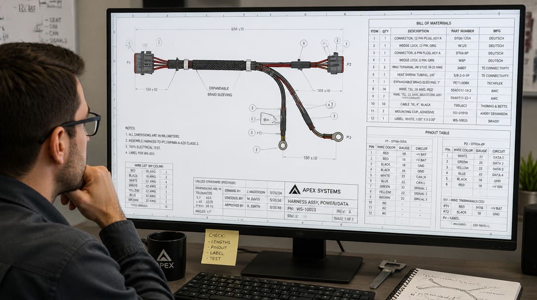
These principles are not abstract best practices — they are the items that, when missed, cause the majority of late‑stage change orders. A harness designed with service loops and standard connectors usually costs less to produce than one that must be re‑tooled because the first‑article sample did not fit the enclosure.
From First Drawing to First Quote: Your Next Step
The path from seeing “wire harness” on a BOM to holding a finished assembly is shorter when the groundwork is laid deliberately. The process can be summarized in a few steps: determine whether the project is a wire harness or a cable assembly, gather the specification checklist (quantity, wire gauge and construction, connector part numbers with plating, color requirements, test expectations), and approach a supplier with a package that answers their most important questions before they ask.
Read the detailed wire harness manufacturing guide for a deeper look at the production standards, quality inspection steps, and export packaging practices that protect orders during global shipment. Robust quality inspection and export packaging processes safeguard the finished harness from crimp damage and moisture during international transit — a critical consideration for OEM buyers who rely on just‑in‑time delivery.
Frequently Asked Questions
What’s the difference between a wire harness and a cable assembly?
A wire harness bundles multiple loose wires to route power and signals inside an enclosure, often with branches and open connectors. A cable assembly typically contains one or more factory‑finished cables with molded environmental protection, used for external interconnects between equipment. The environmental sealing and connector style differ significantly, which affects price.
Why does wire harness cost vary so much with quantity?
Connectors, terminals, and especially custom‑color wire carry manufacturer minimum order quantities. A low‑volume order (e.g., 50 pieces) may absorb the full cost of a minimum reel of wire and a connector lot charge, whereas spreading those fixed costs over 500 or 1,000 units cuts the per‑piece price considerably. Quantity is the single most important input for an accurate quote.
What if I don’t have the exact connector part number?
Provide as much detail as possible: mating connector series, pin count, pitch, gender, and any manufacturer markings visible on the sample. An experienced wire harness supplier can often identify the connector from photos and dimensions, but missing the plating specification will still create uncertainty. If in doubt, share a sample or a clear photograph with a scale reference.
Does the color of the wire really matter?
Yes. Standard colors like red, black, blue, and green are typically available from stock without extra charges. Specific custom colors or two‑color stripe patterns usually require a dye lot run with set‑up costs and longer lead time. Unless the harness must match a legacy color code for safety or compliance reasons, sticking to standard colors reduces cost and simplifies re‑ordering.
What’s the typical lead time for a custom wire harness?
Lead time depends on component availability, order quantity, and the maturity of the documentation. A fully specified harness using standard connectors and wire can often be produced within a few weeks. Introducing custom wire colors, rare connector variants, or incomplete specifications adds weeks to the schedule. Early involvement of the supplier during the design phase helps align lead‑time expectations with production planning.
Key Takeaways
- A wire harness is a structured, documented assembly — not a random bundle of wires — and its design directly impacts manufacturing cost and field reliability.
- Understanding the difference between a wire harness and a cable assembly prevents miscommunication that can delay quotations and lead to incorrect pricing assumptions.
- Quantity, wire specification, connector plating, and color requirements are the four details most frequently overlooked by first‑time buyers, yet they are essential for an accurate quotation.
- Preparing a specification package with AWG sizes, connector part numbers, and test expectations shortens the quote‑to‑production cycle and builds trust with the supplier.
- Design choices such as service loops, standard component selection, and upfront acceptance standards (e.g., IPC/WHMA‑A‑620) lower production risk and avoid late‑stage change orders.