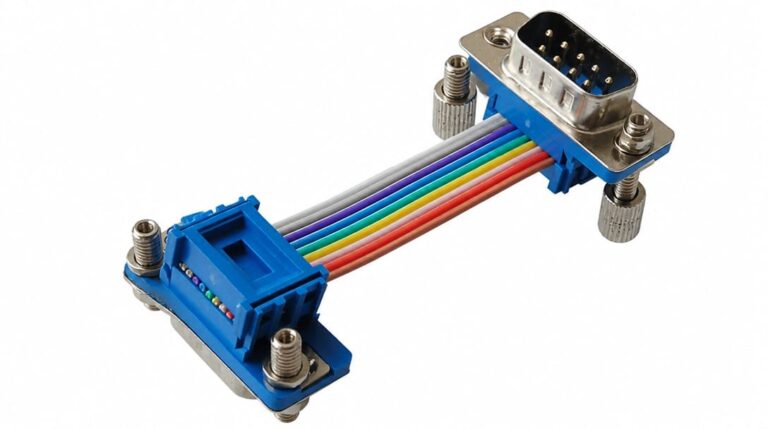
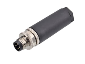
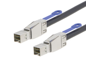
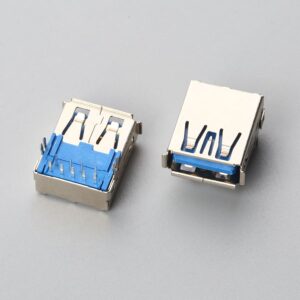
A robust wiring and harness design starts with translating electrical, mechanical, and environmental requirements into a clear design brief. Select wire gauge based on continuous current and voltage drop, not just ampacity charts, and specify connectors that are compatible with production tooling. Route with bend radii, service loops, and clamping in mind, and document every crimp, label, and test point to prevent expensive back-and-forth during manufacturing.
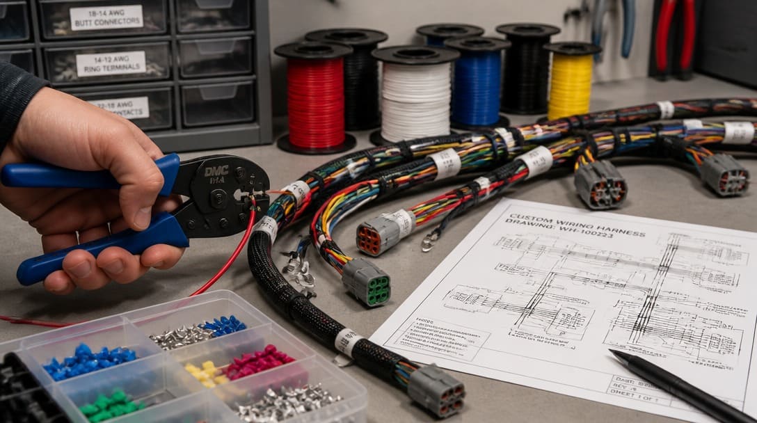
Translating System Requirements into a Harness Design Brief
Before selecting a single component, the designer must extract and organize the fundamental constraints that will govern every downstream choice. A schematic alone is insufficient; it must be combined with the I/O list, mechanical model, and environmental profile. The following steps create the quantitative foundation for a manufacturable harness.
What to Extract from Schematics and I/O Lists
- Pin-to-pin connectivity list: Every signal path, including spare lines, documented with the originating and destination connector cavities.
- Signal classification: Categorize each circuit as power, analog, digital (low-speed), high-speed data, or specialty (CAN, LIN, LVDS). Note voltage levels and whether differential pairs exist.
- Derived currents: For power circuits, list continuous current and any inrush transient values. Apply derating per the acceptance standards in IPC/WHMA-A-620[1] to account for temperature rise in bundled wiring.
- Shielding and isolation requirements: Mark which signals need dedicated shield drain wires, twisted-pair construction, or isolation from power runs.
Reviewing the Mechanical Envelope
The 3D CAD model reveals more than just where connectors mount. It shows:
- Dynamic flex zones: hinges, robot joints, or sliding drawers where the harness must repeatedly bend.
- Clearance bottlenecks: gaps that force specific branch routing or eliminate room for thicker insulation.
- Assembly and service access: can a technician insert the connector by hand during assembly? Is there enough finger clearance?
Decision Table: Electrical Parameter to Design Implication
Mapping each circuit parameter to a wire-level decision prevents over‑engineering or dangerous under‑specification. Use the following table as a starting point, referencing SAE J1128 for automotive wire and UL 758 for appliance wiring.
| Parameter | Typical Value Range | Design Implication |
|---|---|---|
| Continuous current (A) | 0.5 – 30 | Wire gauge (AWG) selection, bundle derating, insulation temperature class |
| Voltage (V) | 12 – 600 | Insulation dielectric strength, creepage and clearance distances |
| Signal frequency / rise time | kHz – MHz | Need for twisted-pair geometry, shield type, characteristic impedance control |
| Operating ambient (°C) | –40 to +125 | Insulation material selection: PVC, XLPE, silicone, or PTFE |
| Flex cycles (lifetime) | < 10,000 to > 1 million | Conductor stranding: solid, stranded, or high-flex fine‑strand (Class M) |
| Chemical/moisture exposure | Oil, fuel, salt spray | Insulation chemical resistance, sealed connectors, cavity plugs |
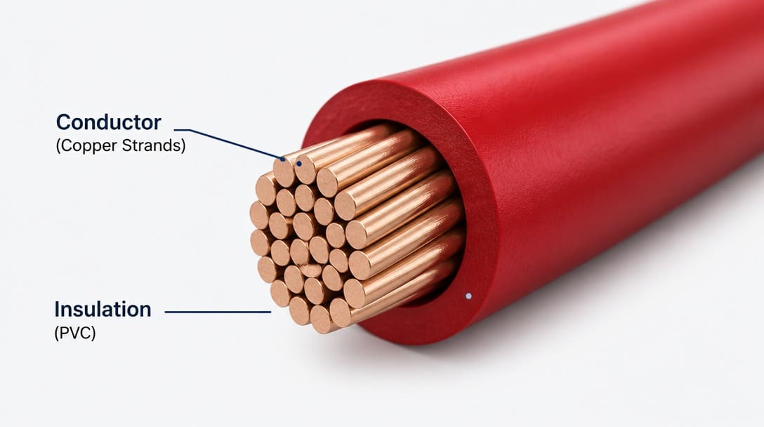
Selecting Wire Gauge, Insulation, and Conductor Type
As outlined in wire harness design principles for reliable OEM cable assemblies, once the circuit currents and environmental conditions are captured, wire selection becomes an exercise in balancing electrical, thermal, and mechanical demands. The process begins with a voltage-drop calculation and considers temperature, bundling, and insulation type.
Continuous Current and Voltage Drop
For a 10 A circuit in a 60°C engine compartment, the effective conductor temperature rise inside a bundle can be significant. Industry derating guidance from SAE J1128 and UL 758 recommends adjusting the free‑air ampacity to account for the number of bundled conductors. The goal is to keep the end‑to‑end voltage drop within the load’s tolerance, often below 3% of the system voltage. A single wire‑gauge step up can recover enough voltage margin to prevent erratic behavior at the far end of a long harness.
Insulation Material Comparison
| Material | Temperature Range | Key Attributes | Typical UL Styles |
|---|---|---|---|
| PVC | –20°C to +105°C | Cost‑effective, good flexibility, limited chemical resistance | UL1007, UL1015 |
| XLPE | –40°C to +125°C | Higher temperature rating, better abrasion resistance than PVC | UL3239, SAE J1128 TXL, GXL |
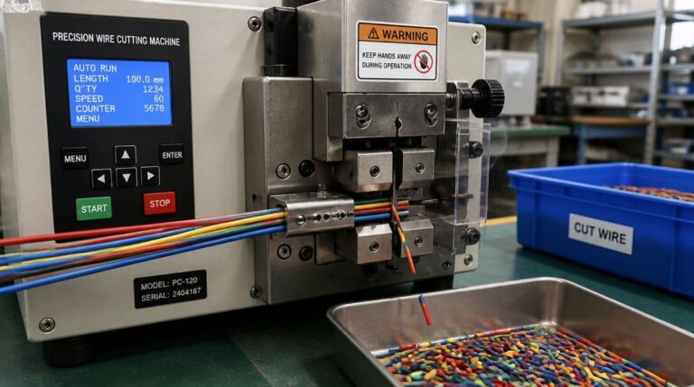
| Silicone | –60°C to +200°C | Extreme flexibility, high heat resistance, soft jacket — can be difficult to feed on automatic cut‑and‑strip machines | UL3122 |
| PTFE | –60°C to +260°C | Excellent chemical and heat resistance, low outgassing, high cost | UL1180 |
In many cases, a higher‑temperature insulation also brings compliance advantages — for example, UL‑recognized styles simplify certification for equipment destined for North America. RoHS‑compliant insulations and lead‑free conductor platings are worth confirming early, as global OEM buyers routinely require full material declarations.
Conductor Type: Solid vs. Stranded vs. Fine‑Strand
Solid conductors are rarely used in dynamic applications. Stranded wire (Class B or C) provides a good balance for routed harnesses with limited flexing. For applications exposed to repeated motion — robotic arms, cable carriers, or hinge‑mounted harnesses — fine‑strand conductors (Class M) are mandatory. A crucial manufacturing reality: extremely soft silicone or ultra‑fine‑strand wire can feed unpredictably on automatic cut‑and‑strip equipment. A design that looks optimal on paper may require dedicated production fixturing or slower processing speeds, directly affecting lead time.
Choosing Connectors and Terminals
Connector selection transcends mating compatibility. The real engineering lies in specifying the electrical, mechanical, and manufacturing interface between the wire and the contact system.
Contact and Terminal Decisions
- Plating durability: Gold over palladium‑nickel ensures low contact resistance across thousands of insertion cycles; tin plating is economical but sensitive to fretting corrosion in vibration environments. Match the plating option to the required mating cycles.
- Retention force per contact: Inline connectors and high‑vibration applications benefit from contacts with high individual retention force, avoiding intermittent disconnects.
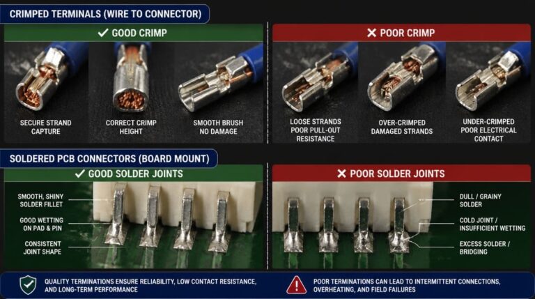
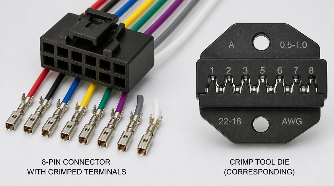
- Crimp terminal selection: Each terminal accepts a specific wire gauge range. Pairing a terminal with a wire just under the maximum barrel capacity can still result in a cold‑weld crimp if the insulation wall thickness is not correct. IPC/WHMA-A-620 defines pull‑force and crimp‑height criteria needed to validate a gas‑tight connection. Without them, a harness that passes simple continuity may fail under thermal cycling.
Tooling Compatibility: The Hidden Schedule Risk
A designer may select a connector from Catalog A, only to find that the ‘equivalent’ connector requires a proprietary crimp tool not already available on the production floor. The result: a special tool order that adds weeks and minimum order charges, delaying the sampling phase. Early validation of tooling — whether standard dies with an existing applicator can accommodate the chosen terminal — prevents costly mid‑project surprises.
Sealing and Environmental Provisions
For IP‑rated connectors, the BOM must explicitly include sealed terminals, cavity plugs for unused positions, grommets, and backshells. Leaving any of these as an afterthought leads to moisture‑ingress failures that manifest only after weeks of field exposure, well beyond prototype testing.
Routing, Branching, and Strain Relief
The mechanical design layer determines whether the harness survives its intended lifecycle. Chafing, fatigue, and pull‑out failures are often purely routing problems, not component defects.
Bend Radius and Clearance
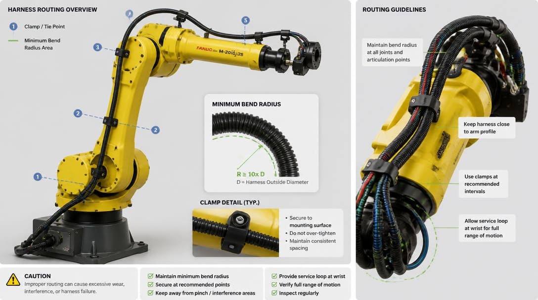
IPC/WHMA-A-620 defines minimum static and dynamic bend radii relative to the wire outer diameter. In practice, this means measuring every elbow in the CAD model, especially at articulated joints and robot arms where dynamic flex adds mechanical strain. Adding a service loop — a small extra length that absorbs thermal expansion and assembly misalignment — is cheap insurance against tension on the connector.
Strain Relief and Clamping
Clamping must spread the load across the harness outer covering, not pinch individual conductors. Grommets, P‑clips, and cobra clips isolate the termination area from mechanical stress. A common mistake: clamping directly on a wire instead of on the braided shield or an integrated strain‑relief boot, which transfers vibration straight into the crimp joint.
Practical Routing Checklist
| Checklist Item | Status |
|---|---|
| No chafing against sharp edges or fastener heads | ☐ |
| Clearance maintained to exhaust manifolds, motors, or other heat sources | ☐ |
| Dynamic flex zones checked against minimum bend radius | ☐ |
| Sufficient finger access for connector lock‑lever operation during assembly | ☐ |
| No interference with moving mechanical parts throughout full range of motion | ☐ |
| Label break‑out points precisely located and oriented for readability during maintenance | ☐ |
| All service loops securely tied but not strained | ☐ |
Design Documentation That Prevents Production Errors
A harness design is only as good as its documentation. When the drawing and BOM fail to convey the exact production intent, phone calls and emails erode the schedule, and traceability gaps open up.
Essential Wire Table Contents
- Wire ID (matching the schematic), color/stripe code, AWG, insulation type, length tolerance.
- From‑to connector reference designator and cavity number, including ground studs and shield terminations.
- Twist and shield instructions: drain wire size, shield termination method, and any jacket strip‑back dimensions.
Label Callouts and Crimp Specifications
Heat‑shrink labels or printed markers must have their text content, placement position, and reading orientation specified. Without this, assembly staff improvises or skips labels, creating configuration control nightmares. For every terminal, the drawing should call out the exact crimp tool, die, pull‑force range, and crimp height. A note that only says “standard crimp” is not a specification — it is a gamble.
Test Points
Designate continuity, hipot, and insulation resistance test points directly on the harness drawing. Include acceptance criteria so that quality assurance can verify results against a known standard. Clear test definitions also support consistent quality inspection and export packaging documentation — a link that many teams overlook until the first shipment audit.
Suppliers such as EDOM Electronics support OEM buyers with requirement review, connector matching, sample coordination, production follow-up, inspection, and export-ready packaging for custom cable assemblies.
To prevent these documentation gaps, many design teams use a structured specification checklist. Download our free wire harness specification checklist.
Common Design Failure Modes
Field failures often trace back to design decisions that seemed reasonable on a desk but ignored real‑world stress factors. The following stories illustrate how even a single oversight can bypass bench testing yet cause costly warranty returns.
Intermittent Opens from Cold‑Weld Crimps
A harness passed continuity at final test but began intermittently dropping a sensor signal after several weeks of thermal cycling. The root cause: a terminal with a slightly oversized wire barrel that never achieved a gas‑tight crimp. As temperatures fluctuated, the contact interface oxidized, creating high‑resistance opens. Continuous crimp‑height monitoring and pull‑force sampling during production, as defined in IPC/WHMA-A-620, would have caught the issue long before the harness shipped.
Insulation Chafing Inside a Robot Arm
A dynamic harness routed inside a six‑axis robot arm had no protective wrap and minimal clearance to an internal casting ridge. After approximately 50,000 flex cycles, the ridge rubbed through the primary insulation, causing a short to a nearby signal wire. A simple PTFE spiral wrap and an additional clamping point at the pivot entrance eliminated the failure without altering the harness layout.
Moisture Ingress in an Outdoor Enclosure
An inline connector pair in an outdoor telecom enclosure was not fully sealed because the cavity plug BOM entry was overlooked. High humidity led to corrosion that formed high‑resistance joints within weeks. The assembly passed initial bench testing because the moisture had not yet penetrated. The lesson: seal every mated pair and explicitly include all environmental provisions in the design BOM.
Excessive Voltage Drop from Undersized Wire
A 5‑meter motor‑circuit harness used a wire gauge calculated from the motor’s nameplate current but ignored the actual run length. The resulting 2 V drop at the motor caused erratic control board resets under load. Upsizing the wire by one AWG step added negligible cost but recovered full system stability.
How Design Choices Impact Manufacturing Cost and Lead Time
Designers rarely see the production floor, but their decisions directly determine how efficiently a harness can be built. Awareness of these connections can turn a technically sound design into a commercially optimized one.
Wire Color Customization
In our experience, a designer who specifies custom‑color wires for every circuit without a functional reason often adds weeks and setup charges that could have been avoided with a simpler scheme using striped standard colors. Reserve custom colors for identification needs that cannot be met with standard offerings, such as specific safety circuits or high‑contrast requirements in poor lighting.
Special Tooling
Connectors that demand proprietary or uncommon crimp tools force minimum order quantities and lead times that ripple through the project schedule. Validate tool availability during the connector selection phase — not after the BOM is frozen — and prefer connector families that can be processed with existing production floor tooling.
Cut Length Tolerances
Specifying ±1 mm on every wire length where ±5 mm is functionally adequate drives up scrap rates and increases inspection time. Apply realistic tolerances aligned with the acceptance class in IPC/WHMA-A-620. This small adjustment dramatically improves first‑pass yield without affecting harness fit.
Branch Complexity
Every break‑out point adds manual assembly labor and fixturing cost. While complex branching is sometimes unavoidable, grouping circuits into a few breakout locations rather than many isolated drops can reduce build time and the risk of routing errors.
A well‑detailed design feed directly into a smoother manufacturing process. Explore the wire harness manufacturing overview to learn how to turn your specification into a repeatable, high‑quality production run. For support with custom cable assemblies that bridge design and manufacturing, explore custom cable assembly solutions.
Frequently Asked Questions
What information do I need to provide to get an accurate harness manufacturing quote?
At minimum, a manufacturer needs a wire table with pin‑to‑pin connectivity, wire gauge and insulation type, connector part numbers and cavity assignments, cut lengths with tolerances, shield termination details, and any labeling or test requirements. Including the mechanical layout drawing and environmental operating conditions allows the supplier to flag routing or insulation issues early.
How do I choose the right wire gauge for my harness?
Start with the continuous circuit current and the acceptable voltage drop for the run length, then apply bundle derating factors from SAE J1128 or UL 758. Verify that the chosen gauge fits the terminal’s wire‑acceptance range and that the insulation temperature class meets the highest ambient in the harness path.
Why does connector tooling compatibility matter so much?
A connector may be electrically perfect, but if the required crimp tool is not already available on the production floor, the project faces extra tooling costs, longer lead times, and potential minimum‑order hurdles. Early verification of tooling compatibility during the design phase prevents schedule disruptions.
What is the most common cause of harness failure in dynamic applications?
Insulation chafing and conductor fatigue at flex points are the most frequent root causes. These failures almost always result from routing that violates the minimum dynamic bend radius, lack of strain relief, or missing protective wraps. IPC/WHMA-A-620 provides acceptance criteria for bend radii and clamping that can be validated against the CAD model.
How can I reduce lead time and cost in harness design without sacrificing reliability?
Use standard wire colors, select connector families with common crimp tooling, apply realistic length tolerances, and consolidate break‑out points where possible — these are key considerations for OEM procurement. Suppliers such as EDOM Electronics can assist with these optimizations to reduce cost and lead time.
Key Takeaways
- Begin with a structured design brief that maps every circuit’s current, voltage, signal type, and environmental condition to wire‑level requirements.
- Select wire gauge, insulation, and conductor type based on voltage drop, ambient temperature, and mechanical flex demands, not a simple ampacity chart.
- Evaluate connectors for plating durability, retention force, and tooling compatibility — not just mating pin‑and‑socket arrangement.
- Enforce bend radii, strain relief, and routing clearances from the 3D CAD model to eliminate chafing and fatigue failures.
- Document every crimp, label, and test point explicitly; incomplete specifications are the primary source of production delays and quality escapes.
- Anticipate the manufacturing impact of color choices, tolerances, and break‑out complexity to keep cost and lead time under control.