At a Glance
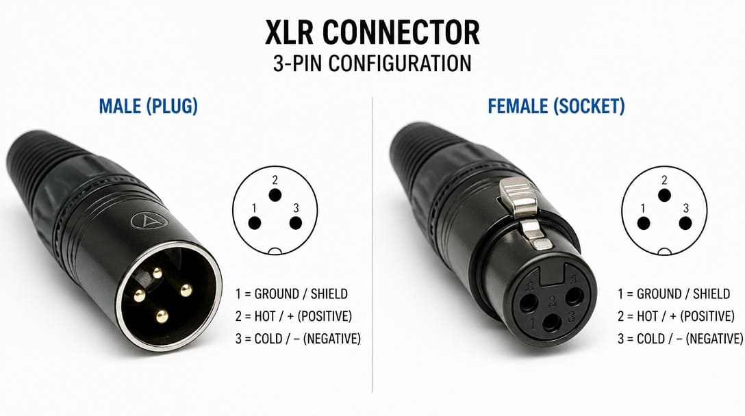
An XLR connector is a circular electrical connector primarily used to transmit balanced analog audio signals between microphones, mixers, amplifiers, and professional audio equipment. Standard XLR connectors typically have three pins, although 4-pin, 5-pin, and higher-pin versions are also available for lighting, intercom, and industrial applications.
Direct Answer: What Is an XLR Connector?
An XLR connector is a cylindrical, multi‑pin interconnect defined by its locking mechanism, pin arrangement, and standardized shell sizes. Originally developed from the Cannon X series designed by James H. Cannon (which subsequently added a Latch and Rubber compound to become the XLR), the term XLR today describes a family of connectors used primarily in professional audio, broadcast, and stage equipment. The 3‑pin type is the most visible, but 4‑pin, 5‑pin, 6‑pin, and 7‑pin variants exist for DC power, intercom, DMX lighting control, and multi‑channel audio.
For OEM engineers and procurement managers, the first trap is assuming that any connector called “XLR” functions identically. A dimensional drawing tells you the shell diameter and pin layout, but it doesn’t reveal contact material, retention force, or environmental sealing.
A dimensional drawing tells you the shell diameter and pin layout, but it doesn’t reveal contact material, retention force, or environmental sealing. To understand how these fundamental specifications impact field reliability across all interconnects, review our core guide on what a connector actually does structurally and electrically.
XLR Connector Name: Brand Series vs. Generic Term — Why It Matters on Your BOM
A bill of material entry that reads “XLR connector” or even a part number like NC3FX is not a full specification. NC3FX is a Neutrik product, but XLR connectors are also manufactured by Amphenol, Switchcraft, and numerous other suppliers. Even when the drawing references a specific brand for form‑fit‑function, procurement teams sometimes treat the “XLR” label as a commodity category and substitute a generic part number.
This is risky because brand‑specific variants can differ in:
- Latch force and travel: A panel‑mount socket from one brand may accept a plug from another, but the locking feel and retention force may differ, leading to intermittent disconnects in equipment subject to vibration.
- Internal pin geometry: The shape and spring‑force of the female contact, or the precise barrel dimensions in crimp‑style connectors, can change insertion resistance and contact normal force.
- Material specifications: Differences in PA66 glass‑fiber‑reinforced housings or brass alloy substrates may not appear on a dimensional outline but influence durability and fire resistance.
When Amphenol, Neutrik, or another brand part number is on a BOM, the first step in cross‑referencing is to obtain the original manufacturer’s data sheet and treat the “XLR” name as a category, not a specification. Only then can a meaningful alternative be validated.
From our experience manufacturing custom cable assemblies, XLR connectors are often specified not by connector brand alone but by cable flexibility, shielding effectiveness, strain relief design, and mating durability.
Visual Breakdown: XLR Internal Construction & Pinout
Watch this 6-minute teardown by George Donaldson (EI7KO) for a quick visual walkthrough of male vs. female XLR design, the Neutrik locking mechanism, and Pin 1/2/3 terminal layout.
OEM Engineering Takeaways:
Strain Relief & Durability: Notice how genuine Neutrik chuck-type strain relief prevents cable fatigue compared to generic screw-clamp alternatives.
Pin 1 Ground Sequence: Correct terminal layout is critical for “First-to-Mate, Last-to-Break” grounding to prevent ESD damage and audio pops during hot-plugging.
Assembly Process Match: Always sample-test internal solder cups and housing heat limits to ensure they fit your specific wire gauge and harness assembly line.
Pro-AV and Stage Integrity: Grounding Sequence, 110-Ohm Digital Impedance, and DMX Standards
Sourcing circular interconnect systems for broadcast consoles and stage lighting racks introduces physical-layer safety and high-frequency design constraints that go beyond basic wiring continuity:
1. Pin 1 “First-to-Mate, Last-to-Break” (FMLB) Grounding Design
In live sound environments, hot-plugging microphone lines is standard practice. If the differential signal contacts (Pin 2 and Pin 3) establish connection before the ground shielding (Pin 1), the system experiences a massive electrical pop that can destroy speaker drivers and cause electrostatic discharge (ESD) damage to sensitive microphone preamplifiers. To prevent this, all compliant female XLR receptacles are engineered with a physical contact offset: Pin 1 is physically longer and positioned closer to the mating face, guaranteeing that the ground path is established first during insertion and broken last during extraction. This grounding sequence is a non-negotiable safety feature for system integrity.
2. AES/EBU 110-Ohm Impedance Matching for Digital Audio
While standard analog XLR connectors and cables carry 3-pin balanced mono signals at arbitrary impedances, digital audio transmission (AES/EBU) demands a strict impedance-matched environment. The AES/EBU digital standard requires a continuous characteristic impedance of 110 Ω. Unlike analog audio signals where cable capacitance is the primary concern, digital audio protocols (AES3 / IEC 60958 / AES/EBU) transmit high-frequency digital pulses requiring a controlled 110 Ω (±20%) characteristic impedance. Transmitting 3.072 MHz AES3 signals through standard analog XLR cables causes severe impedance mismatches. This results in signal reflections, reduced rise times, and clock jitter—ultimately causing bit errors, DAC sync lock failure, and audio dropouts over long cable runs. This mismatch triggers signal reflections, high-frequency phase jitter, and digital dropouts. OEM buyers must specify 110-ohm rated XLR assemblies for any digital routing applications.
3. DMX512 5-Pin XLR Safety Standard
While primary DMX512 communication uses three conductors (Data-, Data+, and Common Ground), the ANSI E1.11 / USITT DMX512-A standard explicitly mandates 5-pin XLR connectors for two main reasons:
- Pin Allocation for Secondary Data Link: Pins 4 and 5 are reserved under ANSI E1.11 for a secondary data link (for bi-directional status monitoring or auxiliary data channels).
- Physical Interoperability Safety: Restricting lighting data to 5-pin XLRs prevents field operators from accidentally plugging low-voltage EIA-485 lighting transceivers into 3-pin Pro-Audio mic inputs with active +48V Phantom Power—or plugging line-level audio outputs into DMX lighting buses, preventing hardware burnout and signal corruption in live staging environments.”
Three Critical Parameters a Datasheet Drawing Won’t Always Surface
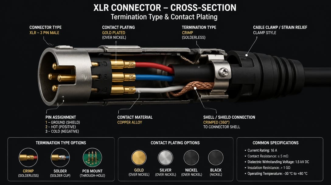
Industrial connector drawings typically show external dimensions, pin layout, and mounting panel cutout. The three most consequential parameters for production reliability are often absent or described only in abbreviated codes:
1. Termination compatibility
A 3‑pin XLR can be solder‑cup, PCB‑pin, or crimp. Each termination method presupposes a specific assembly process. A solder‑cup variant designed for manual soldering at 350 °C works fine, but an alternative with a lower‑temperature thermoplastic housing may deform in a wave‑solder or reflow process. For crimp‑type connectors, the wire barrel diameter range must match the conductor cross‑section and insulation thickness used on the production line. A drawing rarely specifies the full wire gauge range or the exact strip length, yet a mismatch here is a prime cause of field rework.
2. Contact plating material and thickness
XLR contacts are commonly plated with gold, silver, or nickel. Each offers a different balance of contact resistance, corrosion resistance, and insertion lifetime. A gold flash layer of only a few microinches behaves very differently from a 30‑microinch hard‑gold over nickel underplate after 1000 mating cycles. Thickness and underplate composition are invisible on a mechanical drawing but directly govern the connector’s electrical stability and RoHS[1]‑compliant solderability. UL flammability rating of the housing — another hidden parameter — also matters: the material must often meet UL 94 V‑0 for enclosed equipment.
3. Mechanical retention
The latch mechanism that gives XLR its secure feel can vary in detail. Some designs use a stainless‑steel spring clip, others a plastic internal catch. The release button travel, insertion force, and even the thread pitch of the coupling ring may differ between suppliers. In a rack panel or portable equipment that is frequently plugged and unplugged, a slightly different latch geometry can cause disconnection under vibration or wear out the mating socket prematurely. Board‑mount versions may rely on snap‑in pegs or through‑hole anchors whose dimensions affect solder joint reliability — information not always called out on a customer’s 2D drawing.
Compatible vs. Interchangeable: The Costly Confusion in OEM Procurement
When sourcing an alternative XLR connector, the words compatible and interchangeable often get used as if they mean the same thing. In OEM manufacturing, they point to two very different levels of risk.
| Term | Meaning | Risk for Procurement |
|---|---|---|
| Compatible | Two connectors can mate without physical damage. The plug fits the socket, and continuity may be acceptable in static conditions. | Contact resistance may be higher, retention force may be weaker, and long‑term reliability is unknown. Noise or intermittent connection can emerge under vibration or temperature cycling. |
| Interchangeable | The alternative part is functionally identical in form, fit, function, and has been proven through equivalent qualification testing. It can be substituted without process changes. | This is a rare claim for electromechanical components. Even if general dimensions match, subtle differences in plating, spring force, or dielectric materials can alter system performance. |
To move from “compatible” to a defensible claim of interchangeability, procurement teams should request mating‑cycle test data per EIA‑364 or equivalent, along with production‑level environmental test reports. Without this, a self‑declared “XLR compatible” alternative is a liability, not a solution.
| Key Qualification Parameter | Generic ‘Compatible’ Alternative | Verified ‘Interchangeable’ OEM Spec | Relevant Standard / Test Method |
|---|---|---|---|
| Contact Resistance | < 15 mΩ (Initial) | < 5 mΩ (Initial), < 10 mΩ (Post-Test) | EIA-364-23 |
| Mating Durability | Unspecified (~100 cycles) | ≥ 1,000 Mating Cycles | EIA-364-09 |
| Plating Stack-up | Gold Flash (< 3 µin) | 30 µin Gold over 50 µin Nickel | ASTM B488 / Plating Cert |
| Insulation Material | Standard PBT (HDT 180°C) | High-Temp PA9T / LCP (260°C Reflow) | UL 94 V-0 / ISO 75 |
| Salt Spray Corrosion | 24 Hours | 48 / 96 Hours Pass | ASTM B117 / EIA-364-26 |
Production Reality: Where Connectors Fail Before Electrons Flow
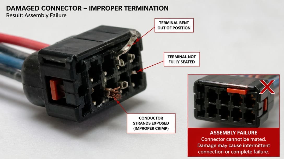
We regularly see connectors that pass visual incoming inspection but fail during assembly — the termination interface or plating stack was engineered for a different process than the one running on the production line. The part looks right; the process doesn’t know it’s wrong.
Consider a solder‑cup XLR specified for manual soldering. The OEM’s harness shop switches to an alternative that uses a higher glass‑transition‑temperature housing, unaware that the original part was validated for a wave‑solder cycle the new part cannot survive. Or a crimp‑type XLR arrives on the line with a wire barrel sized for AWG 20–22, while the harness uses AWG 18 conductors — every termination requires pliers, rework, and inconsistent crimp quality. These failures are not connector defects; they are misalignments between the connector’s design assumptions and the actual assembly environment.
Pre-Order Connector Verification Checklist for Non-Specialist Teams
Before committing to an order, cross‑functional teams should validate these four points — even when the part number looks identical on paper.
| Verification Step | What to Confirm | Why It Matters |
|---|---|---|
| Termination method | Solder‑cup, PCB pin, or crimp matches your assembly process and wire gauge range. For PCB, obtain the actual footprint drawing with tolerance stack‑up. | Prevents soldering process incompatibility, wire gauge mismatches, and unreliability due to poor crimp quality. |
| Plating specification | Request a plating certificate stating material, thickness, and underplate. Compare with mating‑cycle requirement and environmental exposure (RoHS compliance alone is not enough). | Determines contact reliability over the product life; thin plating may fail prematurely in high‑humidity or high‑mating applications. |
| Mechanical retention | Verify latch type, insertion force, extraction force. For board‑mount types, check for board locks, through‑hole anchors, and snap‑fit retention. | A mismatch causes connector loosening, intermittent connections, or solder joint stress. |
| Mating interface sample validation | Obtain physical samples of both connector halves from the proposed alternative and a known‑good original. Perform visual, mechanical, and continuity checks across at least 20 mating cycles. | Datasheet tolerances can be misleading; only samples confirm real‑world fit, insertion feel, and electrical stability. |
If your team is evaluating an XLR connector alternative, request a free connector compatibility review to validate it against your assembly process before committing to tooling or inventory.
Sourcing XLR Connectors from a Drawing: What a Reliable Partner Should Deliver
For OEM buyers and procurement managers in international trade, receiving a simple price quote for “XLR male, 3‑pin” misses the real value of a capable source. A supplier who understands manufacturing outcomes will review the drawing or BOM for termination style, plating code, and latch variant. They propose exact equivalents or verified cross‑references — not just generic “XLR” substitutions.
Suppliers such as EDOM Electronics support OEM buyers with requirement review, connector matching, sample coordination, production follow-up, inspection, and export-ready packaging for custom cable assemblies and wire harnesses. When connectors are part of a larger interconnect project, a partner with experience in wire harness manufacturing and custom cable assembly can validate termination as a complete system, not a standalone component. Export-ready quality inspection and export packaging ensures connectors arrive undamaged, with carton labeling, batch traceability, and the necessary RoHS documentation.
Next Steps: From XLR to Your Full Interconnect BOM
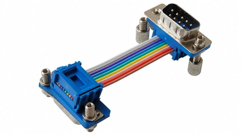
The discipline of verifying termination, plating, retention, and sample mating doesn’t stop with XLR connectors. A single industrial or professional audio BOM often lists Molex wire‑to‑board headers, D‑sub connectors, RJ45 jacks, and USB connectors. Each demands the same level of scrutiny to avoid field failures.
Apply the same verification logic — consider plating, termination, and mechanical retention as part of a cross‑functional review — to every connector line item. For a deeper dive into managing multi‑connector procurement and avoiding BOM risk, explore the electronic connectors resource center.
Frequently Asked Questions
Can I replace a Neutrik XLR with any generic XLR connector?
Not without validation. While many XLR connectors are physically compatible (they mate without damage), contact resistance, latch retention, and housing material may differ. An alternative may work initially but fail under vibration or temperature cycling. Always verify the original manufacturer’s specifications before substituting.
What’s the difference between 3‑pin and 5‑pin XLR?
3‑pin XLR is the standard for balanced mono audio. 5‑pin XLR is commonly used for stereo balanced audio, DMX lighting control, or dual‑channel intercom. The physical connector shell is slightly larger, and the extra pins carry additional signals or power. They are not interchangeable with 3‑pin systems.
Do XLR connectors carry power?
Yes, in some applications. While 3‑pin XLR is typically for audio signals, 4‑pin XLR connectors are often used for DC power (e.g., intercom systems, broadcast cameras). Never assume a connector labeled “XLR” is signal‑only — check the equipment schematic for the voltage and current rating.
How important is gold plating for XLR contacts?
Gold plating significantly improves contact reliability in environments where low signal levels and minimal contact resistance are critical — such as microphone or line‑level audio. It also prevents oxidation and ensures stable performance over many mating cycles. However, the thickness of the gold layer matters: a thin flash layer may wear off quickly. For high‑cycle applications, specify a minimum gold thickness over a nickel underplate and verify with a plating certificate.
What does “compatible” mean when sourcing XLR connectors?
“Compatible” usually indicates that two connectors can physically mate, but it does not guarantee equivalent electrical or mechanical performance. It is a low bar. OEM buyers should insist on “interchangeable” only after verifying termination, plating, and retention characteristics match the original part across all relevant test conditions, including mate/demate cycling per EIA‑364.
Key Takeaways
- An XLR connector is defined by more than pin count and shell dimensions — termination style, contact plating, and latch geometry are the real arbiters of production success.
- Brand‑specific part numbers like Neutrik NC3FX imply detailed design choices; treating “XLR” as a generic category without further verification invites assembly‑line failures.
- Compatible ≠ interchangeable. A connector that mates does not automatically deliver the original part’s electrical and mechanical reliability over the product’s life.
- Pre‑order verification must include termination and plating confirmation, mechanical retention checks, and physical sample validation with the actual assembly process in mind.
- The same rigorous connector evaluation approach should be extended across the entire BOM — including connectors from Molex, TE Connectivity, JST, and Hirose — to avoid cumulative process risk.
For a broader perspective on managing multi‑connector procurement and avoiding sourcing pitfalls, visit the electronic connectors resource center. For specific connector types like insulation piercing connectors, see our insulation piercing connector FAQ.