When a hard drive stops responding, the SATA connector is rarely the first suspect. But in high-vibration server racks or budget build runs, it’s often the last thing engineers check — and the root cause.
OEM Procurement Context: SATA vs. NVMe
While NVMe dominates modern high-performance enterprise storage, SATA connectors remain a massive part of industrial and OEM procurement BOMs. The reason is simple: cost-efficiency for warm/cold data and legacy compatibility. For industrial PCs (IPCs), budget server builds, and high-capacity storage arrays, SATA SSDs and HDDs offer an unbeatable cost-per-gigabyte. Understanding the physical SATA interface is still critical to preventing field failures in these specific, high-volume applications.
At a Glance
A SATA (Serial ATA) connector is the physical interface used for data transfer and power delivery in storage devices such as HDDs, SSDs, and optical drives. The connector family includes a 7-pin data segment, a 15-pin power segment, and combined data+power variants, along with slimline and micro SATA form factors, all governed by the SATA-IO specification. While three speed generations (1.5, 3, and 6 Gbps) do not change the physical connector shape, they impose stricter signal integrity requirements that make specification choices critical for reliable operation.
SATA Connector Family: Pinouts, Keying, and Variants
| Connector Type | Data Pins | Power Pins | Typical OEM Application |
|---|---|---|---|
| Standard SATA | 7 | 15 | 3.5″ HDDs, 2.5″ SSDs, standard server/desktop storage. |
| Slimline SATA | 7 | 6 | Optical drives in legacy laptops or compact rackmount servers. |
| Micro SATA (uSATA) | 7 | 9 | 1.8″ HDDs/SSDs (Older industrial equipment and specific embedded systems). |
Note: Do not confuse Micro SATA with mSATA, which uses a completely different physical form factor (PCIe Mini Card layout).
OEM procurement teams and design engineers frequently encounter SATA connectors on BOMs, device manuals, and legacy equipment diagrams. Identifying the exact variant—not just “SATA connector”—is the first step toward correct sourcing.
The 7-pin data segment carries two differential signal pairs and three ground contacts. A latching mechanism on many cable assemblies prevents accidental disconnection, which is essential in hot-swap backplanes. The 15-pin power segment supplies 3.3 V, 5 V, and 12 V rails, with staggered spin-up and pre-charge pins to manage current inrush. A missing 3.3 V on the power connector can prevent a modern SSD from powering on, a subtle incompatibility that is not obvious from a quick visual inspection.
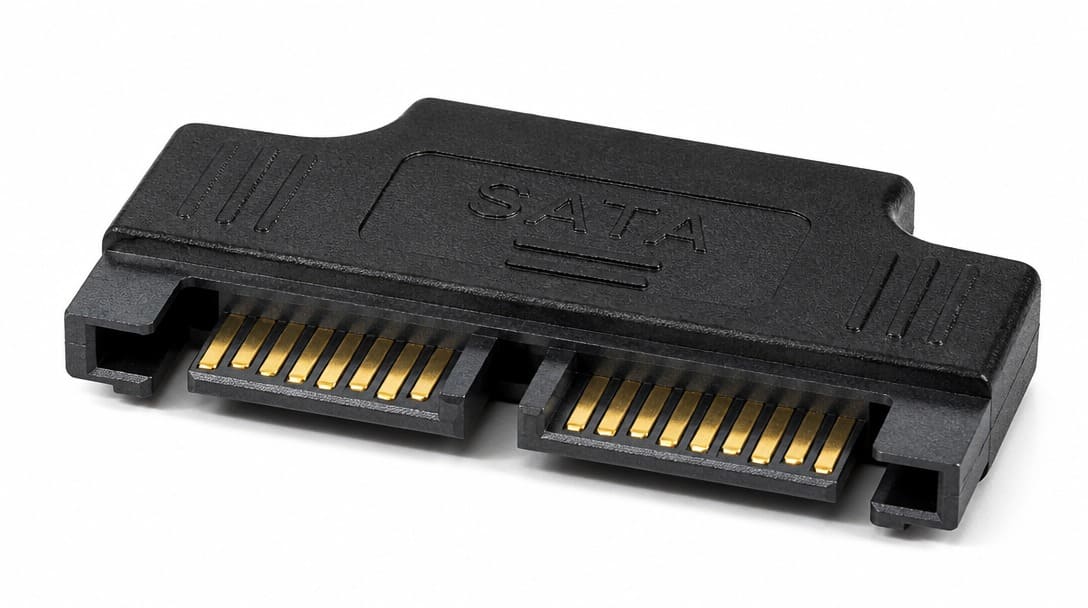
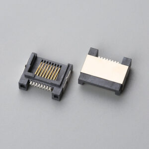
Combination connectors integrate both data and power into a single housing, frequently seen on backplanes and hot-swap drive cages. Slimline SATA, used for slim optical drives, reduces the form factor and uses a 6-pin data+power layout with specific keying. Micro SATA, designed for 1.8-inch drives, employs an 8-pin data+power connector that is physically different from mSATA, a common point of confusion. Connector keying prevents mating a data connector into a power slot, though field reports of forced insertion highlight the need for clear labeling and orientation training.
Beyond Physical Dimensions: The Hidden Specs That Determine Reliability
Two SATA connectors that share identical physical footprints can perform very differently once installed. The root cause lies in specifications that do not appear on a mechanical drawing.
Contact plating is one of the most consequential choices. Gold flash plating (typically 25–50 mating cycles) may suffice for fixed internal cabling, while 30µ” hard gold (500+ cycles) is necessary for hot-swap bays, test fixtures, and environments with frequent reconfiguration. These durability values are validated through EIA-364[1]-09 test procedures. Reputable manufacturers such as Molex, TE Connectivity, JST, Amphenol, and Hirose offer SATA connector lines with clearly documented plating stacks and cycle ratings.
In the power connector, wire gauge directly influences voltage drop. An 18 AWG power cable maintains tighter regulation than a 20 AWG equivalent under load, especially important when multiple drives share a single power rail. Even if the connector fits mechanically, the absence of the 3.3 V rail—mandatory for many current-generation SSDs—will result in a drive that cannot power up. Similarly, cable impedance must stay within 100 Ω ±10% for 6 Gbps SATA III links. Impedance mismatches generate signal reflections that can cause bit errors that intermittent validation tests may miss.
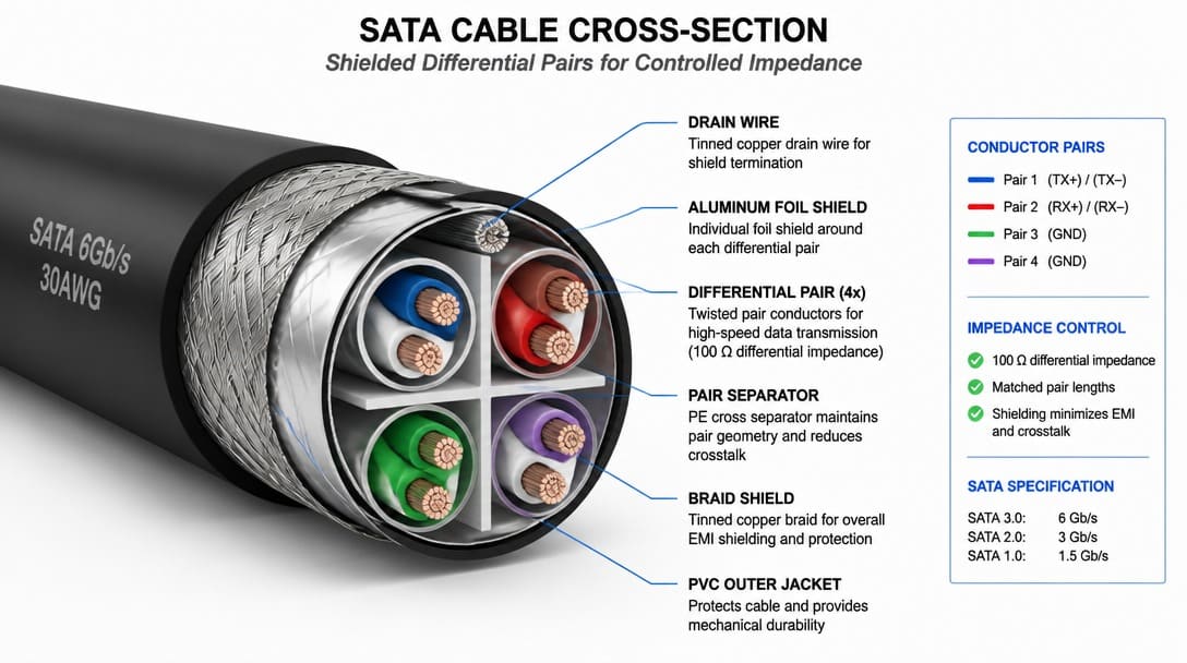
Insert retention force and terminal design are further indicators of field reliability. High-retention contacts from the same established connector manufacturers resist micro-motion wear in vibration-prone server racks, preventing the slow degradation of contact resistance that eventually manifests as CRC errors. Housing material choice—LCP versus standard nylon—also affects durability and flammability rating.
Interchangeable vs. Compatible: Common SATA Assumptions That Backfire
A SATA III cable will physically fit a SATA I host port, but the host’s receive equalization may be unable to compensate for the cable’s higher-frequency characteristics, leading to signal reflections that degrade the link margin. This is a classic example of physical fit masquerading as electrical compatibility. Similarly, a 15-pin power plug that omits the 3.3 V pin may connect to a modern SSD without issue mechanically, yet the drive remains unpowered—a frequent head-scratcher during first-article testing.
Slimline-to-standard SATA power adapters introduce another layer of risk. If the adapter’s pinout does not align with SATA-IO requirements, voltage rails can be misrouted, potentially damaging drives. Data and power connectors are keyed to prevent interchange, but forced insertion in the field still occurs. Educating assembly teams on keying orientation and the distinction between connector families reduces damage and rework.
What Goes Wrong in the Field: SATA Connector Failure Patterns
We regularly see SATA connectors that pass visual inspection but fail in the field — the data contacts have 30-mating-cycle gold flash instead of 500-cycle hard gold, and the storage system doesn’t care that the connector “looks right.” The following failure patterns are common enough to warrant explicit design and procurement attention.
- Intermittent CRC errors from loose contacts. Micro-motion in high-vibration environments wears thin gold flash plating, raising contact resistance. The storage host responds with repeated retries, ballooning I/O latency and eventually logging UDMA CRC errors.
- Power droop from undersized power wires. A multimeter reading open-circuit voltage appears normal, but under load the voltage at the drive drops. This can trigger unexpected resets that corrupt write operations.
- Crosstalk from unshielded parallel routing. When SATA data pairs are bundled tightly without shielding, adjacent pairs couple noise into the signal path, degrading the signal-to-noise ratio at 6 Gbps and causing marginal link training.
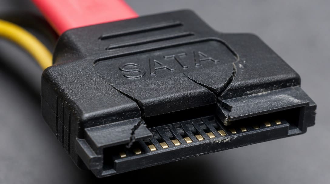
- Connector housing cracking. Repeated mating with housings made from lower-grade materials results in loss of retention and eventual disconnection, especially in chassis with tight cable management.
SATA Connector Verification Checklist for Procurement and Engineering Teams
Before approving a SATA connector for production, the following checks can prevent field failures and avoid costly retrofits:
- Confirm connector type and keying against SATA-IO reference drawings for the exact variant (data, power, combo, slimline, micro SATA).
- Check the plating specification: gold flash for low-cycle applications, 30µ” hard gold for duty cycles above 50; request EIA-364-09 durability test reports.
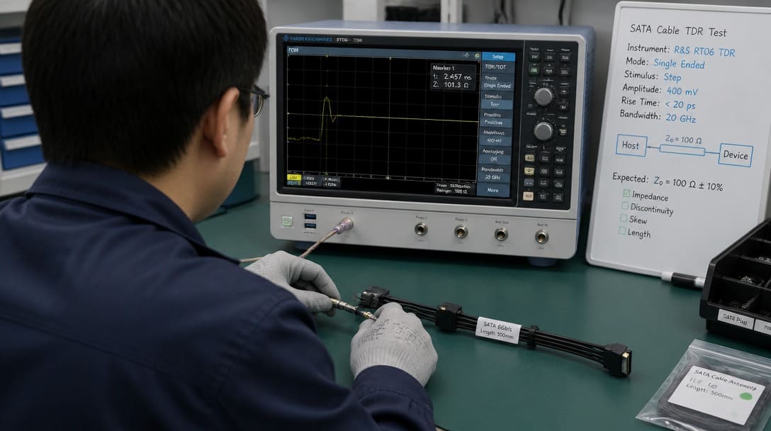
- Measure cable impedance (100 Ω ±10%) and insertion loss for SATA III 6 Gbps links; request time-domain reflectometry data for assembled cables.
- Verify power pin voltage rails with a multimeter under load; ensure 3.3 V is present when the target SSD requires it.
- Perform 50 insertion cycles on a sample batch and re-test contact resistance and signal eye diagram.
- Inspect wire gauge, crimp quality, and pull-force values against the cable assembly drawing.
- Confirm RoHS compliance and UL flammability rating for the connector housing; cross-check certificates against the exact part number.
For team support in connector matching, sample confirmation, or production-grade custom cable assemblies, reach out to EDOM’s engineering coordination team.
Sourcing SATA Connectors for OEM Production: Quality and Compliance Considerations
OEM buyers managing global supply chains must verify more than form and fit. RoHS compliance is non-negotiable for most international markets, and the certificate must apply to the specific part number being shipped. UL recognition gives confidence that the connector meets safety requirements for end-product certification in North America.
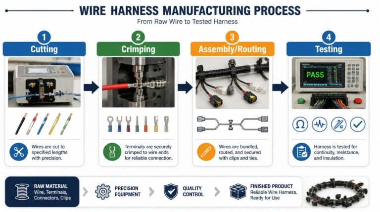
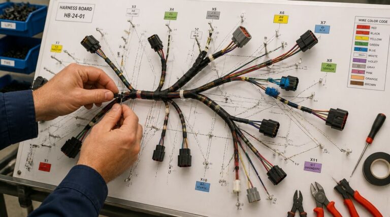
Beyond regulatory marks, full EIA-364 test data—covering contact resistance, durability, insulation resistance, and vibration—should be part of the qualification package. In wire harness manufacturing, SATA power connectors are often integrated into larger wire harnesses, where crimp consistency and routing discipline directly affect system reliability.
Export packaging deserves careful attention. Sensitive SATA connector contacts are vulnerable to deformation and ESD damage during international transit. Dedicated trays, desiccant, and sealed antistatic bags are standard for production-grade SATA assemblies. Suppliers such as EDOM Electronics support OEM buyers with requirement review, connector matching, sample coordination, production follow-up, quality inspection and export packaging, and shipment preparation—providing a single point of coordination from first drawing to delivery.
Beyond SATA: Building Your Connector Knowledge Base
This deep-dive into SATA connectors is part of a broader resource hub. The foundational pillar “What is a connector” covers fundamental selection criteria, material choices, and sourcing strategies that apply across all connector types.
Frequently Asked Questions
Are SATA data and power connectors interchangeable between generations?
Physically, a SATA I, II, or III connector uses the same form factor and keying. Electrically, a SATA III cable may not function reliably in a SATA I host due to impedance and equalization differences. Compatibility must be verified at the signal integrity level, not just by physical fit.
Why does my SSD not power on even though the SATA power connector is plugged in?
Many modern SSDs require the 3.3 V rail on the 15-pin power connector. If the power supply or adapter cable omits this pin, the drive will not initialize. Always check the presence of 3.3 V under load before assuming a connector is compatible.
What plating type should I specify for a hot-swap SATA connector?
For hot-swap applications where connectors experience frequent mating cycles, specify 30µ” hard gold plating over nickel. This provides 500+ reliable cycles, compared to 25–50 cycles for gold flash. Request EIA-364-09 durability verification from the supplier.
How can I verify SATA cable impedance for 6 Gbps links?
Request time-domain reflectometry (TDR) test reports showing differential impedance of 100 Ω ±10% across the cable length. For assembled cables, insertion loss measurements up to 3 GHz should also be provided.
Key Takeaways
- SATA connector selection demands more than matching the physical footprint; pinout, keying, and the specific variant (data, power, combo, slimline, micro SATA) must be confirmed against SATA-IO reference drawings.
- Hidden specifications such as contact plating thickness, cable impedance tolerance, and power wire gauge directly determine reliability in the field, especially at 6 Gbps and in vibration-prone environments.
- A verification checklist that includes plating durability (EIA-364-09), impedance testing, 3.3 V rail verification, and sample insertion cycling prevents costlier failures after deployment.
- Supplier selection for OEM production should require full EIA-364 test data, RoHS compliance, and UL-recognized housings, along with export packaging that protects contacts from ESD and deformation.
For engineering teams evaluating connector options beyond SATA, explore electronic connector sourcing and qualification support.