Direct answer: M8 connector coding is a mechanical keying and pin assignment system defined by IEC 61076-2-104[1] that separates M8 A-coded sensor/DC connectors, M8 B-coded fieldbus connectors, and M8 D-coded Industrial Ethernet connectors to prevent mismating and signal-specific pinout errors in industrial automation systems.
At a Glance
M8 A-coded carries sensor/IO-Link and DC power signals; M8 B-coded follows compact fieldbus assignments (such as legacy PROFIBUS-style or 5-pin fieldbus drops — see our CAN Bus Connector FAQ for related industrial bus wiring rules); and M8 D-coded is engineered for 100 Mbit/s Industrial Ethernet. For OEM engineers and procurement teams, specifying only “M8 4-pin” without a coding letter is a bill-of-materials risk: two connectors can thread together and pass DC continuity testing, yet fail in the field due to swapped data pairs, impedance mismatch, or missing 360-degree EMI shielding.
Picture a design engineer pulling a replacement M8 cable for a new sensor or fieldbus node after a field failure report shows intermittent signal loss. At the same time, a production engineer is on the line trying to mate two M8 connectors from different suppliers, and exactly the problem appears: thread-fit does not equal pin-compatible. Do either of these situations sound familiar?
For industrial automation OEMs, the M8 coding letter determines whether the connector carries sensor/IO-Link signals, Industrial Ethernet data, or DC power. Treating the coding letter as a decoration — rather than as the core mating specification — is the fastest route to returned assemblies, intermittent fieldbus faults, and field replacements that look identical on paper but behave differently under load.
How to Compare M8 Connector Coding: A, B, D
Step 1: Decide the M8 Signal Type First
Start with the electrical function, not the thread size. The M8 coding letter under IEC 61076-2-104 is tied to a specific keyway geometry and pin assignment, which means each coding letter is a functional specification for the signals the connector is designed to carry.
- Discrete sensors, actuators, and IO-Link nodes typically belong on M8 A-coded connectors, which support DC sensor signals and IO-Link style communication.
- PROFIBUS-style fieldbus drops and legacy fieldbus assignments belong on M8 B-coded connectors, where the pinout follows the fieldbus convention rather than a simple DC or data-pair scheme.
- Industrial Ethernet at 100 Mbit/s belongs on M8 D-coded connectors, where the keyway and pinout place the transmit and receive data pairs on the correct contacts.
If the drawing begins with “M8 4-pin male” and nothing else, the signal type and high-frequency transmission parameters have not been specified. While an unshielded A-coded cable only needs to maintain low contact resistance for 24 V DC switching, an M8 D-coded Industrial Ethernet assembly must maintain 100 Ω ± 15 Ω characteristic impedance, twisted-pair symmetry (Tx+/Tx− and Rx+/Rx−), and 360-degree shield termination to the metal coupling nut to prevent EMI-induced packet loss.
Step 2: Compare A, B, and D Coding Against IEC 61076-2-104
IEC 61076-2-104 governs M8 circular connectors for industrial use. The standard ties each coding letter to a distinct keyway geometry and pin assignment, so the coding letter is not a supplier preference or a label color; it is the physical and electrical compatibility gate.
The most decision-critical difference between the three letters is this: M8 A-coded is used for sensor/DC/IO-Link style signals, M8 B-coded is used for fieldbus/PROFIBUS-style assignments, and M8 D-coded is used for Industrial Ethernet data pairs. A mechanically accepted but wrong-coded M8 can pass continuity and still drop packets because the data pairs land on different pins.
| Coding Letter | Keyway Position | Typical Pin Count | Typical Signal | Mate-with Application |
|---|---|---|---|---|
| M8 A-coded | Keyway geometry per IEC 61076-2-104 for sensor/DC use | 3 or 4 pins | Sensor/IO-Link signals, DC power | Discrete sensors, actuators, IO-Link nodes |
| M8 B-coded | Distinct keyway geometry for fieldbus use | 4 or 5 pins | PROFIBUS-style fieldbus assignments | Fieldbus drops, legacy fieldbus nodes |
| M8 D-coded | Distinct keyway geometry for Industrial Ethernet use | 4 pins | Industrial Ethernet 100 Mbit/s data pairs | PROFINET, EtherNet/IP, Modbus TCP nodes |
Save this table as a go/no-go reference. A versus B versus D coding decisions recur across sensor, fieldbus, and Ethernet BOMs, and matching the signal type to the coding letter is the step that prevents most downstream mating failures.
Step 3: Verify Pin Count and Current per Pin
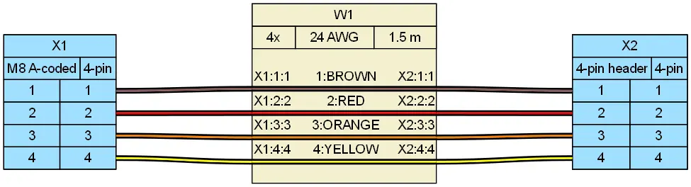
M8 connectors are available in different pin counts, and the coding letter narrows the compatible pin count and signal arrangement. Before finalizing a drawing or approving a sample, verify current per pin against the contact tables in IEC 61076-2-104 or the connector supplier’s tested rating — not a generic catalog value.
Two “M8 4-pin” assemblies can use entirely different pinouts if the coding letter was omitted from the drawing, especially across A, B, and D variants. The same number of positions does not mean the same assignment.
Sealing is another point that must be verified as a mated system. An IP67 rating under IEC 60529[2] indicates dust-tight protection and resistance to temporary water immersion, but the rating applies to the mated pair — not to a single connector body inspected alone. Confirm the connector, the mating half, and the cable entry all contribute to the IP67 condition before signing off.
Step 4: Specify Keying Position and Mating Part Number on the Drawing
Keying position is the physical geometry controlled by the coding letter under IEC 61076-2-104. That is why “M8 4-pin” without the coding letter is not enough to guarantee compatibility. A drawing that specifies only “M8 4-pin male” can result in an A-coded shell with a B-coded pinout because the supplier matched the shell marking, not the signal table.
On the BOM and assembly drawing, list the following as a minimum:
- Signal type (sensor/IO-Link, fieldbus, or Industrial Ethernet)
- Coding letter (A, B, or D)
- Pin count
- Current per pin and voltage class
- Actual mating connector part number from the other side of the interface
PROFIBUS and Industrial Ethernet applications benefit most from this discipline. The D-coded keyway physically prevents accidental mating with an A-coded sensor connector, but only if the coding letter appears on the drawing. When the coding letter is absent, the mistake transfers to the supplier and returns to the project as a field-failure BOM.
Step 5: Run Supplier Mating and Termination Verification
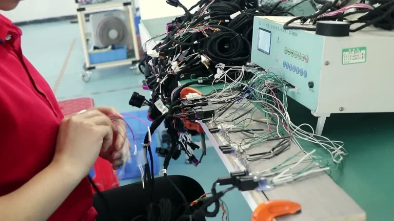
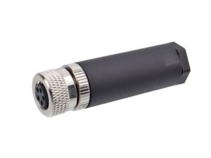
For export-focused OEM and distributor programs, the supplier should review drawings, samples, specifications, target applications, packaging, and delivery expectations before production. For M8 cable assemblies, such as the M8 3-pin female sensor cable assembly, the verification list includes connector matching, cable structure, pinout table, crimping or termination process, continuity testing, appearance inspection, and final verification before shipment.
Require a sample confirmation with both mating halves, not just the M8 connector alone. Keying and pin assignments must be validated as a mated pair; a single-ended sample cannot prove that the assembly will mate correctly at the interface. Suppliers such as EDOM Electronics support OEM buyers with requirement review, connector matching, sample coordination, production follow-up, inspection, and export-ready packaging for custom cable assemblies and wire harnesses.
Export packaging warrants the same attention. Connector shells, terminals, and cable entry points must be protected during international shipping and warehouse receiving. Packaging that compresses, bends, or deforms the M8 keyway can create the same symptom as a wrong-coding part: a connector that threads on but no longer mates electrically. Quality inspection and export packaging work together as the final gate before shipment.
What Goes Wrong in the Field
Forced mismating. When a connector is modified, filed, or forced, the keyway no longer protects the pinout. The operator may hear or feel a latch, but the contact positions may no longer align to the intended signal assignment. Continuity testing can pass while the system-level protocol cannot establish a stable link.
A-coded sensor lines used for Ethernet. An A-coded M8 connector may physically fit a non-standard arrangement, but the Industrial Ethernet data pairs land on the wrong pins. The result is intermittent packet loss, often blamed on noise or firmware. The actual defect is a coding-to-pinout mismatch that never showed up as a dead circuit.
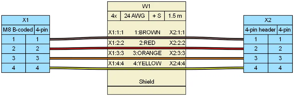
B/D mix-ups. A B-coded or D-coded mix-up can latch mechanically while pin 1 carries power instead of data. The system may energize the wrong contact, damage a transceiver, or create a field failure that continuity testing cannot catch. Returned M8 assemblies in these scenarios often show an A-coded shell with a B-coded pinout because the drawing specified only “M8 4-pin male.” That is a documentation defect, not simply a wiring error.
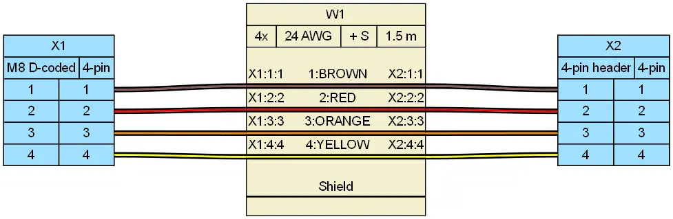
Before You Lock the BOM: A Four-Point M8 Coding Go/No-Go
Run this four-point check before releasing the BOM or approving the sample:
- Signal type: Is this a sensor/IO-Link circuit, a fieldbus assignment, or Industrial Ethernet?
- Coding letter: Does the M8 connector carry the correct A, B, or D code for that signal class?
- Pin count and current per pin: Does the pin count match the coding letter, and does the current per pin fall within the supplier’s tested rating or the applicable IEC 61076-2-104 contact table limits?
- Actual mating connector part number: Was the mating half specified and verified as the mated pair, not just the thread size?
Do not rely on thread size or latch feel alone. Use the coding letter and keying position as the mechanical and electrical compatibility gate. Document the coding letter in drawings, RFQs, and sample confirmations so suppliers, distributors, and assemblers use the same pinout reference. The cheapest M8 cable is not the one that fits the thread; it is the one that survives signal-level verification without intermittent fieldbus faults.
Frequently Asked Questions
What is the difference between M8 A-coded, B-coded, and D-coded connectors?
M8 A-coded is designed for sensor/IO-Link and DC power signals; M8 B-coded follows PROFIBUS-style fieldbus assignments; and M8 D-coded is engineered for 100 Mbit/s Industrial Ethernet data pairs. Each coding letter has a distinct keyway geometry and pin assignment under IEC 61076-2-104.
Can an M8 D-coded connector mate with an M8 A-coded connector?
No, not in a standards-compliant system. The coding keyways are different by design under IEC 61076-2-104 to prevent mismating. If a connector is forced or modified, the keyway no longer protects the pinout and the system may fail intermittently or damage equipment even though continuity testing passes.
Is specifying “M8 4-pin” enough for a cable assembly drawing?
No. The coding letter, signal type, current per pin, and actual mating connector part number must also be specified. An M8 4-pin drawing without the coding letter can result in an A-coded shell with a B-coded pinout because the supplier matched the shell marking, not the signal table.
How can a supplier help verify M8 coding compatibility?
A supplier that reviews drawings, datasheets, and mating halves can flag coding mismatches before sample production. Suppliers such as EDOM Electronics support OEM buyers with requirement review, connector matching, sample coordination, production follow-up, inspection, and export-ready packaging for custom cable assemblies and wire harnesses.
Does IP67 apply to a single M8 connector or to the mated pair?
IP67 under IEC 60529 indicates dust-tight protection and resistance to temporary water immersion, but the rating applies to the mated pair. Confirm the connector, the mating half, and the cable entry all contribute to the sealed condition before signing off.
Key Takeaways
- M8 coding is a functional specification under IEC 61076-2-104, not a cosmetic label — the coding letter controls keyway geometry and pin assignment.
- M8 A-coded carries sensor/IO-Link and DC power; M8 B-coded carries PROFIBUS-style fieldbus assignments; M8 D-coded carries 100 Mbit/s Industrial Ethernet.
- Specify the signal type, coding letter, pin count, current per pin, and mating connector part number on every drawing and RFQ.
- A wrong-coded M8 assembly can pass continuity testing and still drop packets or damage transceivers under load.
- Validate M8 compatibility as a mated pair during sample confirmation, then protect the keyway and cable entry during export packaging.
For OEM programs that route multiple M8 interface types through a single production pipeline, consider engaging a supplier that can review the full mating specification across the BOM. Learn more about wire harness OEM services that support coding verification, sample coordination, inspection, and export-ready delivery.