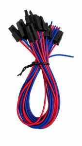
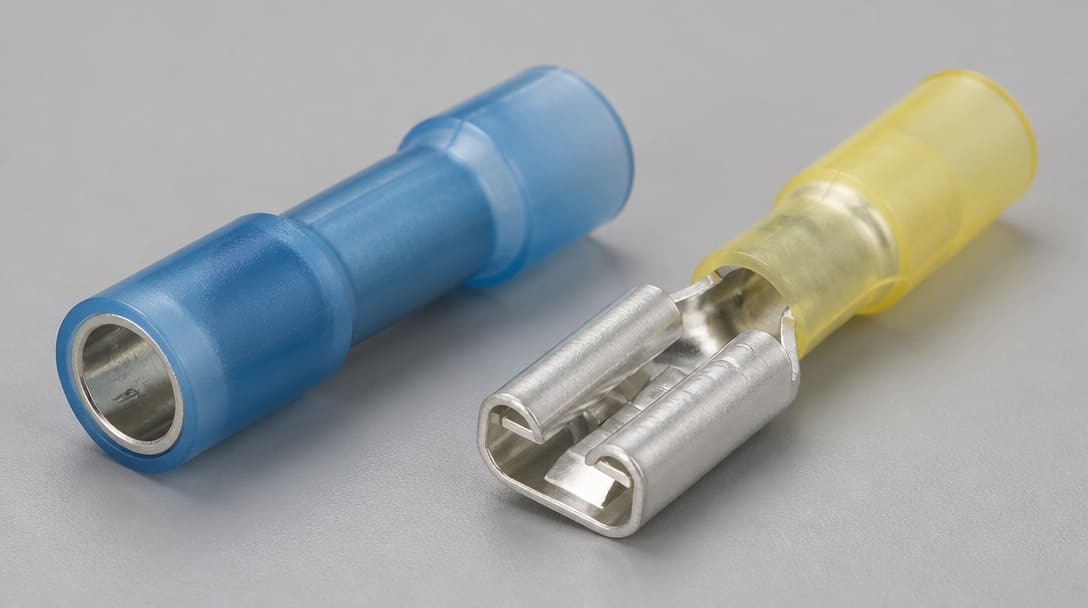
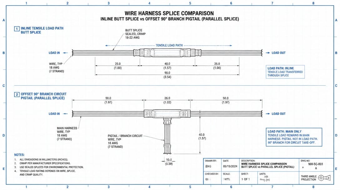
A butt splice connector is an inline insulated crimp terminal with a tin-plated copper barrel that joins two conductors end-to-end for tensile load paths, while a parallel splice connector folds two conductors into a side-by-side tap configuration for branch circuits and pigtails that are not primary pull points.
A supplier BOM on your desk lists both butt splice and parallel splice part numbers. The harness routing drawing does not specify splice orientation, load path, or branch tap location. Approval risk sits right there: if the wrong splice type is signed off for the wrong mechanical condition, field failures show up later as intermittent opens under vibration or hot spots inside a tight conduit. This guide moves the decision away from part-number guessing and into a repeatable, evidence-based approval process.
How to Approve Butt Splice vs Parallel Splice in a Wire Harness BOM
Step 1: Classify Every Splice Line by Load Path and Tap Point
Start by separating each BOM splice line into one of two mechanical functions: an inline tensile connection or a branch tap. A butt splice connector carries linear pull through a continuous tin-plated copper barrel, keeping conductor strands aligned along a single straight axis. In contrast, a parallel splice connector accommodates two or more conductors running side-by-side through the barrel (or in a lap configuration), making it ideal for non-tensile branch taps and pigtails. Before comparing crimp styles or wire gauge AWG, confirm the routing drawing identifies every splice point as either a pull point or a tap point. If the drawing does not show that distinction, request a marked-up harness layout before proceeding.
For OEM buyers coordinating custom cable assembly or wire harness manufacturing, as covered in What Is a Cable Assembly? Definition, Components, and Applications, this classification step is the first gate. A supplier that cannot state the load path for each splice line is not ready for sample approval.
Step 2: Run the Go/No-Go Decision Table for Butt vs Parallel Splice
Use the table below as a desk-level filter. Each row ties a splice type to a specific harness condition. Approve only the splice type that satisfies all rows for that line item.
| Approval Criterion | Butt Splice Connector | Parallel Splice Connector |
|---|---|---|
| Load path | Approve for inline tensile runs where the splice is a pull point. | Approve only for branch taps and pigtails where the splice is not a primary pull point. |
| Bundle diameter | Adds minimal profile increase, generally stays close to the conductor diameter. | Creates an offset folded profile; check that the finished bundle still fits the conduit or routing space. |
| Strain relief | Check that the rigid barrel does not sit in a flexing section; if it does, require additional strain relief or heat shrink tubing. | Check that the tap leg is supported; an unsupported parallel splice under movement can open at the fold point. |
| Insulation requirements | Single-wall insulated crimp terminal is often acceptable for dry, low-abrasion areas; use heat shrink tubing for moisture, abrasion, or electrical clearance needs. | Same insulation logic applies, but the folded orientation may expose more of the conductor transition; verify full insulation coverage. |
| Service environment | Reject if the inline splice creates a rigid spot in a vibrating or flexing zone without strain relief. | Reject if the branch tap must carry tensile load or sees repeated flexing without support. |
When the routing drawing is unclear, do not approve by datasheet headline alone. The table forces a go/no-go decision per line item, so a mixed BOM does not slip through with ambiguous orientation.
Step 3: Reject Non-Compliant Splice Lines Before Crimping
Before any sample is built, run each splice line through a rejection checklist. Remove part numbers that fail these checks:
- Wire gauge AWG falls outside the splice barrel range, or multiple conductor sizes are assigned to the same splice part number without a transitional adapter.
- The insulated crimp terminal voltage or temperature rating is below the harness operating environment, even if the datasheet headline looks acceptable.
- UL 486C[1] listing evidence is missing when the splice is used in a connection that must meet recognized component performance for conductor termination.
- The barrel material is unspecified or bare; for corrosion resistance and stable contact resistance, specify a tin-plated copper barrel instead of an unplated or unknown finish.
These are desk-rejectable issues. They do not require a lab test to identify, only line-by-line BOM review against the harness specification.
Step 4: Check Field Failure Modes Before Sign-Off
Two failure modes dominate splice-related field returns. The first is a parallel splice connector used as a tensile connection. Because the folded joint is not an inline tensile path, vibration or repeated harness pull can open the tap at the fold, producing intermittent opens that are difficult to trace after installation. The second is a butt splice connector placed in a flexing conduit section. The rigid inline barrel becomes a stress riser; conductor flexing at the barrel edge creates abrasion and can generate a hot spot over time. Both modes are approval failures, not manufacturing defects, because the splice orientation did not match the load path.
Use IPC/WHMA-A-620[2] workmanship expectations as the reference for what an acceptable splice must withstand in routed service. If the selected splice cannot meet those acceptance criteria under the expected strain, movement, and bundle routing, reject the line before sample approval, not after warranty claims arrive.
Step 5: Require IPC/WHMA-A-620 Evidence for Crimp Integrity, Insulation Support, and Pull Force
Replace supplier photos and datasheet claims with measurable acceptance criteria from IPC/WHMA-A-620. For each splice type on the BOM, request sample inspection documentation that records the standard reference, test value, and pass/fail result. Key checks include:
- Conductor strands visible through the inspection window or at the barrel end, confirming full insertion without excessive trim.
- Proper bellmouth and conductor brush at the crimp edges, indicating material flow without strand damage.
- Insulation support present on both sides of the splice, with no exposed conductor beyond the crimp barrel.
- Minimum pull force by wire gauge AWG, verified by pull test data rather than visual inspection alone.
- Heat shrink tubing or insulation sleeve placement evidence when the harness requires environmental sealing or additional insulation support beyond the crimp terminal itself.
For procurement teams working with wire harness manufacturing partners, ask for inspection reports that reference IPC/WHMA-A-620 directly. A supplier that can present section-referenced, pass/fail documentation for each splice type gives the buyer an objective sign-off basis. Suppliers such as EDOM Electronics support OEM buyers with requirement review, connector matching, sample coordination, production follow-up, inspection, and export-ready packaging for custom cable assembly and wire harness manufacturing projects, including splice acceptance documentation tied to the BOM line items.
Step 6: Lock the Approved Splice Orientation by Line Item and Define Rejection Triggers
Close the approval loop by recording the accepted splice orientation for every BOM line. This prevents a supplier from silently substituting a parallel splice for a butt splice in a tensile run during production. The sign-off record should include:
- A comparison of splice part numbers against the marked-up routing drawing.
- Tensile versus tap classification for each line.
- Verified AWG range and UL 486C listing evidence where required.
- IPC/WHMA-A-620 sample reports with pull force data and insulation support verification.
- Rejection triggers: missing splice orientation on the drawing, mixed AWG in one barrel, no UL listing evidence, no pull force data, or no insulation support verification.
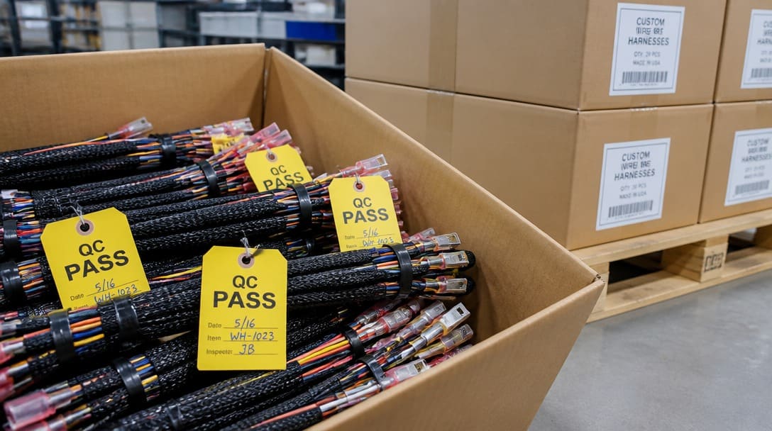
For export-bound OEM programs, the same sign-off record should flow into final QC and shipment preparation, so the approved splice types are traceable through quality inspection and export packaging. If a changed splice part number appears at the packing stage without an updated approval record, the shipment is not ready to leave.
Frequently Asked Questions
When should I approve a butt splice instead of a parallel splice?
Approve a butt splice connector when the splice is part of an inline tensile run and must carry linear pull through the harness. A butt splice with a tin-plated copper barrel maintains conductor axis and resists separation in straight sections.
When is a parallel splice the correct choice?
Approve a parallel splice connector only for branch taps, pigtails, or non-pull connections where two conductors are folded into a side-by-side configuration. It is not designed as an inline tensile path and should not be used where vibration or pull load acts along the splice axis.
Does UL 486C apply to all splices on a wire harness BOM?
UL 486C provides recognized component performance requirements for conductor termination when applicable. Not every splice line requires a UL listing, but when the harness specification or end product standard calls for recognized terminations, request listing evidence before approval. Do not assume a generic insulated crimp terminal meets UL 486C unless the supplier documents it.
What acceptance criteria should I request for splice samples?
Request IPC/WHMA-A-620 workmanship evidence covering conductor crimp integrity, insulation support, bellmouth and conductor brush, and pull force by wire gauge AWG, as covered in Top 10 Electrical Specifications for Cable Assembly & Wiring Harness. For environmental sealing, also request heat shrink tubing placement verification. Documentation should reference the standard and include pass/fail results per splice type.
What are the most common BOM errors with mixed splice part numbers?
The most common errors are a parallel splice assigned to a tensile run, a butt splice placed in a flexing conduit without strain relief, mixed AWG sizes in one barrel, missing UL listing evidence, and no insulation support verification. Each of these is a desk-rejectable issue before sample production.
Key Takeaways
- Separate every BOM splice line into an inline tensile path or a branch tap before comparing crimp styles; orientation decides the baseline approval.
- Use the go/no-go table to filter butt vs parallel splices against load path, bundle diameter, strain relief, insulation, and service environment.
- Reject splice lines upfront when AWG falls outside the barrel range, insulation ratings miss the operating environment, UL 486C evidence is absent, or barrel finish is unspecified.
- Anchor all approved splice samples to IPC/WHMA-A-620 evidence for crimp integrity, insulation support, and pull force, including heat shrink tubing where environmental sealing is required.
- Lock the approved splice orientation by line item and define rejection triggers so production substitutions cannot introduce the wrong splice into a tensile run.
For OEM and wholesale buyers coordinating mixed splice BOMs, working with a supplier that provides electronic connector sourcing and specification review can reduce approval risk before samples are built.