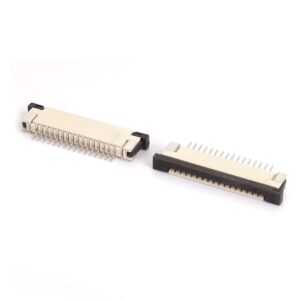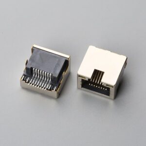
Direct answer: Board-to-board connector pitch is the center-to-center distance between adjacent contacts, and selecting 0.80 mm, 2.00 mm, or 4.00 mm pitch directly changes current per contact, mated stack height, allowable board-to-board misalignment, and field repairability in PCB mezzanine assemblies, so pitch cannot be approved from a BOM line alone.
At a Glance
Pitch is not a density upgrade by itself. A 0.80 mm pitch is often the smallest practical choice for mixed-signal mezzanine stacks, while 2.00 mm and 4.00 mm pitches suit higher-current, field-serviceable designs. Return any BOM line that lacks current rating and mated height to the supplier before quotation or sample approval.
A supplier BOM lists 0.5 mm, 0.8 mm, and 1.27 mm mezzanine connectors with only pitch and part numbers. Or an engineering team is told a 0.4 mm pitch board-to-board connector will save space without anyone checking PCB stack-up tolerance. The hidden trap is that fine pitch is usually mistaken for a simple density upgrade. What actually changes is the connector’s allowable misalignment, current per contact, and sensitivity to board warpage and standoff height. A sourcing partner such as EDOM Electronics can support this review with drawing requests, connector matching, sample coordination, production follow-up, inspection, and export-ready packaging for the associated interconnect assembly.
How to Compare Board-to-Board Connector Pitch for Mezzanine PCB Stack-Ups
Step 1: Screen Pitch in a Go/No-Go Table Before Any Quotation
Start with a screening table, not a catalog choice. For every pitch, run current per pin, minimum board-to-board stack height, misalignment tolerance, mating cycles, and field repairability. If any column is unreachable for the actual PCB stack-up, mark that pitch as no-go. A 2.00 mm or 4.00 mm pitch part does not belong in the same mezzanine density class as a 0.80 mm part; evaluate those only when current handling and field service override board real estate constraints.
| Pitch | Current per contact | Minimum board-to-board stack height | Misalignment tolerance | Mating cycles / durability | Field repairability |
|---|---|---|---|---|---|
| 0.40 mm | Supplier-dependent; lowest current class | Must be confirmed from mated height drawing; fine-pitch low-profile | Very tight; board warp and solder mask registration critical | Series-dependent; lower than coarse pitch | Poor; specialized rework tools required |
| 0.50 mm | Supplier-dependent; lowest current class | Must be confirmed from mated height drawing | Tight; standoff height mismatch can open contacts | Series-dependent; lower than coarse pitch | Poor; manual touch-up difficult |
| 0.635 mm | Supplier-dependent; mid-range between 0.50 mm and 0.80 mm | Moderate; verify mated height | More forgiving than 0.40 mm and 0.50 mm | Moderate | Moderate |
| 0.80 mm | Supplier-dependent; often the smallest pitch considered for mixed-signal power | Moderate; verify mated height | Moderate | Moderate | Moderate |
| 1.00 mm | Supplier-dependent; mid-range | Moderate | More forgiving | Moderate | Good manual inspection |
| 1.27 mm | Supplier-dependent; above fine-pitch current class | More forgiving | Absorbs typical board thickness and warp variation | Higher | Good; manual soldering feasible |
| 2.00 mm | 2.0 A max per contact documented for a dual row SMD female pin header | Profile depends on top/bottom entry; see supplier drawing | More tolerant | Moderate/high | Good |
| 2.54 mm | 3 A per contact documented for a machined socket; 500 cycles min | 4.20 mm profile documented for one machined socket | High tolerance | 500 cycles min documented | Excellent manual inspection and rework |
| 4.00 mm | 3.0–5.0 A max per contact documented for a through-hole tuning fork header | Through-hole; higher profile | Very tolerant | Higher | Excellent |
Documented values above are catalog examples. Actual performance depends on contact material, plating, ambient temperature, duty cycle, PCB pad design, and supplier qualification data.
Step 2: Check Mated Height and Standoff Tolerance — Not Just Pitch
Mated height, also called stack height, is often the real constraint. Two PCBs may pass continuity independently but open after stacking if the standoff height or solder mask registration is slightly off. For 0.40 mm and 0.50 mm mezzanine systems, standoff height tolerance can be sharply limited. A 1.27 mm or 2.54 mm pitch part absorbs more board warp and PCB thickness variation because the larger contact geometry is less sensitive to small coplanarity errors.
A BOM line that omits mated height omits the dimension that determines whether a fine-pitch part survives assembly and field vibration. Request supplier drawings for mated height, tail coplanarity, and recommended PCB pad layout before costing or approving the BOM. Pitch alone tells almost nothing until it is paired with these dimensions.
Step 3: Compare Current per Contact Across Pitches
Current per contact falls as pitch shrinks, but actual values must come from supplier rating data. A 0.40 mm pitch connector is generally limited to the lowest current class, while 1.27 mm and 2.54 mm pitch connectors carry substantially more current per pin. For example, a documented 2.00 mm dual row SMD female pin header, such as the 2.00mm Pitch Dual Row Female Pin Header (SMD, Top Entry) is rated at 2.0 A max per contact, a 4.00 mm through-hole tuning fork header at 3.0–5.0 A max per contact, and a 2.54 mm machined socket at 3 A per contact.
Fine-pitch current crowding occurs when one contact carries more than its share because of uneven mating or a weak solder joint. That concentrated current causes localized Joule heating, which induces thermal stress relaxation in the contact spring, reduces contact normal force, and accelerates oxidation. If the BOM has no current rating, do not assume all pins share load equally. Derate by pin count, ambient temperature, and duty cycle. The 0.635 mm pitch sits between 0.50 mm and 0.80 mm for density and current capability, and is often overlooked in quick comparisons but useful in industrial data modules. In many mixed-signal stack-ups, 0.80 mm becomes the smallest safe pitch for power-carrying pins.
Step 4: Apply IPC/WHMA-A-620[1] and IPC-A-610[2] Acceptance Criteria to Missing BOM Data
IPC-A-610 defines acceptance criteria for soldered electronic assemblies, including connector mounting and solder fillet requirements such as heel fillet, toe fillet, side fillet, coplanarity, and lead damage limits. IPC/WHMA-A-620 defines workmanship acceptance classes for cable and wire harness assemblies and becomes relevant when the board-to-board connector is part of a larger electromechanical assembly. Missing tail coplanarity data prevents verification of Class 2 or Class 3 solder joint criteria because fine-pitch leads may appear acceptable but contain latent open joints. Mated height is a mechanical stack-up requirement; missing mated height can hide post-assembly open contacts but does not by itself prevent IPC-A-610 solder joint verification.
For 0.40 mm and 0.50 mm connectors, solder mask registration and pad design directly influence wetting. A pitch-to-solder mask mismatch can create bridging or insufficient fillet. Ask the factory or supplier for the intended IPC class, coplanarity specification, and mated height drawing before incoming inspection or sample sign-off. For export, also confirm whether RoHS-compliant options are required for the connector body and terminal finish.
Step 5: Review What Goes Wrong in the Field After Fine-Pitch Stack-Ups
Total cost of ownership is governed by field behavior, not connector unit price. The common failure modes are:
- Cracked solder joints from fine-pitch board warpage: 0.40 mm and 0.50 mm connectors have small solder pads and stiff leads, so PCB flexure transfers stress directly into the joints.
- Open contacts from standoff height mismatch: prototypes pass single-board continuity but open after two PCBs are stacked because the mated height is slightly off.
- Current crowding: when one fine-pitch contact carries more than its share, localized heating induces contact stress relaxation, degrading normal force and accelerating oxidation.
- Contamination trapped in sub-0.80 mm gaps: flux residues, dust, or moisture are harder to clean under low standoff heights, increasing electrochemical migration risk.
- Poor field repair access: 0.40 mm and 0.50 mm connectors are difficult to inspect and rework manually, while 1.27 mm and 2.54 mm allow manual soldering and touch-up without specialized tooling.
Step 6: Create an Inspection-Ready BOM Line Before Sample Approval
For each pitch, create a go/no-go row using current per pin, stack-up tolerance, mating cycles, and field repair access. Send missing data requests back to the supplier before quotation. During sample coordination, verify mated height with gauge blocks or cross-section, and review solder paste stencil and pad design for the selected pitch. Inspection should include continuity after stacking, not only on single boards; test open/short behavior under slight flexure and, where possible, at elevated temperature.
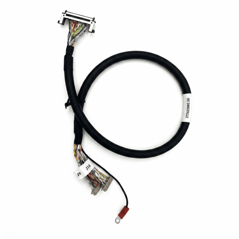
Production and export documentation should record the accepted pitch, mated height, contact plating, and IPC class so distributors and OEM teams receive repeatable product. For box-build programs where board-to-board connectors interface with routed cable assemblies, coordinate drawing review with wire harness manufacturing support early so that pitch decisions do not conflict with harness routing or strain relief. Record the accepted parameters in production and export records; see quality inspection and export packaging guidance for repeatable shipment preparation.
When a fixed PCB stack height or long-lead-time mezzanine connector blocks prototype build schedules, EDOM Electronics supports engineering and sourcing teams with cross-brand pin-to-pin connector matching, mated-height drawing verification, and 3–5 day rapid prototyping for board-to-board interconnects and custom jumper harnesses. Use drawing and coplanarity confirmation as the hard gate: if a vendor cannot document current derating and tail coplanarity, flag the BOM line before committing to tooling or SMT stencil fabrication.
Step 7: Re-Run the Go/No-Go Table and Lock the Final BOM
Re-run the decision table with actual stack height tolerance, pin current, mating cycle requirement, and field repairability for the target application. If 0.40 mm or 0.50 mm can only pass by assuming zero board warpage, reject or derate that line before committing to a prototype build. If current per pin exceeds fine-pitch capability, step to 0.80 mm or 1.27 mm and recalculate pin count, connector width, and board real estate impact. The 0.635 mm and 1.00 mm pitches are mid-range options that balance density, current, and tolerance when neither 0.50 mm nor 1.27 mm fits cleanly. Final BOM documentation should state pitch, mated height, current rating, coplanarity, and mating cycle requirement next to each connector line.
Frequently Asked Questions
Is 0.40 mm pitch safe for board-to-board mezzanine connectors?
Only if mated height, tail coplanarity, current per pin, PCB stack-up tolerance, and solder mask registration are all confirmed. A 0.40 mm pitch connector can work in a tightly controlled design, but it is not a drop-in density upgrade and should not be approved from pitch alone.
What matters more: pitch or mated height?
Usually mated height is the more direct constraint. A 0.50 mm pitch prototype can pass single-board continuity and then open after the two PCBs are stacked because the standoff height is slightly off. A larger pitch such as 1.27 mm or 2.54 mm absorbs more of that variation.
Can 2.00 mm or 4.00 mm pitch replace 0.80 mm pitch without board redesign?
No. A larger pitch changes footprint, current capacity, connector width, profile, and board real estate. Board placement, pad layout, solder stencil, and mechanical stack height must be re-evaluated before a 2.00 mm or 4.00 mm pitch connector is introduced into a design originally intended for 0.80 mm.
How do IPC-A-610 and IPC/WHMA-A-620 help when BOM data is missing?
IPC-A-610 defines acceptance criteria for connector mounting and solder fillet formation. IPC/WHMA-A-620 defines workmanship classes for cable and wire harness assemblies in electromechanical systems. Without coplanarity data, Class 2 or Class 3 solder joint verification cannot be completed because fine-pitch joints may appear acceptable but contain latent opens. Missing mated height affects mechanical matching and can hide post-assembly open contacts; verify mated height against the supplier drawing and mechanical stack-up requirements.
When should a buyer reject a BOM line instead of quoting it?
Reject or defer a BOM line when the supplier cannot provide current rating, mated height drawing, contact plating, tail coplanarity, and basic material information for a fine-pitch connector. An incomplete line cannot be costed or inspection-approved without creating field reliability risk.
Key Takeaways
- Never approve 0.40 mm, 0.50 mm, or 0.80 mm pitch based on board density alone; current per pin, stack height, misalignment tolerance, mating cycles, and repairability must pass first.
- 0.80 mm is often the smallest safe pitch for mixed-signal mezzanine stacks; 2.00 mm and 4.00 mm suit higher-current, field-serviceable designs when board space allows.
- Request mated height, tail coplanarity, and current rating from the supplier before quotation or sample approval.
- Test continuity after stacking under slight flexure, not only on single boards; verify stack height with gauge blocks or cross-section.
- Record pitch, mated height, current rating, contact plating, and IPC class in the final BOM and export documentation for repeatable supply.
For programs that combine board-to-board connectors with cable assemblies or wire harnesses, explore custom cable assembly solutions to coordinate drawing review, connector matching, and inspection before shipment.