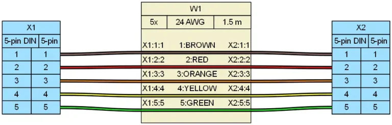
Direct answer: A cable continuity test (see What Is a Cable Tester? Function and Quality Inspection Uses) is a low-resistance electrical verification (typically requiring < 1 Ω to 2 Ω after lead resistance nulling) that confirms an unbroken conductor path between termination points in a wire harness or cable assembly. Executed via an automated harness analyzer for 100% production screening or a calibrated DMM/ohmmeter for first-article and bench QC, it detects open circuits, unintended shorts, and pinout errors against an approved engineering drawing.
At a Glance
Continuity is only a valid pass/fail decision when it runs as a fixed sequence: lock the connector into a fixture, verify the drawing revision and pinout, test every circuit against a recorded low-resistance threshold, screen adjacent pins for unintended short circuits, and flex the cable at the backshell before re-testing. A continuity beep alone cannot prove a reliable electrical path or mechanical terminal retention.
Does Your Continuity Result Actually Deserve Pass/Fail Authority?
One incoming batch passed the supplier’s continuity printout but threw intermittent opens on pin 7 the moment the cable was flexed. Another golden sample beeped clean while production cables failed only when seated in a test fixture. If either situation sounds familiar, the issue is not the multimeter; it is the decision authority granted to a single continuity beep.
A DMM in continuity mode produces an audible indication when the measured resistance falls below the meter’s internal threshold. That beep can be produced by a single strand of a nearly broken conductor, or by probe pressure temporarily closing an open circuit inside a socket. The test passes on the bench and fails in routing, vibration, or final mating. The real question is whether the continuity result can survive connector seating, mechanical flex, and repeated probing — not whether it makes a noise once.
The practical fix is a QC continuity go/no-go checklist: a fixed sequence executed against a known pinout, under fixture conditions, with the cable flexed at the backshell after each circuit or after the full sequence. The goal is to turn continuity from a convenience check into a defensible pass/fail decision.
Which Baseline Must Be Locked Before You Touch the Meter?
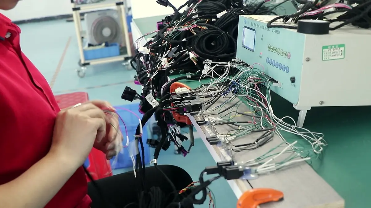
Continuity testing produces meaningful data only after the test baseline is locked. The first action is confirming the current drawing revision and approved pinout against the physical wire harness. Pinout drift after an engineering change can make a correct continuity measurement look like a miswire detection — or worse, can leave an open circuit undetected because the operator tested against an obsolete net list.
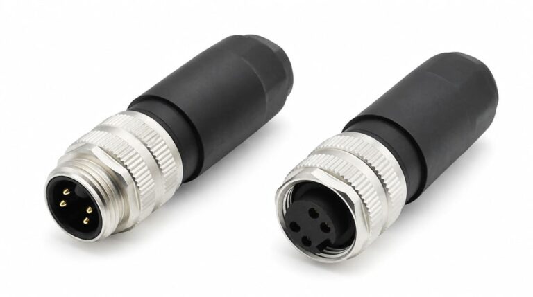
Identify the connector family, keying, and seating condition before using a DMM in continuity mode or an ohmmeter. The test must replicate final mating, not bench-only contact. A connector that seats loosely in a hand-held probe arrangement may read continuous while failing in the actual mating connector. Record the meter setup and the low-resistance threshold used for continuity mode so the pass/fail call does not drift between operators or shifts. Any unresolved drawing or pinout mismatch is a hold condition — not a variable to resolve by probing.
In production environments where multiple wire harness variants flow through the same inspection station, a missing drawing revision check is a common root cause of batch misdisposition. When custom cable assemblies are involved, engineers should treat the approved sample, the BOM, and the pinout table as inseparable references.
How Do You Build a Repeatable Continuity Test Setup Without Chasing Intermittents?
A repeatable continuity test setup begins with mechanical control and contact protection. Lock the connector into a dedicated mating test jig or breakout fixture instead of pushing bare DMM probe tips directly into female sockets. Direct probing risks splaying spring contacts—causing permanent mating failure—while probe pressure can temporarily force an open crimp closed and mask the defect. The fixture must replicate the exact mating pin geometry, orientation, and insertion depth of the final application.
Before testing pin-to-pin, zero out (null/REL) the test lead and fixture resistance—or use a 4-wire Kelvin setup—so lead resistance (typically 0.2 Ω to 0.5 Ω) does not skew low-ohm readings. Because standard DMM continuity beepers trigger anywhere below 10 Ω to 50 Ω, a simple beep can easily pass a high-resistance cold solder joint or a 90%-severed wire. Require a stable, numeric low-resistance reading (e.g., < 1 Ω for short harnesses, adjusted for AWG conductor resistance per meter) rather than relying on an audible tone alone.
After each circuit — or at minimum after the full sequence — add a flex-at-backshell step. Bend, rotate, or lightly load the cable at the connector backshell while the circuit remains under test. This action exposes single-strand contact, loose crimps, and intermittent opens that pass a static DMM check. Re-test any circuit that changed state during flex. If a circuit reads clean only after reseating the connector or repositioning the test lead, classify it as suspect rather than cleared.
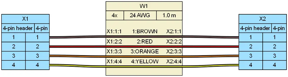
The QC Continuity Go/No-Go Decision Tool: Expected Results and Reject Triggers
The decision tool below consolidates the test sequence into a single screenshot-ready table. Each row pairs a test step with an expected result and a rework or reject trigger. Acceptance thresholds should align with IPC/WHMA-A-620[1], which defines three workmanship classes for cable and wire harness assemblies with increasing inspection and documentation rigor.
| Test Step | Method / Condition | Expected Pass Result (Typical Baseline) | Rework / Reject Trigger (IPC/WHMA-A-620) |
|---|---|---|---|
| 1. Lock connector into mating fixture | Mate with dedicated test header (no bare probes in female sockets); apply light axial tug | Full latch engagement; zero terminal back-out (push-back); polarization keys aligned | Terminal push-back, bent pins, splayed female contacts, or housing deformation |
| 2. Verify drawing revision, BOM & netlist | Cross-check physical wire markers and cavity numbers against latest released print | 100% netlist match to active revision; test leads/fixture nulled (0.0 Ω baseline) | Drawing revision mismatch, swapped cavities (cross-wiring), or unzeroed lead offset |
| 3. Measure pin-to-pin circuit continuity | 4-wire harness analyzer or nulled DMM ohmmeter across all mapped nets | Stable resistance below spec limit (typically < 1.0 Ω to 2.0 Ω for standard harnesses) | Open circuit (OL), resistance exceeding AWG/length budget, or fluctuating reading |
| 4. Screen for unintended short circuits | Pin-to-adjacent-pin, net-to-net, and pin-to-braid/shield isolation scan | Open / Over-Limit (OL) on all non-commoned nets and shield drain paths | Any low-resistance bridge, solder whisker short, or stray strand across cavities |
| 5. Dynamic flex test at backshell / strain relief | Flex cable ±45° to 90° behind connector backshell while monitoring live resistance | Continuous reading with minimal resistance drift (typically ΔR < 0.2 Ω) | Momentary open ( > 1 μs on analyzer), intermittent beep, or resistance spike |
| 6. Insulation resistance (IR) / DWV (Hi-Pot) | Apply specified DC/AC test voltage (e.g., 100–500 VDC for IR) when required by Class 2/3 | IR typically > 10 MΩ to 100 MΩ; zero dielectric breakdown or flashover | Leakage current trip, insulation breakdown, or IR below customer drawing spec |
Anchoring the go/no-go tool to IPC/WHMA-A-620 acceptance criteria makes batch disposition defensible. The standard distinguishes applicable workmanship classes, so the same continuity checklist can be applied with stricter mechanical and documentation requirements when a customer specifies a higher product class.
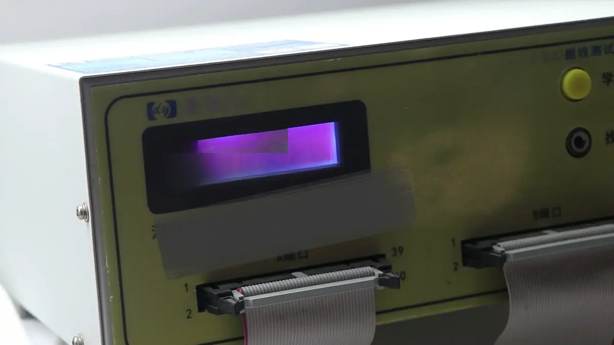
What Goes Wrong in the Field: Why Intermittent Opens Escape a Continuity Beep
Intermittent opens escape a continuity beep for four common reasons, and each traces back to treating continuity as a one-time event rather than a sequence.
Probe pressure masks open circuits. A test lead pressed firmly into a socket can create temporary contact that disappears after shipment and repeated mating cycles. The operator sees a pass, reseats the lead for the next pin, and never realizes the pass was produced by the probe itself.
Single-strand contact produces a false pass. A beep confirms that at least one conductive strand remains linked between two points. It does not confirm sufficient cross-sectional contact for the operating current or mechanical load. The cable passes on the bench and opens once the wire harness is routed, bundled, or flexed inside the equipment.
Pinout drift after an engineering change. When a supplier works to an obsolete net list, continuity still beeps on every circuit because the wrong wire is continuous to the wrong pin. The harness is miswired against the current drawing while the continuity printout remains clean.
Connector seating issues clear on reseat. A backed-out terminal or damaged retention feature may open when the connector is first seated and then clear when the operator reseats it. The reseat itself masks the physical defect, and the circuit is declared good without a flex re-test.
Why Continuity Cannot Validate Crimp Retention — and What Must Follow
Continuity confirms the electrical path but not the mechanical retention of a terminal. A loose crimp can read continuous while failing under vibration, wire movement, or repeated mating cycles. When a wire harness passes continuity but fails crimp height or pull force, IPC/WHMA-A-620 acceptance criteria still require corrective action. Electrical continuity does not override mechanical retention evidence.
The same go/no-go decision must include crimp height measurement and pull force testing where the customer drawing or the applicable workmanship class requires them. Add flex-at-backshell checks to the continuity sequence because a terminal that is electrically continuous but mechanically marginal often changes resistance when the cable is flexed at the connector backshell. Use insulation resistance or hi-pot screening only where specified, to catch insulation damage continuity cannot detect — keeping the inspection proportionate to the product class and application.
For procurement teams managing OEM wire harness programs, this is where coordinated manufacturing support becomes valuable. Suppliers working across wire harness production with accessible fixture tooling, crimp height records as detailed in How Manufacturers Ensure Consistent Cable Assembly Quality?, and batch-level documentation provide a stronger basis for pass/fail disposition than a single continuity printout generated without controlled conditions.
How Do You Issue a Pass/Fail Disposition on a Suspect Harness Batch?
If any circuit fails the go/no-go tool under fixture or flex conditions, do not clear the batch by reseating the connector or wiggling the lead. Record the failure and move to rework or rejection based on the defect class. For intermittent opens that appear only on repeated flex cycles, segment the inspection lot and trace the failure to a specific cavity, wire, or crimp location before releasing the batch for export packaging.
A harness that passes continuity but fails crimp height or pull force must still be rejected or rewired per IPC/WHMA-A-620. Mechanical retention evidence cannot be overridden by an electrical pass. Document the full pass/fail evidence package: drawing revision, meter threshold, fixture ID, flex step result, operator, and date. This audit trail determines whether an export hold can be lifted or must be sustained.
Buyers managing inbound custom cable assembly programs should require that suppliers retain this documentation for each inspection lot. The same evidence set that supports a batch release also supports returns analysis when field failures surface after shipment.
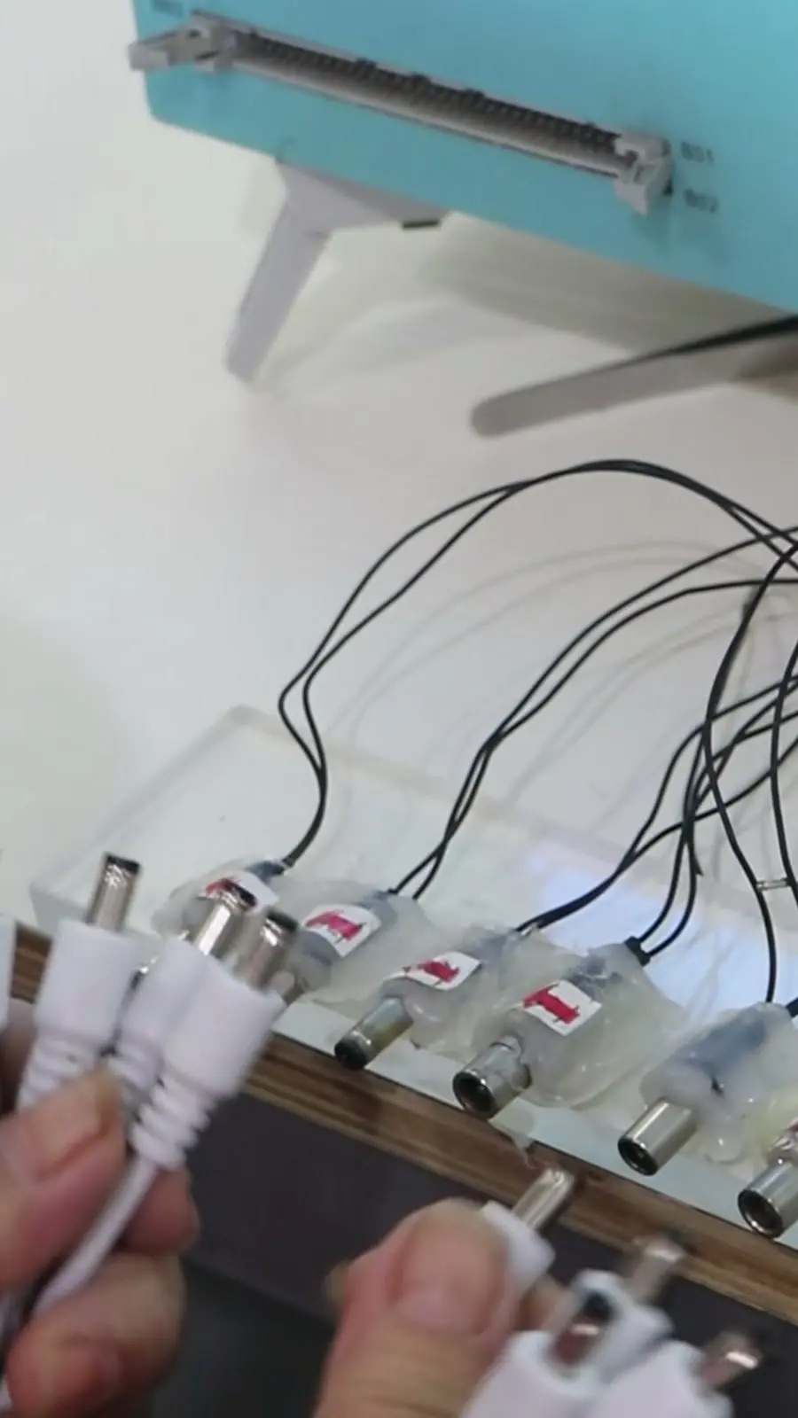
Final Rule: Treat Continuity as a Sequence, Not a Sound
A single beep is not a pass. Only a repeated pin-to-pin reading under fixture conditions, flex at the backshell, short-circuit screening, and mechanical checks can justify a pass/fail decision on a wire harness or cable assembly. Build the go/no-go tool into incoming inspection and pre-shipment verification so export packaging is never opened under unresolved intermittency. If the result changes when the connector is reseated or the probe is repositioned, treat the change itself as the finding — not the re-test as the verdict.
Eliminating intermittent field failures starts before production: it requires custom mating test fixtures built alongside your harness tooling, automated 100% pinout/short analyzers, and IPC/WHMA-A-620 crimp height and pull-force logs tied to every shipment. At EDOM Electronics, we build dedicated continuity and flex-test jigs into our custom cable assembly supply workflow—delivering fully tested rapid prototypes in 3–5 days and batch-traceable QC reports prior to export packaging.
Frequently Asked Questions
Why does a cable pass continuity but fail in the field?
A cable passes continuity but fails in the field when the beep is produced by a single strand of a nearly broken conductor, by probe pressure temporarily closing an open circuit, or by a loose crimp that remains electrically continuous until the wire is flexed at the connector backshell. Continuity confirms an electrical path exists at the moment of testing; it does not confirm mechanical retention or stability under load.
What is the difference between continuity mode and an ohmmeter reading?
Continuity mode on a DMM gives a go/no-go indication when resistance falls below the meter’s internal threshold (often 10 Ω to 50 Ω). An ohmmeter or 4-wire micro-ohmmeter provides a numeric resistance value after lead nulling. The numeric reading reveals marginal connections and resistance drift during flex, which a continuity beep can mask.
How do you test for a short circuit in a wire harness?
Screen each pin against adjacent pins, nets, and shield in the same fixed sequence as the continuity check. A short circuit appears as continuity or a low-resistance path between points that should not be connected. This step must run after pin-to-pin continuity testing and before any insulation resistance or dielectric check.
Does continuity testing validate crimp quality?
No. Continuity confirms the electrical path but not the mechanical retention of a terminal. Crimp quality requires crimp height measurement and pull force testing against IPC/WHMA-A-620 acceptance criteria or customer drawing requirements. A loose crimp can read continuous while failing under vibration or wire movement.
What should a continuity test procedure include for incoming inspection?
A continuity test procedure for incoming inspection should include drawing revision verification, mating fixture locking, test lead zeroing, pin-to-pin continuity at a recorded low-resistance threshold, short-circuit screening, flex-at-backshell re-testing, and insulation resistance or hi-pot checks where the product specification requires them. The procedure should define hold and reject triggers before testing begins.
Key Takeaways
- Continuity is only a valid pass/fail decision when executed as a fixed sequence against a known pinout, not as a single DMM beep.
- Lock the connector into a fixture, record the low-resistance threshold, and add a flex-at-backshell re-test to catch intermittent opens.
- Anchor acceptance thresholds to IPC/WHMA-A-620 workmanship criteria and document drawing revision, fixture ID, operator, and flex results for every batch disposition.
- Continuity cannot validate crimp retention; pair it with crimp height, pull force, and insulation resistance checks where specified.
- Never clear a suspect harness batch by reseating the connector — treat any result that changes on reseat or probe reposition as a finding, not a pass.
Learn more about quality inspection and export packaging support for OEM cable assembly and wire harness programs.
Need 100% Fixture-Tested Harnesses with Full IPC-A-620 QC Reports?
Send us your drawing or BOM for a free DFM & testability review, custom test-fixture matching, and 3–5 day rapid prototyping.