2022年1月3日
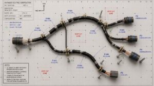
10 tips when sending cable assembly samples
Cable assemblies are an essential part of any electronic device. If you’re a supplier, chances are that at...

Rapid Prototyping in 3-5 Days
B2B Electronic Connection Solution
Factory-backed connector sourcing and electric connection support for OEMs, distributors and electronic equipment manufacturers.
OEM Ready
Factory Supply
Fast Quote
Product Specifications
Key parameters for OEM, distributor and engineering evaluation.
Detailed Product Information
Structured parameters, material notes, application context and frequently asked questions for engineering and procurement evaluation.
Intermateable: This part is mechanically and electrically compatible for mating with the listed competitor connector. Mixed use in the same connector system is supported.
| Material | Value / Description |
|---|---|
| Insulator Material | Black PPS (Polyphenylene Sulfide), UL94V-0 |
| Outer Sleeve (Pin) Material | Machined Brass (CuZn38Pb2) |
| Inner Contact (6-Finger Clip) Material | Heat-Treated Beryllium Copper (BeCu) |
| Characteristic | Value |
|---|---|
| Current Rating | 3 Amps |
| Contact Resistance | 10 mΩ Max. |
| Dielectric Withstanding Voltage | 1000V RMS Min. |
| Insertion Force | 1.2N Typical (Measured with Ø0.66mm Polished Steel Gauge) |
| Withdrawal Force | 0.6N Typical (Measured with Ø0.66mm Polished Steel Gauge) |
| Operating Temperature Range | -40°C to +105°C |
| Soldering Temperature | +255°C Max. |
| General Tolerances | X. ±0.30mm; .X ±0.25mm; .XX ±0.15mm; .XXX ±0.10mm |
Industrial Programmable Logic Controllers (PLCs) and I/O Expansion Modules
High-Vibration Board-to-Board Stacking in Embedded Computing and Single Board Computers (SBCs)
Precision Test, Measurement, and Automated Inspection Equipment (ATE)
Pluggable Sensor Modules, Daughterboards, and Field-Replaceable IC Packages
Medical Diagnostic Instrumentation and Power Control Boards
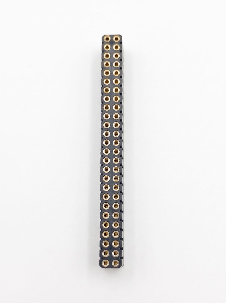
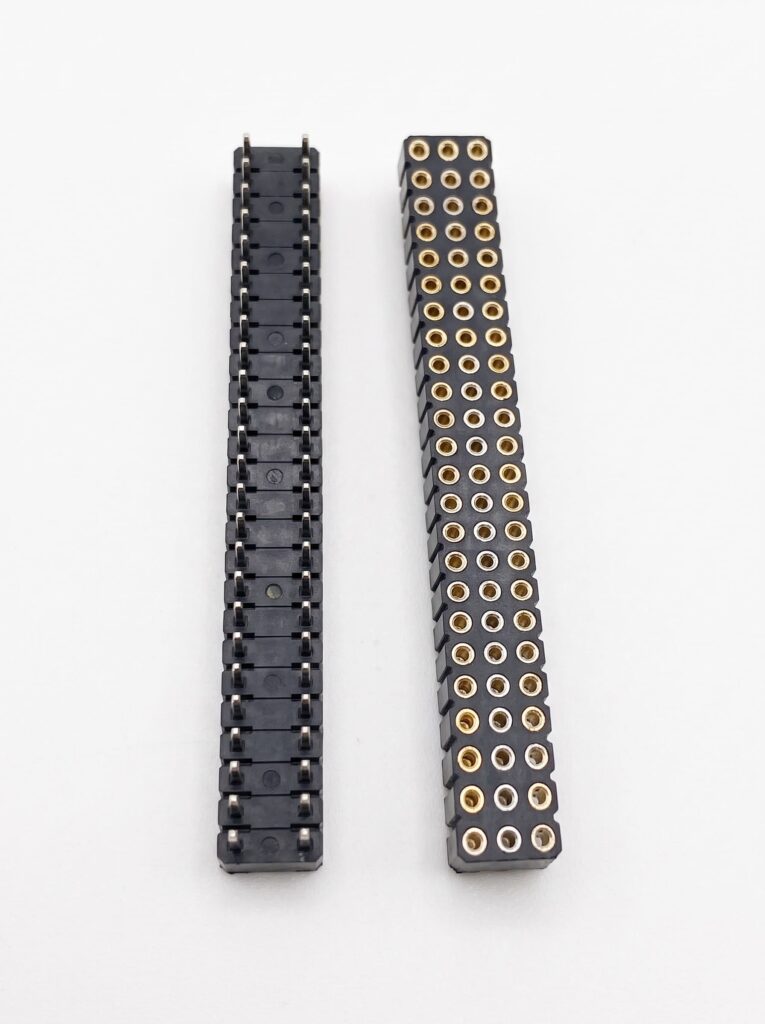
The 2.54mm pitch machined female socket strip connector is engineered for high-reliability board-to-board and IC package interconnects. Featuring a straight through-hole (DIP) mounting configuration with a 4.20mm insulator profile height and 7.40mm overall mating height, this precision-turned socket incorporates a 6-finger heat-treated beryllium copper contact clip inside a machined brass sleeve. It ensures gas-tight electrical continuity and high shock/vibration resistance across industrial automation, embedded control modules, and instrumentation systems.
Designed for standard 2.54mm (0.100 inch) grid through-hole PCB layouts, the terminal tail diameter measures Ø0.60mm ±0.02mm, requiring a recommended finished PCB plated through-hole (PTH) diameter of Ø1.00mm ±0.05mm. The total connector length scales linearly according to the formula 2.54mm × Number of Positions (±0.40mm), with a pin-to-pin pitch tolerance of 2.54mm ±0.10mm. Ensure wave or selective soldering profiles do not exceed +255°C peak temperature to maintain insulator dimensional stability.
2022年1月3日
Cable assemblies are an essential part of any electronic device. If you’re a supplier, chances are that at...
2024年3月11日
Introduction Begin with an introduction to the importance of custom wire harness design in various industries. Emphasize how...
2026年8月1日
Learn aerospace cable harness design to AS50881, material compatibility, and sourcing checks for airworthiness. Get a certifiable harness—read...
2026年6月28日
Find certified aerospace wire harness manufacturers. Our guide covers IPC/WHMA-A-620, SAE J1128, sourcing strategies, and quality benchmarks. Get...
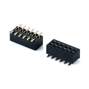
Pin socket connectors, also known as female header connectors, are electrical connectors used to mate with pin header...
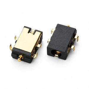
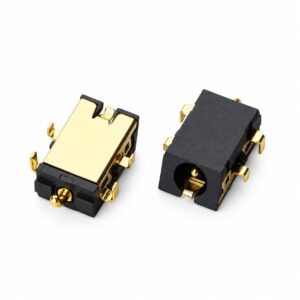
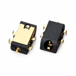
View ProductThis industrial-grade DC power jack female connector features a reverse sinking DIP (mid-mount) configuration with an ultra-low profile...
View ProductThe Reverse Sinking Mount (Mid-Mount) DC Power Jack Female Connector features an ultra-low profile height of 1.60mm combined...
View ProductThe Reverse Sinking Mount (Mid-Mount) DC Power Jack Female Connector delivers ultra-compact power delivery with a profile height...
View ProductProduct Document
Use this document for internal review, engineering comparison, and RFQ preparation.
We support importers, distributors, and electronics manufacturers with product matching, alternative sourcing, assembly integration, and factory-direct production coordination.