2026年8月1日
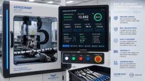
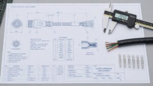
Aerospace Cable Harness: Key Design and Sourcing Considerations for OEMs
Learn aerospace cable harness design to AS50881, material compatibility, and sourcing checks for airworthiness. Get a certifiable harness—read...

Rapid Prototyping in 3-5 Days
B2B Electronic Connection Solution
Factory-backed connector sourcing and electric connection support for OEMs, distributors and electronic equipment manufacturers.
OEM Ready
Factory Supply
Fast Quote
OEM & Manufacturing Advantages
Partner with us for factory-direct pricing, custom engineering, and complete compliance ready for global markets.
Custom Engineering Support
Tailored cable assembly & wire harness designs to meet your exact application requirements.
Full Technical Datasheets
Electrical ratings, mechanical drawings, material specs and compliance certifications on request.
Factory Direct Pricing
Competitive OEM & distributor pricing with flexible MOQ for both prototype and volume orders.
UL / CE Compliance Ready
Products engineered and tested to meet North American and European regulatory standards.
Need detailed parameters for this product?
Submit a quote request below -- our engineering team typically responds within one business day with full specifications, samples availability and lead times.
Detailed Product Information
Structured parameters, material notes, application context and frequently asked questions for engineering and procurement evaluation.
Functional Alternative: This part provides equivalent performance characteristics as a cost-optimized substitute. Minor design review recommended before adoption.
| Material | Value / Description |
|---|---|
| Housing Material | High-Temp Thermoplastic (PA10T), UL 94V-0, Black |
| Contact Material & Plating | Copper Alloy, Gold (Au) Plated |
| Shell Material & Plating | Copper Alloy, Gold (Au) Plated |
| Characteristic | Value |
|---|---|
| Electrical Rating | 24V DC, 3A |
| Contact Resistance | 20 mΩ Max. |
| Insulation Resistance | 100 MΩ Min. |
| Dielectric Withstanding Voltage | AC 500V (1 minute) |
| Operating Temperature Range | -55°C to +105°C |
| General Tolerances | Metric: 0 Place ±0.50mm, 1 Place ±0.35mm, 2 Place ±0.25mm, 3 Place ±0.15mm, Angular ±3° |
Single Board Computers (SBC) and ultra-thin embedded compute modules
Industrial IoT gateways and compact telemetry hardware
Portable medical instrumentation and handheld diagnostics
Commercial display panels and edge AI vision devices
Handheld test, measurement, and field service equipment
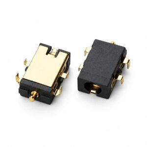
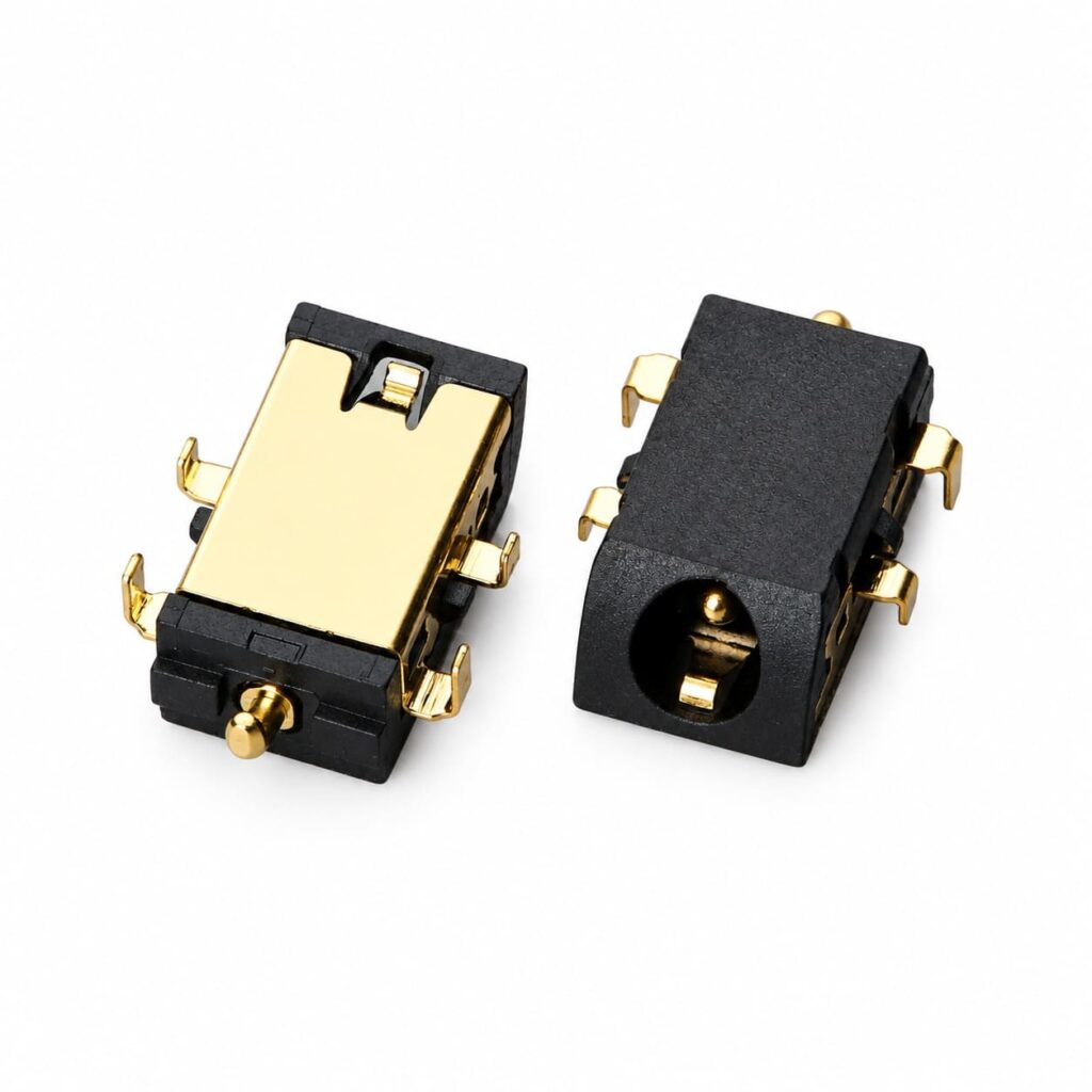
The Reverse Sinking Mount (Mid-Mount) DC Power Jack Female Connector delivers ultra-compact power delivery with a profile height of 1.60mm and a curved-mouth (arc interface) entrance design. Engineered for high-density, low-profile embedded systems, this female DC receptacle supports power ratings up to 24V 3A while maintaining robust mechanical integrity through its mid-mount reverse SMT configuration.
This female DC jack utilizes a reverse mid-mount footprint requiring a dedicated PCB edge cutout (6.90mm depth by 8.90mm width opening). The landing pattern specifies four anchor/contact pads (2.10mm x 1.50mm) spaced 10.70mm apart laterally and 8.55mm longitudinally, ensuring balanced solder joints and mechanical shear resistance during repetitive cable mating. Recommended PCB layout tolerances should be held within ±0.05mm to ensure proper alignment and coplanarity across SMT pads.
2026年8月1日
Learn aerospace cable harness design to AS50881, material compatibility, and sourcing checks for airworthiness. Get a certifiable harness—read...
2026年6月28日
Find certified aerospace wire harness manufacturers. Our guide covers IPC/WHMA-A-620, SAE J1128, sourcing strategies, and quality benchmarks. Get...
2026年8月29日
Use this cable assembly specification checklist for China sourcing to evaluate engineering depth, component traceability, and communication. Download...
2026年7月2日
What is wire processing? Cutting, stripping, crimping—these steps turn BOMs into reliable OEM harnesses. Learn how gauge affects...
This industrial-grade DC power jack female connector features a reverse sinking DIP (mid-mount) configuration with an ultra-low profile...
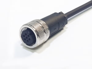
View ProductOverview Engineered for demanding industrial automation and fluid control systems, our Custom 7-Position Valve Connector to Servo Cable...
View ProductOverview: Custom Multi-Branch Industrial Wire Harness Assembly The A002-00343-001 (Customer P/N: 420343) is a complex, precision-built multi-branch wire...
View ProductThe A002-00053 custom DC power cable assembly features a DB9 9-pin male connector with backshell to a standard...
View ProductWe support importers, distributors, and electronics manufacturers with product matching, alternative sourcing, assembly integration, and factory-direct production coordination.