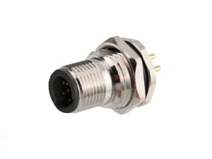
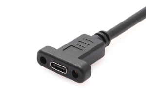
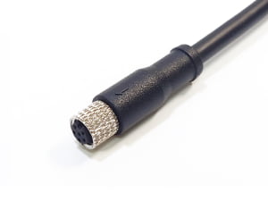
Direct answer: If you’re specifying a cable assembly and the operating environment hasn’t come up in the conversation yet, it should be the first thing on your list — not an afterthought. For medical cable assembly manufacturing, standards such as IEC 60601[1]-1, ISO 13485, and USP Class VI become decision filters only after moisture, temperature, space, and mechanical stress are defined.
What Is a Medical Cable Assembly — and How It Differs from a Wire Harness?
A medical cable assembly is not simply a bundle of wires. It is an engineered component that transmits power, signal, or data between medical devices while protecting conductors from the operating environment and repeated connection. The assembly typically includes multiple conductors, connectors at one or both ends, strain relief at termination points, and an outer protective covering. In many medical applications, that covering is overmolded to seal terminations, provide a cleanable surface, and resist flexing or pull force.
A wire harness is different. It organizes and routes a group of wires or cables mainly for installation and layout, often using loom, conduit, tape, or sleeving. A harness may reduce abrasion and simplify assembly, but it does not automatically provide the environmental sealing, fluid resistance, or cleanable surface that a sealed medical cable assembly offers.
This distinction matters because medical equipment can place the same conductors in very different risk environments. Choosing a wire harness when the application needs a sealed, cleanable, or patient-area cable assembly drives early redesign, compliance risk, and avoidable tooling changes.
| Parameter | Cable Assembly | Wire Harness |
|---|---|---|
| Definition | Multiple conductors bundled with connectors, strain relief, and an outer protective covering | Group of wires or cables routed and bundled mainly for organization and layout |
| Main function | Transmit power or signal while protecting against environment and repeated connection | Keep wiring organized within a system; simplify installation and routing |
| Outer covering | Jacket, overmold, or sealed sheath | Loom, conduit, tape, sleeving, or open routing |
| Environmental protection | Often sealed, cleanable, or moisture-resistant | May provide abrasion resistance but not always sealing |
| Typical medical use | Patient monitors, imaging handpieces, diagnostic cables, power cords with molded plugs | Internal device wiring, enclosure routing, panel wiring, non-sealed equipment interiors |
| Production complexity | Higher; includes overmolding, sealing, connector matching, and continuity testing | Moderate; focuses on cutting, stripping, crimping, routing, labeling, and looming |
For projects that are confirmed as internal wiring organization rather than sealed interconnect, review wire harness manufacturing requirements.
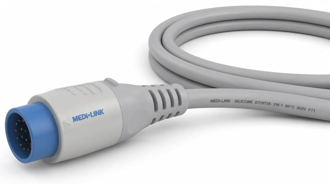
Why the Operating Environment Must Precede Material and Connector Selection
The most common early mistake is treating a medical cable assembly as a generic component and skipping environment mapping before requesting quotes. The same pin count and wire gauge can require a completely different design for an indoor diagnostic device compared with a wiped-down cart in a humid room. Environment drives insulation, jacket material, sealing method, connector type, sterilization or cleaning compatibility, and safety requirements.
Standards should be treated as decision filters, not starting points. IEC 60601-1 addresses electrical safety for medical electrical equipment. ISO 13485 addresses quality management for medical device design and manufacture. USP Class VI addresses material suitability for patient-contact applications. None of these standards replace a clear definition of where the assembly will be installed, how it will be cleaned, and how much space it must fit into.
When engineers skip the environment conversation and move directly to connector part numbers, the result is often a technically compliant assembly that still cannot be installed, cleaned, or terminated correctly inside the device. The specification process needs to begin with the operating conditions, and only then narrow down materials, connectors, and overmold geometry.
Key Medical Cable Assembly Standards You Must Know
Before discussing design mechanics, it is critical to understand the regulatory baseline. While the environment dictates the design, these standards dictate the compliance testing:
| Standard | Scope & Focus | Impact on Cable Assembly Design |
|---|---|---|
| IEC 60601-1 | Electrical safety and essential performance of medical electrical equipment. | Dictates dielectric withstand (Hipot) testing, creepage/clearance distances, and Means of Patient Protection (MOPP) to prevent shock. |
| ISO 10993 | Global standard for biological evaluation of medical devices (replacing legacy USP Class VI dependence). | Demands rigorous testing for cytotoxicity, sensitization, and skin irritation for any patient-contact jacket (e.g., medical-grade silicone). |
| ISO 13485 | Quality Management System (QMS) specifically for medical device manufacturing. | Requires full material traceability, process validation, and strict change control (no undocumented part substitutions) at the manufacturer level. |
| IPC/WHMA-A-620 (Class 3) | Acceptance criteria for high-reliability cable and wire harness assemblies. | Defines stringent requirements for soldering, crimping, and molding where equipment downtime can be life-threatening. |
The Four-Point Operating Environment Checklist Before Specification
The following four factors should be defined before any connector, jacket material, or overmold tool is chosen.
| Environment factor | Questions to answer | Design consequence |
|---|---|---|
| Moisture exposure | Is there splash, submersion, humidity, disinfectant wiping, or cleaning fluid contact? | Drives sealed overmolding, jacket choice such as silicone jacket or TPE, and connector sealing |
| Temperature range | What are the operating and storage extremes? | Affects insulation, overmold compound, connector body material, and thermal cycling sensitivity |
| Installation space | What are the panel cutouts, grommet openings, enclosure depth, and bend radius? | Constrains overmold dimensions, connector envelope, and routing path |
| Vibration or mechanical stress | Is there flexing, pull force, routing movement, or repeated mating? (e.g., patient monitor cables or ECG leads subjected to constant bed-side movement). | Informs strain relief design, jacket material, and crimp versus solder termination |
Moisture exposure
Define splash, submersion, humidity, wiping, or disinfectant exposure before selecting any material. Medical environments often demand more than basic IP68 (static submersion). Cables subjected to pressurized chemical washdowns require IP69K ratings, while reusable surgical cables must withstand autoclave steam sterilization. This aggressively limits jacket choices, often ruling out standard TPEs in favor of high-performance medical-grade silicone. A cable that only ever sits inside a dry enclosure has entirely different requirements from one wiped daily with disinfectant, such as ultrasound probe cables or endoscopic imaging lines that undergo rigorous sterilization.
Temperature range
Operating and storage extremes dictate material stability. In medical applications, the “extreme” is often the cleaning cycle. Cables undergoing autoclave sterilization must survive repeated cycles at 134°C (273°F) and high steam pressure. Conversely, cold-storage medical devices may require materials that remain flexible at -20°C. Standard commercial PVC or TPE will melt, crack, or outgas under these conditions. The connector body material must also be evaluated for the same range.
Installation space
Map panel cutouts, grommet openings, enclosure depth, and bend radius early. A connector that fits the electrical specification but not the mechanical envelope will force enclosure modification or a new cable design. Overmold dimensions are often the first casualty of an undefined installation space.
Vibration or mechanical stress
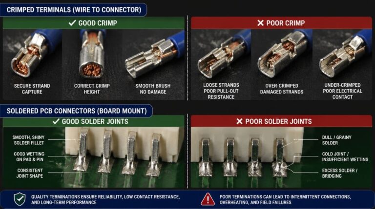
Flexing, pull force, routing, and repeated mating all influence strain relief design, jacket material, and termination type. A soldered joint may be acceptable in a static internal route, while repeated movement often favors crimped terminations and a more robust overmolded strain relief.
Coordinate a custom cable assembly drawing review with these four environmental factors defined before connector and material selection begins.
Overmolding Dimensions: Thick Enough to Encapsulate, Thin Enough to Fit
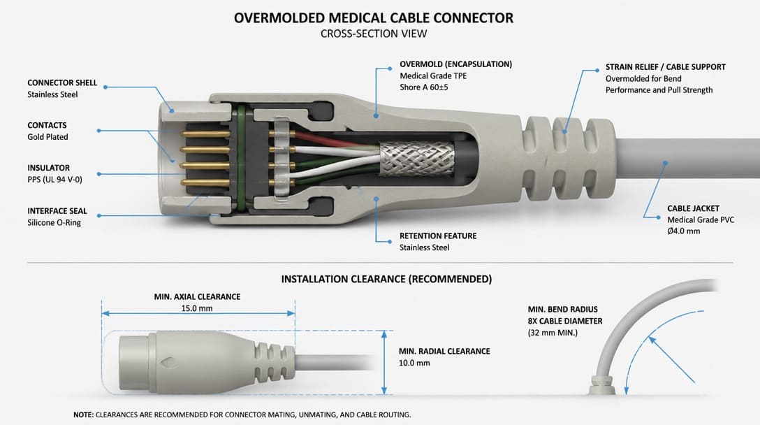
Overmolding is one of the most practical constraints in medical cable assembly design. The overmold must fully encapsulate internal solder joints, terminations, and strain relief without thin wall sections, while still fitting inside the assigned installation space. Many specification drawings ignore this dual constraint until tooling or first samples expose the problem.
Too thin covers nothing
Thin wall sections create voids, exposed internals, weak strain relief, and inconsistent geometry. A thin overmold may look acceptable on a drawing but fail during pull testing, flexing, or repeated cleaning. It also reduces the mechanical protection around terminations and makes the assembly more sensitive to handling damage.
Too thick blocks installation
An overly thick overmold prevents enclosure closure, blocks mating, or interferes with panel cutouts and adjacent connectors. In compact medical devices, the available envelope around the connector body is often extremely tight. A design can pass electrical testing and still be unusable because the overmold does not fit inside the device.
When both constraints are tight
When the assembly needs a thick enough overmold for encapsulation but the installation space is very small, internal PCB layout, grounding, and shielding arrangement must be planned as part of the cable assembly design — not after the overmold tool is committed. Adjusting board position, connector location, or shielding termination can create the mechanical clearance needed without sacrificing encapsulation quality.
Material choice affects wall thickness and performance
TPE offers flexible processing and is suitable for many general medical cable applications. Silicone jacket suits high-flex or cleaning and autoclave requirements, but may require different mechanical thickness allowances and handling characteristics. The material selection is not independent from the overmold geometry; both must be evaluated together.
Before approving overmold drawings, define mating clearance, panel cutout, grommet opening, and connector body envelope. This single step removes the most common cause of late-stage cable assembly redesign.
Shielding Decisions for Medical Cable Assemblies: Foil, Braid, or Combined
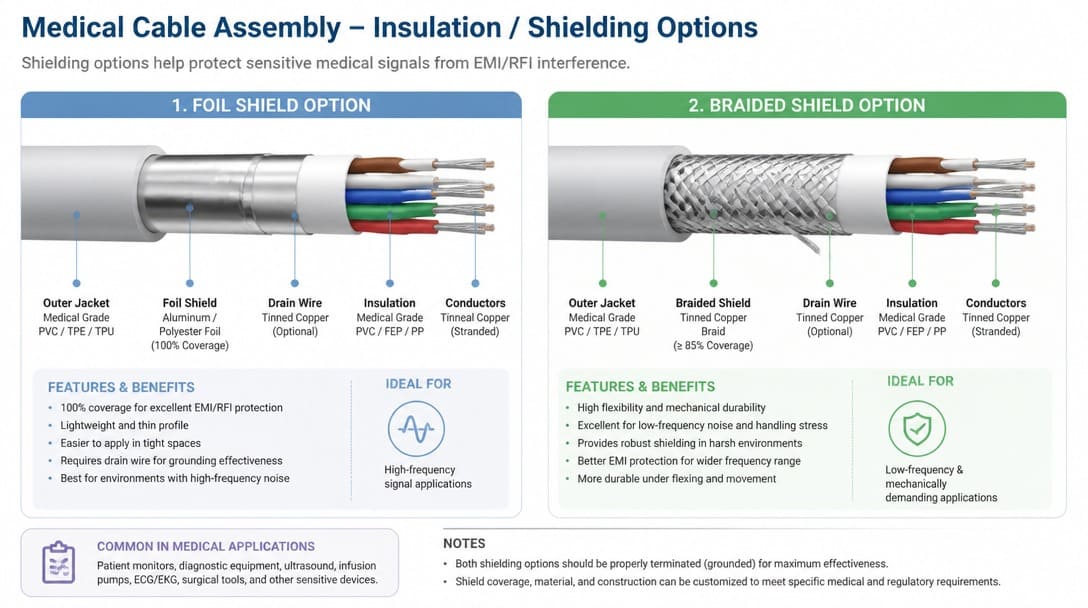
Shielding is needed when cables route near EMI sources, imaging equipment, motors, or sensitive analog signals. Not every medical cable requires full shielding. The decision should follow the operating environment and the electrical noise exposure of the specific device, not a blanket assumption that more shielding is always better.
Foil provides high coverage at high frequency and is lightweight, but it is better suited to low-flex and static routes. Braid provides stronger mechanical durability and better low-frequency performance, but adds weight, cost, and thickness. Combined foil-plus-braid offers maximum coverage and durability with a larger size and higher cost trade-off.
| Shielding type | Coverage | Flex life | Weight and cost | Typical medical use |
|---|---|---|---|---|
| Foil | High at high frequency | Lower; better for static or low-flex routes | Lightweight, lower material cost | Fixed internal wiring, imaging signal lines, static device routes |
| Braid | Good low-frequency and mechanical durability | Higher flex life | Heavier, higher cost | Patient cables, frequently flexed or pulled connections |
| Combined foil-plus-braid | Highest coverage and durability | Highest | Largest size and highest cost | Signal-critical medical equipment with both EMI exposure and movement |
Shielding performance also depends on how the drain wire and shield are terminated to the device enclosure and PCB ground. The grounding path should be specified in the drawing. Electrical safety verification under IEC 60601-1 includes insulation and leakage considerations that relate to how the shield is connected, making this an electrical safety issue as much as a signal integrity issue.
What to Include in a Cable Assembly Drawing to Avoid Redesign Cycles
A drawing that stops at connector type and wire gauge is not enough to prevent redesign cycles. The specification package should start with an environmental conditions note block, not just connector part numbers and conductor size.
We regularly see cable assembly inquiries where the drawing shows connector types and wire gauge, but nothing about where the assembly will be installed. When the answer turns out to be inside a sealed enclosure in a humid environment, the entire overmold approach needs to change.
A production-ready medical cable assembly drawing should include the following:
- Connector identification: part number, keying, locking style, pin assignment, and color code. For example, a LEMO connector or equivalent push-pull connector must be specified fully enough to avoid mating errors.
- Conductor and shielding details: wire gauge, twist or lay, shielding type and drain wire, jacket material such as silicone jacket or TPE, overmold dimensions and material, and strain relief style.
- Installation envelope: routing path, bend radius, grommet sizes, panel cutout, and connector body clearance.
- Acceptance criteria: continuity, hipot where relevant, dimensional checks, pull force, appearance inspection, and label or marking requirements.
When these details are defined before quoting, the manufacturer can identify conflicts early. Changing an overmold because the installation space was never defined is far more expensive than documenting the environment on the first drawing.
From Specification Review to Production-Ready Medical Cable Assembly
Once environment, overmold, shielding, and drawing details are defined, production coordination moves to drawing review, sample confirmation, incoming inspection, process control, continuity and appearance inspection, and final verification, as outlined in our guide to consistent cable assembly quality. For medical cable assemblies, confirming which standards apply to the specific project is part of that review. ISO 13485 addresses quality management for medical device design and manufacture. IEC 60601-1 addresses electrical safety. For patient-contact applications, ISO 10993 is the internationally recognized standard dictating strict in-vitro and in-vivo biocompatibility limits, including cytotoxicity, sensitization, and skin irritation. While USP Class VI is historically referenced, modern FDA and EU MDR submissions heavily rely on comprehensive ISO 10993 test data to approve outer jackets and overmolded connectors.These standards directly determine whether standard commercial TPEs can be used or if medical-grade silicone is mandatory for your outer jackets and overmolded connectors.
Treat the cable assembly as an engineered component with documented requirements, not a catalog commodity. Request sample approval and final verification before shipment. For workmanship and acceptance language, IPC/WHMA-A-620 defines acceptance criteria for cable and wire harness assemblies. Soldered terminations can be evaluated under IPC J-STD-001, and solderless terminations under IEC 60352. RoHS-compliant options address restricted hazardous substances in electrical and electronic equipment.
Suppliers such as EDOM Electronics support OEM buyers with requirement review, connector matching, sample coordination, production follow-up, quality inspection, and export-ready packaging for custom cable assemblies and wire harnesses. For global shipment, coordinated export packaging and pre-shipment inspection reduce the risk of connector damage, moisture exposure, or labeling errors. Learn more about quality inspection and export packaging.
Frequently Asked Questions
Do all medical cable assemblies need to meet ISO 13485?
No. ISO 13485 applies to quality management systems for medical device design and manufacture. Whether a specific cable assembly project requires ISO 13485 documentation depends on the buyer’s device classification and quality agreement. Electrical safety under IEC 60601-1 and material biocompatibility under USP Class VI or ISO 10993 may also be relevant depending on patient contact and equipment function.
Can I use a wire harness instead of a sealed medical cable assembly?
Only if the application does not need environmental sealing, repeated cleaning, or patient-area protection. A wire harness organizes and routes conductors but may not provide the same fluid resistance or cleanable surface as an overmolded cable assembly. Replacing a sealed cable assembly with a harness in humid or disinfectant-wiped areas often causes early redesign and compliance risk.
What is better for a medical cable assembly: TPE or silicone jacket?
There is no universal answer. TPE offers flexible processing and is suitable for many general medical cable applications. Silicone jacket offers higher flex performance and may be preferred for cleaning or autoclave requirements, but it can require different mechanical thickness allowances and handling. The operating environment and installation space decide the trade-off.
Why does overmold thickness cause so many redesign cycles?
Because the overmold must be thick enough to fully encapsulate internal terminations and strain relief without voids, but thin enough to fit within the panel cutout, grommet opening, enclosure depth, and adjacent connector clearance. When both constraints are tight, PCB layout, grounding, and shielding must be planned together, not after tooling is committed.
What should buyers check before approving a medical cable assembly sample?
Confirm continuity, dimensional fit inside the installation envelope, pull force on terminations, appearance of the overmold, label or marking placement, and connector mating with the actual device. Also verify that documented material and workmanship criteria, such as those outlined in IPC/WHMA-A-620, are referenced in the inspection plan before shipment.
Does medical cable assembly manufacturing require a cleanroom?
It depends on the application. Invasive medical devices or those entering sterile fields often require the cable assembly to be manufactured, cleaned, and packaged in an ISO Class 7 or Class 8 Cleanroom to control particulate and microbiological contamination. Non-invasive external equipment (like a bedside monitor power cord) typically does not require cleanroom assembly, though strict ISO 13485 quality controls still apply.
Key Takeaways
- Medical cable assembly specifications begin with the operating environment, not the connector part number.
- A cable assembly differs from a wire harness mainly in environmental sealing, protective covering, and production complexity.
- Moisture, temperature, installation space, and mechanical stress together determine overmold material, jacket choice, strain relief, and connector sealing.
- Overmold dimensions must fully encapsulate internal components while fitting the available space; when both are tight, internal PCB layout and grounding must be coordinated early.
- Shielding choices follow mechanical and EMI exposure needs, and the drawing must define drain wire, ground path, and termination.
For projects moving from specification to production, the medical cable assemblies category provides an overview, while the next step is coordinated drawing review and sample confirmation. Explore custom cable assembly solutions that connect environmental requirements, overmold constraints, connector matching, and export-ready packaging into one documented process.