If you’re sourcing a connector from a part number on a drawing and you think matching the pin count and dimensions is enough — as covered in What Is a Connector? A Practical Overview for OEM Buyers — this article covers what dimensions don’t tell you and what determines whether a connector will actually work in your assembly.
Direct answer: A DVI connector is a standardized digital/analog video interface connector used to carry display signals between a source and a display. It comes in DVI-A, DVI-D, and DVI-I variants, with single-link and dual-link options. Matching the drawing’s pin count and mechanical envelope is not enough. Termination method, plating stack, mechanical retention, and mating interface must be verified against the actual assembly process.
DVI Connector Types, Pin Counts, and Where They Are Used
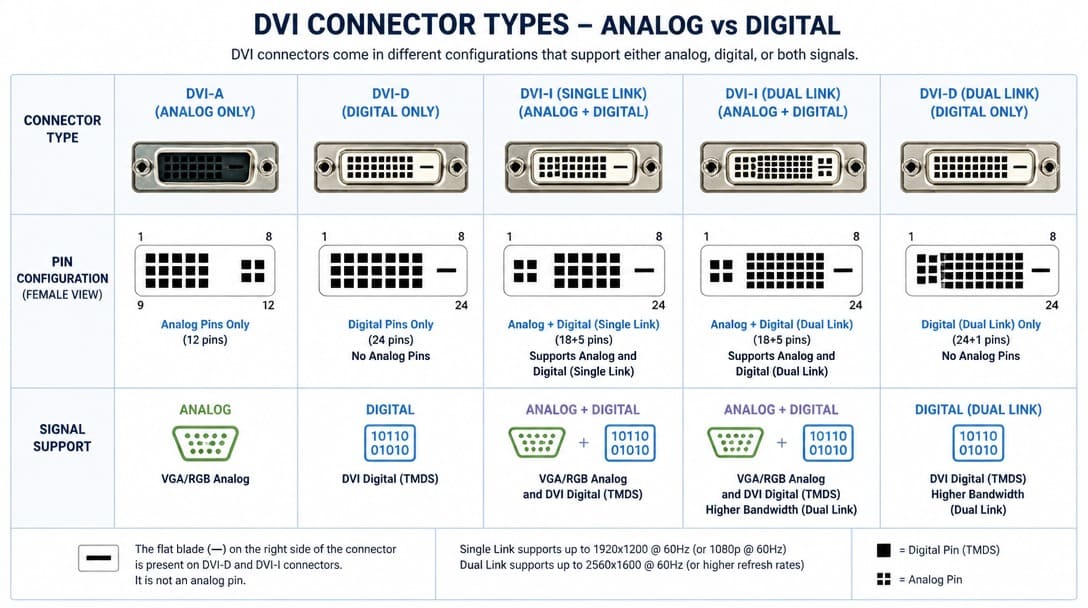
DVI connectors are grouped by signal type and bandwidth. DVI-A is analog-only and typically used where VGA-compatible signals must be carried over the same connector family. DVI-D is digital-only, available in single-link for many standard displays and dual-link for higher bandwidth or resolution requirements. DVI-I integrates both analog and digital paths, often specified when VGA backward compatibility may be needed without changing the connector footprint.
Pin count notation commonly appears as 18+1, 24+1, 18+5, and 24+5. The first number indicates signal pins; the second indicates the flat ground blade or analog group. That notation is useful for drawing review, but it does not identify the connector series, termination style, or contact plating. The table below maps the most common DVI variants for part identification.
| DVI Type | Signal Type | Common Pin Notation | Typical Use |
|---|---|---|---|
| DVI-A | Analog only | 12+5 | Legacy VGA-compatible displays, some industrial monitors |
| DVI-D single link | Digital only | 18+1 | Standard digital displays, projectors, KVM switches |
| DVI-D dual link | Digital only | 24+1 | High-resolution or high-bandwidth digital displays |
| DVI-I single link | Integrated analog + digital | 18+5 | Equipment needing VGA backward compatibility plus digital |
| DVI-I dual link | Integrated analog + digital | 24+5 | Workstations, broadcast monitors, control-room systems |
Common Industrial & OEM Application Scenarios While consumer displays have largely transitioned to HDMI and DisplayPort, DVI connectors remain widely specified in OEM and industrial environments due to their physical screw-locking capability and uncompressed video transmission:
-
Industrial Automation & HMI Panels: DVI-D (dual-link) is heavily utilized in factory control rooms, CNC machine interfaces, and KVM switches where continuous mechanical vibration requires captive thumbscrews to prevent accidental unplugging.
-
Medical Diagnostic Equipment: High-resolution medical displays, endoscopy carts, and imaging systems frequently specify DVI-I to support both legacy analog video feeds and high-bandwidth digital signals within a single housing.
-
Embedded Mainboards & Video Processing: Industrial PCs, broadcast video routers, and Automated Test Equipment (ATE) continue to integrate DVI ports to maintain backward compatibility with installed infrastructure.
Common use environments include industrial monitors, medical imaging displays, test equipment, KVM switches, digital signage, and legacy broadcast or control-room systems where replacement or custom cables remain in service. The mating face may look identical across these environments, but the downstream assembly requirements rarely are.
What a DVI Part Number Tells You — Brand, Series, and Compatible vs Interchangeable
DVI is an interface standard, not a single manufacturer product line. A part number may carry manufacturer prefixes from Molex, TE Connectivity, JST, Amphenol, or Hirose, but the same DVI interface can appear in different series with different housing, terminal, and footprint details. The prefix tells you who made the connector. It does not tell you whether that connector will drop into your board or cable tooling without process changes.
Series-specific attributes include insulator material, contact design, lead style, shield tab position, board-lock type, and terminal finish. Treating any DVI connector with the same pin count as a drop-in replacement is a common sourcing error. Two connectors can both be “DVI-D 24+1” and still have different solder tail lengths, different board-lock positions, or different shell grounding paths.
This is where the difference between compatible and interchangeable matters. A compatible connector can mate and function in the intended application. An interchangeable connector can replace another part without changing board layout, cable tooling, crimp settings, or soldering process. Many parts are compatible but not interchangeable. If the end product or cable assembly has a UL certification requirement, check whether the connector is UL recognized or listed. A connector with the same DVI interface but no UL file is not identical in a compliance-managed BOM.
Termination Compatibility: Wire Gauge, Crimp Tooling, and PCB Solder Windows
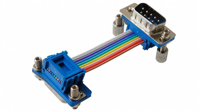
Termination type is the first hidden compatibility risk. DVI connectors can be PCB-mount or cable-mount, and cable-mount versions may be crimp-type, solder-cup, or IDC. Each requires a different production process. A drawing that only shows the mating face and pin count does not reveal which termination method the assembly line is set up to handle.
For crimp-type DVI connectors, the terminal accepts a defined wire gauge range. Using the correct wire size and matching crimp tooling is not optional. A terminal with the right mating face but the wrong wire barrel can pass visual incoming inspection but fail during crimping. The same logic applies to custom cable assemblies where the DVI connector is terminated to a prepared cable end.
For PCB-mount DVI connectors, datasheet dimensions such as pin pitch may match, but lead length, hole size, pad layout, coplanarity, and thermal mass determine whether wave, reflow, or hand soldering will produce a reliable joint. A connector optimized for reflow may not survive wave soldering without shield-tab or board-lock adjustments, even if the pin pattern looks correct.
We regularly see connectors that pass visual incoming inspection but fail during assembly — the termination interface or plating stack was engineered for a different process than the one running on the production line. The part looks right; the process doesn’t know it’s wrong.
Before ordering, confirm the assembly process: hand solder, wave, reflow, crimp, or IDC. Then verify that the connector’s termination interface matches that process. For cable-mount variants, this also means checking the wire gauge range and tooling compatibility before committing to a production batch.
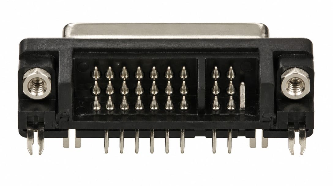
For OEM cable assembly programs, this termination check should happen during drawing review and sample confirmation, not after the first production order. Suppliers that support custom cable assembly evaluation can help verify that the connector termination matches the stated crimp and soldering process before the line is set up.
Plating Material and Thickness: The Hidden Reliability Variable
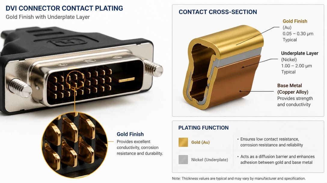
Contact plating governs contact resistance, corrosion resistance, solderability, and mating-cycle durability. A visual color match is not a specification. Gold flash and heavy gold can look identical but differ in thickness and wear behavior. Tin-lead and lead-free finishes affect process temperature and compliance, and the plating stack below the top finish controls how the contact behaves over time.
Plating choice must match the application environment. Humid industrial environments, repeated connection cycles, or long-term storage can expose insufficient plating thickness. For verification, ask for plating material, underplate, and thickness rather than relying on a datasheet appearance photo. EIA-364[1] test methods define electrical and mechanical performance expectations for connectors, and comparing connector claims against those methods is more useful than comparing product photos.
RoHS status should be confirmed for export and compliance. Not every gold or tin finish is RoHS-compliant by default. A lead-free solder process may require a specific plating stack that a leaded finish cannot support. If the product ships across borders, the plating declaration belongs in the BOM review alongside the connector part number.
Mechanical Retention: Board Locks, Shield Tabs, and Mating Latches
PCB-mount DVI connectors often rely on through-hole anchors, board locks, or shield tabs to absorb insertion and extraction force. A connector without the correct anchors can transfer mechanical stress to solder joints and fail in service. Even if the signal pins are soldered correctly, a missing board lock can cause the connector to lift from the board during repeated cable insertions.
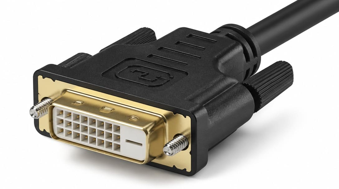
Cable-side DVI connectors use thumbscrews or friction-based retention. Thread size, panel cutout, and cable exit orientation must match the equipment. A connector that mates mechanically but has poor shield contact may pass a continuity test but fail in a noisy environment. Shield tabs and shell contact are part of the grounding and EMI path, not just mechanical convenience.
The mating interface must be fully identical: pin pattern, polarization, ground blade position, and latching features. A slightly different shell geometry may fit once but wear or disengage in the field. For wire harness manufacturers and OEM integrators, mechanical retention is often the difference between a connector that lasts one mating cycle and one that survives the product’s service life.
Connector Verification Checklist Before You Order
Use this checklist before releasing a DVI connector purchase order. Each point addresses a parameter that a generic pin-count match does not verify.
- Termination method: Confirm whether the connector is crimp-type, solder-cup, IDC, or PCB-mount. For crimp versions, verify the accepted wire gauge range and tooling. For PCB versions, confirm the soldering process and footprint tolerance.
- Plating specification: Request plating material, underplate, and thickness. Confirm the finish meets environmental, solderability, and mating-cycle requirements, and verify RoHS status for export.
- Key dimensions: Verify shell dimensions, pin length, board-lock position, coplanarity, and shield tab location with actual samples, not only datasheet drawings.
- Mating interface: Confirm the pin pattern, polarization, ground blade, shield contact, and latching or thread features are fully identical to the existing part.
For drawings, samples, or specifications that need DVI connector matching, cable assembly, and export packaging review, a source-assessment step before production reduces rework and line-down risk. Suppliers such as EDOM Electronics support OEM buyers with requirement review, connector matching, sample coordination, production follow-up, inspection, and export-ready packaging for custom cable assemblies and wire harnesses. That same verification logic extends beyond DVI to electronic connector sourcing and cable assembly, especially when a BOM mixes legacy video interfaces with current board-level interconnects.
Frequently Asked Questions
What is the difference between DVI-I and DVI-D?
DVI-I carries both analog and digital signals, while DVI-D carries digital signals only. A DVI-I connector has additional pins for the analog group, which is why its pin notation includes +5 rather than +1 for the ground blade in most single-link and dual-link configurations.
Are all DVI connectors with the same pin count interchangeable?
No. The pin count identifies the interface type, but series-specific differences in termination, board locks, plating, and shell geometry can prevent a true drop-in replacement. A connector must be verified against the board footprint and assembly process before being treated as interchangeable.
What should I check when replacing a DVI connector on a PCB?
Confirm lead length, hole size, pad layout, coplanarity, board-lock position, and shield tab location. Also verify the termination process — wave, reflow, or hand solder — and the plating stack for solderability and compliance.
Is DVI still used in industrial equipment?
Yes. DVI remains common in industrial monitors, medical imaging displays, test equipment, KVM switches, and legacy broadcast or control-room systems. Replacement and custom cable assemblies for these environments often require source verification because the original connector series may no longer be available.
How do I confirm RoHS compliance when sourcing DVI connectors?
Request a material declaration for the plating stack and insulator. Confirm that the finish is not leaded and that the supplier can provide RoHS-compliant documentation for the purchase order. Compliance cannot be assumed from part number alone.
Key Takeaways
- A DVI connector is an interface standard, not a universally interchangeable part. Pin count and mating face alone do not guarantee a working replacement.
- DVI-A, DVI-D, and DVI-I variants differ by signal type and bandwidth, with single-link and dual-link options affecting pin notation and resolution capability.
- Termination method, plating material and thickness, and mechanical retention are the three hidden parameters that dimensions do not reveal.
- Before ordering, verify termination process compatibility, plating specification, key dimensions with actual samples, and mating interface identity.
- When sourcing DVI connectors or related cable assemblies, a requirement review that covers termination, plating, and retention reduces assembly rework and field failure risk.
For electronic connector sourcing, explore electronic connector matching and supply coordination for DVI and other board-level interconnects. Many of the same verification principles apply across wire harness manufacturing and quality inspection and export packaging workflows.