Crimping JST connectors is a process of matching the exact terminal part number, wire gauge, strip length, and tool/die set to the connector manufacturer’s crimp specification — not just closing terminal wings.
For OEM buyers and production engineers, the difference between a process-controlled JST crimp and a visual-only pinching operation determines whether a cable assembly passes first-article validation or fails intermittently after installation.
JST Terminal Architecture: Two Crimps, Not One
Open-barrel JST terminals are engineered with two separated crimp zones. The conductor crimp cold-forms the stripped copper strands into a gas-tight bundle. The insulation crimp, also called insulation strain relief, grips the wire jacket without cutting into the conductor strands beneath it. These two zones have different functions and different acceptance criteria.
A correct conductor crimp shows a formed bell mouth at the rear of the crimp and a visible conductor brush — the small amount of wire extending beyond the conductor crimp zone. The insulation crimp should capture the jacket evenly without piercing it. When a technician treats the open-barrel terminal as a single pinching operation, the conductor may remain loose while the insulation is over-compressed, or the reverse.
Common JST series share this open-barrel architecture but differ in terminal height, pitch, wire range, and strip length. JST XH is widely used in 2.5 mm pitch wire-to-board connections. JST PH serves 2.0 mm pitch applications with a smaller terminal profile. JST SH, at 1.0 mm pitch, and JST ZH, at 1.5 mm pitch, are even more sensitive to strip length and crimp height because of their compact contact geometry. The conductor crimp zone in each series is designed for a defined AWG range; moving from 22 AWG to 26 AWG without changing die or strip length changes compression behavior and pull-force performance.
Tooling Decisions: OEM Crimp Tools, Generic Open-Barrel Tools, and Applicators
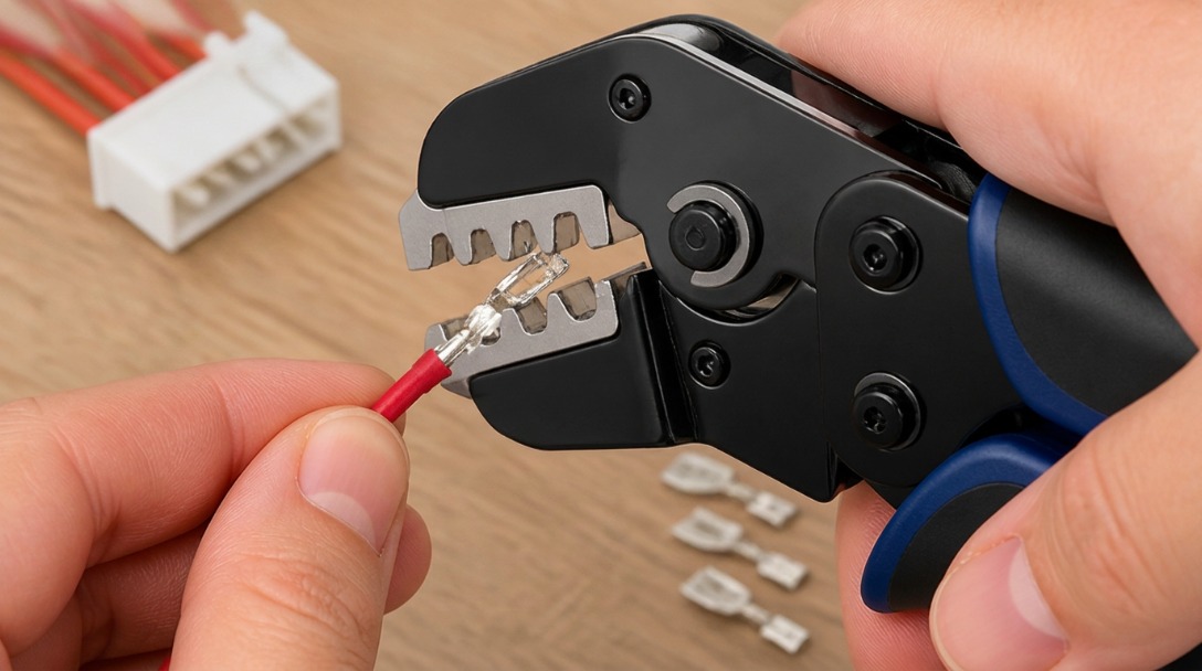
Tooling choice is the first process risk. Prototype and bench builds should use a JST OEM hand crimp tool or a ratchet tool with the correct die set for the terminal series and wire gauge. A generic open-barrel tool may close the terminal wings, but its die profile, crimp height, and terminal support can be wrong. Common results include a cracked terminal barrel, a loose conductor bundle, or wings that fold out of sequence so the conductor is only partially captured.
Low-to-mid volume builds may use a benchtop crimp press with interchangeable dies keyed to the terminal part number. Production runs often move to applicators with terminal-specific nests and adjustable crimp height. At each scale, the principle is the same: die geometry is not universal. A JST XH die set does not substitute for a JST SH or JST ZH die set simply because both are open-barrel terminals. AWG must also be verified; the same JST series may have variants for different wire gauges that require different strip lengths and crimp heights.
| Tooling Approach | Typical Scale | Die Matching | Process Control & Verification | Primary Risk |
|---|---|---|---|---|
| JST OEM hand crimp tool | Prototype, repair, low-volume | Terminal-series specific; AWG & Insulation OD dependent | Fixed ratchet release; visual check & pull testing | Tool wear or operator fatigue causing inconsistent crimps |
| Benchtop crimp press with interchangeable dies | Low-to-mid volume | Die set matched to terminal part number | Adjustable crimp height; verified by micrometer | Incorrect die installation or drift between batches |
| Automated Production Applicator | Mid-to-high volume | Terminal-specific nest | Crimp Force Monitoring (CFM) inline; Periodic Cross-Section Analysis | Setup error if terminal or wire gauge changes without revalidation |
A generic open-barrel ratchet tool belongs in none of these rows as a verified production tool, because it does not guarantee the terminal-specific die profile that JST engineering specifications require.
Step-by-Step JST Crimping Process: Strip Length to Pull-Force Verification
Repeatable JST crimping follows a sequence that begins before the first terminal is placed in the die. Each step links back to the terminal drawing or BOM.
- Confirm terminal part number, wire gauge, and strip length. Pull the JST terminal series, AWG, and strip length from the drawing or BOM. Do not strip by eye, and do not assume the same strip length works across JST XH, JST PH, JST SH, and JST ZH.
- Strip the insulation without nicking the conductor. Use a calibrated stripper or automated stripping machine. Verify that the stripped length matches the terminal drawing and that the conductor strands are intact.
- Select and verify the crimp tool or die set. Confirm that the die part number or tool marking matches the terminal series and wire gauge. If using a benchtop press or applicator, check the crimp height setting against the first-article target.
- Position the terminal in the die. Orient the open barrel so the seam and wings face the correct die profile. Close the tool partially to hold the terminal, then insert the stripped wire until the conductor brush is visible at the front of the conductor crimp zone.
- Complete the conductor crimp and insulation strain relief. Follow the sequence defined by the tool or applicator. The conductor crimp cold-forms the strands into a gas-tight bundle; the insulation crimp grips the jacket without cutting into it.
- Inspect bell mouth, conductor brush, and insulation grip. Confirm the bell mouth is formed at the crimp exit, the conductor brush is present, and no insulation has entered the conductor crimp zone.
- Measure crimp height. Use a micrometer or crimp-height gauge. Compare the reading to the JST crimp specification or IPC/WHMA-A-620[1] acceptance criteria for the terminal and wire combination.
- Perform pull-force testing and Cross-Section Analysis. Test first-article samples before inserting terminals into housings. Pull force must exceed the minimum destructive force defined in IPC/WHMA-A-620 Class 2 or Class 3. For critical OEM assemblies, a Micrograph (Cross-Section Analysis) should be performed to verify a void-free, gas-tight conductor bundle. At EDOM Electronics, our inline Crimp Force Monitors (CFM) and optical cross-section labs validate these metrics before any production batch is approved.
In wire harness production, the same sequence repeats across every branch and terminal position. A documented crimp height target and a known tool/die part number are the minimum process control records for each JST series used in the harness.
Verification Checklist and Decision Table After Crimp
Before a crimped terminal is inserted into a housing, the following checks should be completed. This is not a cosmetic review; it is the point at which a process either repeats correctly or passes a hidden defect downstream.
| Check Item | Pass Condition | Common Failure if Ignored |
|---|---|---|
| Tool/die part number | Matches JST terminal series and AWG | Conductor loose or barrel cracked on first article |
| Wire gauge | Within terminal drawing range | Over-compression or insufficient strand capture |
| Strip length | Per JST drawing or BOM | Insulation in conductor crimp or exposed conductor too long |
| Conductor placement | Fully inside conductor crimp zone; no insulation present | Partial capture, high resistance, terminal push-out |
| Insulation strain relief | Grips jacket without nicking conductor | Flex failure near terminal or cut strands |
| Bell mouth and conductor brush | Formed and visible per terminal drawing | Stress concentration at crimp exit |
| Crimp height | Measured and compared to JST spec or IPC/WHMA-A-620 | Under-crimp or over-crimp despite acceptable appearance |
| Pull force | Tested per IPC/WHMA-A-620 | Intermittent continuity or terminal detachment in service |
For OEM cable assemblies and wire harnesses that combine multiple JST series, first-article validation and process documentation become part of the sourcing decision. Suppliers such as EDOM Electronics support OEM buyers with requirement review, connector matching, sample coordination, production follow-up, inspection, and export-ready packaging for custom cable assemblies and wire harnesses. A practical sourcing review should include JST terminal part numbers, wire gauge, strip length, die selection, and acceptance criteria before full-run production begins.
JST-Specific Failure Modes and Field Consequences
Most JST crimp failures appear in the field as intermittent continuity, open circuits under vibration, terminal push-out, or corrosion at the crimp. Each failure can be traced to a specific process error.
| Failure Mode | Visual / Testing Indicator | Root Cause | Engineering Corrective Action |
|---|---|---|---|
| Under-crimp | Loose strands; Fails pull-force test | Insufficient crimp height; Undersized wire AWG | Adjust applicator crimp height downward; verify AWG match. |
| Over-crimp & Cracked barrel | Cracked barrel; Cut strands; Fails flex test | Crimp height set too low; Oversized wire | Increase crimp height; check for die wear or mismatch. |
| Insulation in Conductor Crimp | Jacket visible in conductor zone; High resistance | Strip length too short; Wire inserted too deeply | Recalibrate wire stripping machine; adjust wire stop position. |
| Missing Bell Mouth | Sharp edge at crimp exit; Wire fatigue | Misaligned terminal feed; Incorrect die tooling | Adjust terminal feed track; replace worn anvil/punch. |
| Insulation Piercing | Cut wire jacket at strain relief | Insulation OD too large for selected terminal/die | Select terminal variant designed for larger Insulation OD. |
If the JST connector is used inside a sealed enclosure, terminal crimp quality still matters. Waterproofing, as covered in How to Waterproof Connectors: Methods for OEM Cable Assemblies, does not fix a loose conductor crimp; it only prevents moisture from reaching a bad connection.
Integrating JST Crimp Requirements into OEM Production and Sourcing
Moving from a bench crimp to an OEM production run means turning the step-by-step process into documented, auditable decisions.
- First-article validation: Build samples with the specified tooling, measure crimp height, and perform pull-force testing before full-run production. A first article that passes appearance but fails measurement is not approved.
- Process control: Incoming terminal inspection, die condition checks, periodic crimp-height measurement, and pull-force sampling keep the process stable. Die wear and terminal batch changes require revalidation.
- Documentation: Record the tool/die part number, strip length, crimp height target, and operator training for each JST terminal series. When a new wire gauge or terminal series enters the BOM, the documentation updates before production resumes.
- Sourcing coordination: OEM buyers sending drawings or BOMs benefit from a connector sourcing and cable assembly partner that reviews terminal-to-connector matching, conductor crimp, insulation crimp, and acceptance criteria before production. This review should also confirm RoHS[2]-compliant terminal and housing options where export compliance matters.
Buyer’s Audit Checklist for JST Harness Suppliers: When vetting an OEM partner for wire harnesses, buyers should request specific process evidence. A reliable supplier should be able to provide:
- Documented Crimp Height (CH) and Pull-Force data logs.
- Cross-section analysis reports for first-article validation.
- Confirmation of Crimp Force Monitoring (CFM) on automated lines.
- Traceability connecting specific JST die part numbers to production batches.
Final inspection and export packaging should follow the same documentation discipline as crimp height measurement. A correctly crimped terminal still needs packaging that protects terminal alignment, conductor brush, and housing mating surfaces during shipment.
Related Connector Assembly Guides and Waterproofing Context
JST crimp quality is only one layer of a larger connector assembly decision. When the same terminal is used inside a sealed device, the crimp remains the primary electrical and mechanical interface; sealing methods are secondary to a good crimp. For broader waterproofing methods, refer back to the overview at How to Waterproof Connectors: Methods for OEM Cable Assemblies.
For OEM connector sourcing, terminal processing, and cable assembly support, explore electronic connector sourcing and terminal processing support.
Frequently Asked Questions
Can I use a generic open-barrel crimp tool for JST connectors?
A generic tool may close the terminal wings, but JST terminal geometry is matched to specific die profiles and crimp heights. Without the correct die set for the terminal series and AWG, the conductor can be loose, the barrel can crack, or the insulation crimp can be over-compressed. OEM hand tools, benchtop presses with matched dies, or production applicators are preferred.
What is the correct strip length for JST XH, PH, SH, and ZH terminals?
There is no single correct strip length. Each JST terminal drawing specifies the strip length for the intended wire gauge and terminal series. JST SH and JST ZH use shorter, more compact crimp zones than JST XH or JST PH, so strip length must be confirmed from the BOM or terminal datasheet before stripping.
How do I measure crimp height on a JST terminal?
Crimp height is measured across the compressed conductor crimp zone with a micrometer or crimp-height gauge. The reading must be compared to the JST crimp specification for that terminal and AWG, or to IPC/WHMA-A-620 acceptance criteria. A visual check alone does not verify crimp height.
What is the difference between the conductor crimp and insulation crimp?
The conductor crimp cold-forms stripped copper strands into a gas-tight electrical and mechanical connection. The insulation crimp, also called insulation strain relief, grips the wire jacket to support the wire and prevent flex stress from reaching the conductor crimp. Both zones have separate acceptance features such as bell mouth, conductor brush, and jacket grip.
Do JST connectors require pull-force testing?
For OEM and wire harness production, first-article samples should undergo pull-force testing according to IPC/WHMA-A-620. Pull force verifies that the conductor crimp has achieved sufficient mechanical capture. A terminal that passes visual inspection but fails pull force is not production-ready.
Key Takeaways
- JST open-barrel terminals require two distinct crimps: the conductor crimp and the insulation crimp, each with specific acceptance features.
- Tooling must match the exact JST terminal series and AWG; generic open-barrel tools cannot substitute for terminal-specific die profiles.
- Strip length, terminal orientation, bell mouth, conductor brush, and crimp height must be verified against the JST drawing and IPC/WHMA-A-620 criteria.
- Under-crimp, over-crimp, cracked barrels, and insulation in the conductor crimp can pass visual checks but fail in the field.
- OEM sourcing for JST cable assemblies should include first-article validation, process documentation, and export-ready inspection.