Direct Answer: What the DE 9 Name Actually Tells You
The DE 9 designation comes from the D-subminiature connector family. The letter “E” refers to the shell size, and the number 9 refers to the number of positions. Many drawings still label the part as DB9, but that is a common misnomer; the B shell size corresponds to a 25-position configuration, while the E shell size is used for the 9-position layout.
What the name does not tell you is more important for sourcing. A DE 9 connector from Molex, TE Connectivity, JST, Amphenol, or Hirose may share the same shell outline, but each brand and series adds its own termination options, plating specifications, mounting hardware, and accessory ecosystem. Two parts that look identical on an outline drawing can have different crimp tooling requirements, different through-hole layout tolerances, or different mating retention mechanisms.
For the broader electrical, mechanical, and environmental roles any connector must satisfy, the pillar overview at what is a connector (see our practical overview for OEM buyers) provides the foundation. This article focuses on the DE 9-specific sourcing risks that shell size alone does not reveal.
Standard DE 9 Pinout Configurations (RS-232 & CAN Bus)
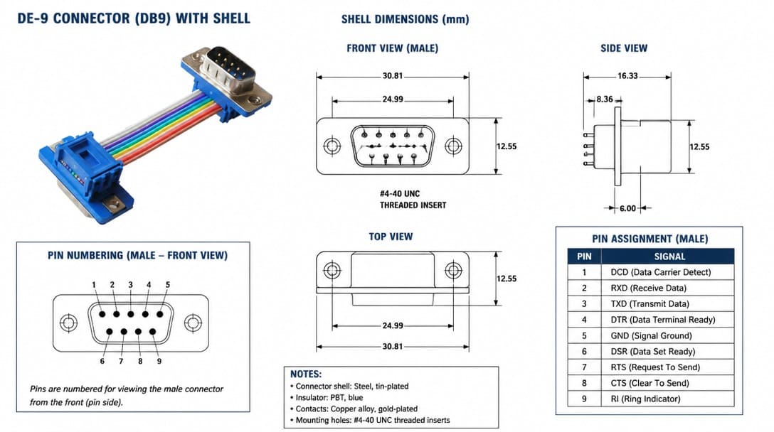
While the DE-9 connector is a hardware standard, its pinout depends entirely on the communication protocol it carries. Below are the two most common industrial applications: RS-232 and CAN bus.
RS-232 Pinout (Standard EIA/TIA-232)
When used for serial communication, the DE-9 connector follows a strict pinout. It is crucial to note that the TxD and RxD pins are swapped depending on whether the device is DTE (Data Terminal Equipment, like a PC) or DCE (Data Circuit-terminating Equipment, like a modem).
CRITICAL WIRING NOTE: Pinout numbering is mirrored between male (plug) and female (receptacle) connectors. When viewing the mating face of a male connector, Pin 1 is at the top left. On a female connector mating face, Pin 1 is at the top right. Always verify if your schematic specifies a front mating view or a rear solder/crimp view to avoid reversed wiring.
Pro Tip for OEM Cost Reduction: While standard RS-232 has 9 pins, many custom B2B applications only require a 3-wire null modem configuration: Pin 2 (RxD), Pin 3 (TxD), and Pin 5 (GND). Omitting unneeded wires and contacts reduces raw material costs and assembly labor.
| Pin # | Signal (DTE) | Description |
|---|---|---|
| 1 | DCD | Data Carrier Detect |
| 2 | RxD | Receive Data |
| 3 | TxD | Transmit Data |
| 4 | DTR | Data Terminal Ready |
| 5 | GND | Signal Ground |
| 6 | DSR | Data Set Ready |
| 7 | RTS | Request To Send |
| 8 | CTS | Clear To Send |
| 9 | RI | Ring Indicator |
CAN Bus Pinout (Standard CiA 303-1)
In industrial automation and automotive testing, the DE-9 is the defacto standard for CAN bus nodes.
| Pin # | Signal | Description |
|---|---|---|
| 2 | CAN_L | CAN Low bus line |
| 3 | GND | CAN Ground |
| 7 | CAN_H | CAN High bus line |
| 9 | V+ | Optional CAN external supply |
| (Pins 1, 4, 5, 6, and 8 are typically reserved or unused in standard CAN applications). |
The Hidden Compliance Gate: Termination Compatibility
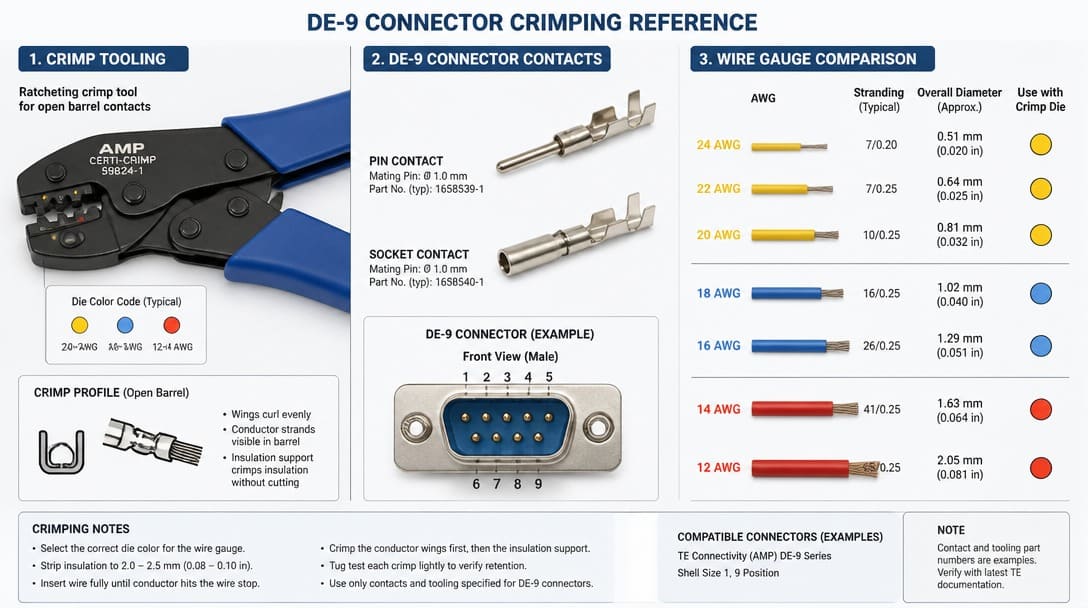
Matching the DE 9 shell outline does not confirm whether the connector terminates by solder cup, crimp contact, insulation displacement, or PCB pin. Each termination method has its own process window and design constraints.
- Solder cup: expects discrete wires to be inserted into cups and soldered. The cup diameter and wire strip length must be compatible with the conductor size and the production soldering equipment.
- Crimp contacts: require a specific wire gauge range. A DE 9 contact body sized for 20–24 AWG conductors will not produce a reliable crimp on 26 or 28 AWG wire, even if the contact physically fits into the housing.
- PCB mount: requires through-hole lead spacing, hole diameter, standoff height, and pad layout to match the board. The soldering process window — wave, selective, or hand soldering — must also be considered.
We regularly see connectors that pass visual incoming inspection but fail during assembly — the termination interface or plating stack was engineered for a different process than the one running on the production line. The part looks right; the process doesn’t know it’s wrong.
For OEM buyers integrating DE 9 connectors into custom cable assemblies or wire harnesses, termination compatibility should be confirmed on the first article sample, not discovered on the production line.
Plating and Contact Reliability: What “Looks Compatible” Won’t Show
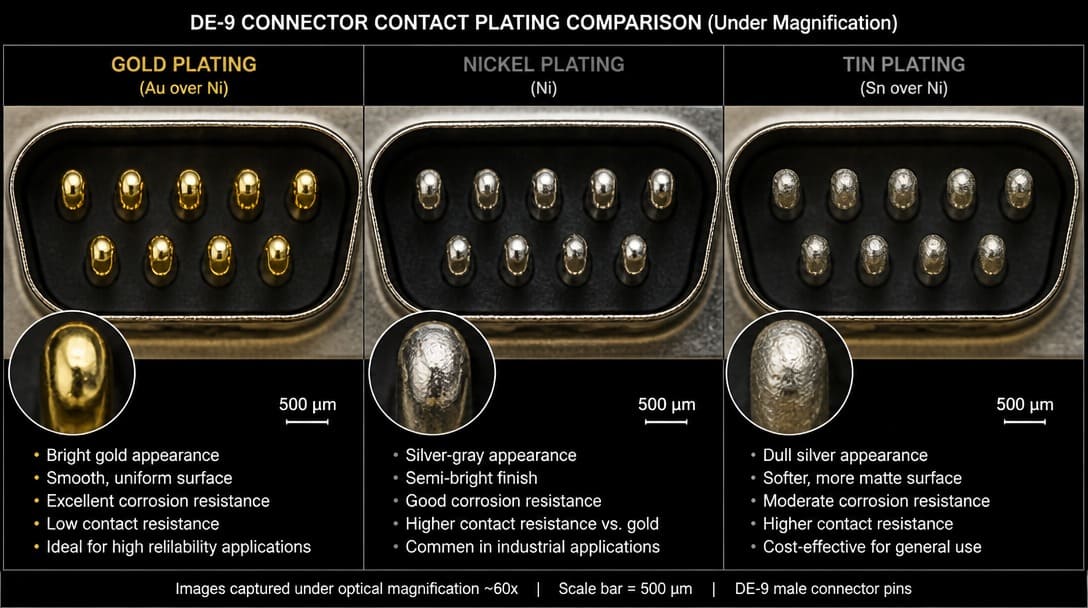
Plating material and thickness govern contact resistance, corrosion resistance, solderability, and real mating cycle life. An outline drawing rarely communicates the plating stack. What the eye sees on a gold-colored contact says nothing about the thickness of the gold layer, the presence of a nickel underplate, or the type of gold plating used.
Gold flash, selective gold, and tin plating behave differently in dry circuit, humid, high-vibration, or repeated-mating applications. Buyers should compare the full plating stack — not just the top layer. A tin-plated contact may be cost-effective for a single insertion in a dry environment but can develop contact resistance problems in a humid atmosphere or when mated and unmated repeatedly.
RoHS[1]-compliant plating options can shift contact performance, so confirm the supplier’s plating specification matches the mating half and the operating environment. When comparing datasheet claims from different brands, EIA-364 test methods for contact resistance, mating durability, and environmental exposure provide a useful reference. Ask the supplier which test method was used to qualify the plating, not just what the data sheet says.
| Plating Option | Typical Use | Sourcing Consideration |
|---|---|---|
| Gold flash (1-3 µ”) over nickel | Low-cost general purpose, < 50 mating cycles | Verify gold thickness. Unsuitable for high-vibration industrial environments. |
| 15 µ” Gold over nickel | Commercial/Industrial equipment, up to 200 mating cycles | Standard balance of cost and reliability. Confirm selective coverage area. |
| 30 µ” Gold over nickel | Harsh environments, military/medical, > 500 mating cycles | Confirm plating thickness test method (EIA-364) and require independent material testing reports. |
| Tin over nickel | Cost-sensitive, < 25 insertion frequency | Tin oxidizes and suffers from fretting corrosion. Only use in static, dry circuits. |
Mechanical Retention: Board Locks, Jackscrews, and Thread Standards
A DE 9 connector’s mechanical retention is not defined by shell size. Board locks, through-hole anchors, clinch nuts, jack screws, and latch features vary by series and brand. Two connectors with the same shell outline can have entirely different mounting footprints.
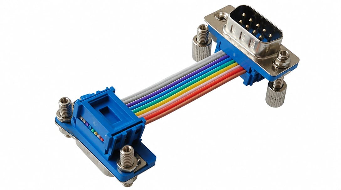
The Jackscrew Thread Trap (4-40 UNC vs. M3): Mating retention hardware such as jack screws must pair correctly with the mating half and the panel cutout. A frequent sourcing error is mixing standard US 4-40 UNC threads (the industry default for D-subs) with metric M3 threads. A mismatched jackscrew will cross-thread, prevent full engagement, or loosen in service, even when the shell dimensions match perfectly. Buyers should specify thread type explicitly on the BOM.
Board-mount retention features determine whether the connector survives PCB handling, cable strain, and field vibration. Through-hole anchors may be required for a robust mount, especially when the connector is subjected to repeated cable pull or is mounted on a board that experiences mechanical shock. If the board has no corresponding anchor hole, the connector may not seat properly even if the main pin pattern aligns.
Mating retention hardware such as jack screws must pair correctly with the mating half and the panel cutout. A jack screw with the wrong thread pitch or length will prevent full engagement or loosen in service, even when the shell dimensions match. Buyers should specify jackscrew type, thread, and standoff height explicitly rather than assuming the standard product includes the correct hardware.
Compatible vs Interchangeable: The Sourcing Risk Nobody Labels on the Quote
“Compatible” and “interchangeable” are often used interchangeably in sourcing conversations, but they describe different outcomes. A compatible part can be made to work in the target application with acceptable performance after some adjustment. An interchangeable part is a drop-in equivalent that requires no process, footprint, tooling, or requalification changes.
Cross-brand DE 9 connectors from Molex, TE Connectivity, JST, Amphenol, and Hirose may share the shell outline but differ in termination, plating, retention hardware, and available accessories. Treating a catalog equivalent as interchangeable without checking terminal tooling, PCB footprint, plating callout, and mating hardware is a common source of last-minute rework.
| Criterion | Compatible | Interchangeable |
|---|---|---|
| Termination method | May require different tooling or process change | Same termination style and wire range |
| PCB footprint | Pad layout or hole diameter may differ | Identical footprint and standoff |
| Plating stack | Equivalent performance but different specific materials | Same plating callout and thickness |
| Mating hardware | May require adapter or different jackscrew | Same thread, length, and retention |
| Qualification status | Requires requalification or sample approval | Can be dropped into existing BOM |
Decision rule: if any process or qualification document must change, the part is compatible — not interchangeable. That distinction should appear in the sourcing decision, not after the first production run.
DE 9 Connector Verification Checklist Before You Order
Before requesting a quote or sample, verify the following on the specific part number, not just the generic shell type:
- Termination method: Confirm whether the connector terminates by solder cup, crimp, IDC, or PCB mount. Check wire gauge range for crimp contacts, cup diameter for solder cups, and footprint for PCB-mount types.
- Plating specification: Confirm the full plating stack — gold flash, selective gold, or tin over nickel — meets environmental and mating-cycle requirements, including RoHS status and any EIA-364 test evidence the supplier can provide.
- Key dimensions: Verify with actual samples, not just datasheet drawings: shell height, flange hole pattern, lead length, boardlock position, and mating interface.
- Mating interface: Confirm pin arrangement, shell grounding, jackscrew threading, and retention hardware are fully identical, not just the connector body outline.
- Material and rating documentation: If the assembly carries a UL requirement, check for UL component recognition or listing data and plastic flammability rating.
If you are comparing DE 9 connector alternatives, request a sample-level review of termination, plating, and retention before committing to a production order. Suppliers such as EDOM Electronics support OEM buyers with requirement review, connector matching, sample coordination, production follow-up, inspection, and export-ready packaging for custom cable assemblies and wire harnesses. This type of review is especially useful when the BOM includes a legacy DE 9 part that may have been specified years ago for a process that no longer exists on the line.
For teams that also need incoming inspection and export packaging support, confirming these details before shipping prevents cross-border quality disputes and line stoppages.
From Design to Manufacturing: Sourcing DE 9 for Custom Cable Assemblies
Identifying the right DE-9 connector on paper is only half the process. Transitioning from a part number to a stable supply requires matching the connector to the actual manufacturing process—especially when overmolding (injection molding) or EMI/RFI shielded metal hoods are involved.
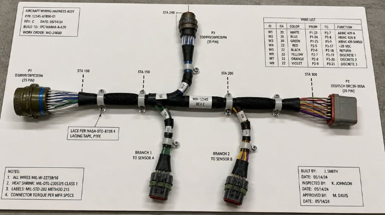
As an operation adhering to IPC/WHMA-A-620 standard practices, EDOM Electronics offers rigorous cross-reference engineering. We review your exact pinout, termination method, and environmental requirements. For example, we cross-check your specified wire gauge against terminal barrel capacities to prevent hidden pull-force failures on the production line, providing direct drop-in equivalents that reduce lead times.
If you are dealing with legacy DB9/DE 9 drawings or experiencing supply chain bottlenecks with brands like Molex or TE Connectivity, EDOM Electronics offers cross-reference engineering. We review your exact pinout, termination method, and environmental requirements to provide direct drop-in equivalents, helping you reduce lead times while maintaining MIL-DTL-24308 or commercial standard compliance.
Ready to verify your BOM? Send us your wiring diagram or current part numbers for a free Design for Manufacturing (DFM) review and connector matching analysis.
Frequently Asked Questions
Is a DE 9 connector the same as a DB9?
No. DB9 is a common misnomer. The correct D-subminiature designation for a 9-position shell is DE 9. The letter refers to shell size: B is 25 positions, E is 9 positions. Many drawings still use DB9 out of habit, but the shell size E is what matters for sourcing.
Can I replace a Molex DE 9 connector with a TE Connectivity or JST part if the pin count matches?
Not automatically. The shell outline and pin count may match, but termination style, wire gauge range, plating stack, PCB footprint, and jackscrew threading can differ. You need to verify the part is interchangeable, not just compatible.
What is the most common overspecification mistake when buying DE 9 connectors?
The most common mistake is matching the physical dimensions and pin count while ignoring the termination interface. A crimp contact sized for 20–24 AWG will not crimp reliably on 26 AWG wire, and a PCB-mount footprint may not match the board’s hole pattern or soldering process.
Does a DE 9 connector need to be RoHS compliant?
If the final product is sold into markets requiring RoHS compliance, the connector plating and materials must be RoHS compliant. RoHS-compliant finishes can behave differently than traditional tin-lead finishes, so confirm the plating specification matches the mating half and the operating environment.
Should I ask for a sample before placing a production order for DE 9 connectors?
Yes. A sample-level review of termination, plating, and retention hardware is the most reliable way to confirm that the part will work in the actual assembly process. Datasheet drawings do not reveal process compatibility or plating stack details.
Key Takeaways
- DE 9 identifies a D-subminiature shell size and 9-position pin count — not a brand, series, termination, plating, or retention specification.
- Termination compatibility (solder cup, crimp, PCB) and plating stack are the two most common sources of assembly-time failure that visual inspection misses.
- “Compatible” and “interchangeable” are different sourcing outcomes; if any process, footprint, or qualification document must change, the part is only compatible.
- Verify key dimensions, mating hardware, and plating with physical samples before committing to a production order.
- Brand-specific DE 9 connectors from Molex, TE Connectivity, JST, Amphenol, and Hirose require supplier-level confirmation of the full specification, not just the shell drawing.
For DE 9 connector sourcing and cable assembly review, explore electronic connector options to move from part identification to sample confirmation and stable supply.