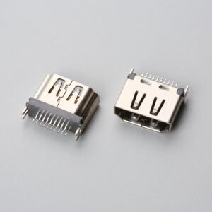
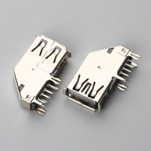
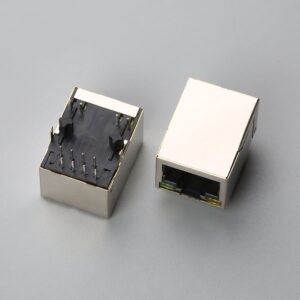
Medical cable assemblies are application-specific interconnect systems that transmit power, signals, or both between medical equipment and patient interfaces, with shielding, insulation, overmolding, and compliance characteristics selected for reusable, disposable, or hybrid patient-monitoring, diagnostic, and surgical equipment.
Is the Cable Assembly the Root Cause? Opening the Field Failure Report
The design review starts at an engineer’s desk with a field failure report: intermittent ECG/SpO2 signal dropouts that occur only when the patient moves. Bench continuity passes. The cable pinout matches the bill of materials. Yet the device still fails in use. This pattern usually means the original specification treated the cable assembly as a simple extension of the connector, not as a mechanical and electromagnetic system that flexes, bends, and is exposed to disinfection chemistry. Pinout and continuity checks confirm conductor order, but they do not evaluate flex life, shield termination, jacket material, or strain relief performance. A defensible cable construction choice must therefore be made before the next build, not after the field return. The sections that follow move through the type decision, overmolding versus mechanical assembly, shielding and jacket selection, IEC 60601-1 leakage current constraints, IPC/WHMA-A-620 acceptance classes, and a go/no-go checklist that can be applied during vendor drawing review and sample confirmation.
Which Medical Cable Assembly Type Fits Reusable, Disposable, or Hybrid Patient-Monitoring Designs?
The first decision is architectural: will the assembly be reused, disposed of after patient use, or split into a hybrid design? Each choice changes service life, sterilization exposure, connector mating cycles, and cost-per-procedure logic.
| Parameter | Reusable Cable Assembly | Disposable Cable Assembly | Hybrid Cable Assembly |
|---|---|---|---|
| Service life | Designed for multiple reprocessing cycles | Single-patient or limited-use | Reusable trunk with limited-use patient-contact lead |
| Sterilization or disinfection exposure | Autoclave, chemical disinfection, or both | Minimal or none | Depends on the reusable portion |
| Connector mating cycles | Higher cycle requirement | Lower cycle requirement | Split between trunk and lead |
| Cost logic | Higher unit cost amortized over procedures | Lower unit cost balanced by replacement volume | Middle-ground cost per procedure |
| Primary clinical driver | Imaging, surgery, or repeated monitoring | Infection control and single-use workflow | Reduce waste without sacrificing durability |
In reusable patient-monitoring leads, overmolding often pays off in autoclavable or chemical-disinfection environments because the termination must survive repeated connector mating and cleaning. A disposable assembly shifts the economic calculation from initial unit cost to cost per procedure and removes cross-contamination and reprocessing risk. Hybrid designs combine a durable reusable trunk with a limited-use patient-contact branch, balancing front-end cost and clinical workflow. TPE and silicone are common first-pass jacket choices for reusable flex life and patient-contact safety. TPE provides good flex fatigue and dimensional stability, especially against quaternary ammonium and bleach disinfectants, while silicone offers high heat tolerance for repeated steam autoclaving (121°C/134°C) and softness for patient contact, though with lower tear resistance and vulnerability to aggressive alcohol wipes.
Overmolded vs. Mechanical Assembly: Which Construction Decision Reduces Field Risk?
Overmolding creates a continuous molded boot around the cable-to-connector junction, bonding the jacket, cable bundle, and connector body into a single strain-relief zone. Mechanical assembly uses a backshell, clamp, or gland that compresses the cable and adds a separate strain-relief component. Each approach changes how failure occurs.
Overmolding tends to improve flex endurance at the termination because it distributes bending stress over a longer transition zone and reduces particulate gaps where fluids or cleaning agents can collect. It also improves ingress protection(see Waterproof Cable Assembly Manufacturing & Supply for OEM Buyers) and cable retention, but it makes rework more difficult because the termination cannot be easily disassembled. Mechanical assembly enables rework and field replacement of individual components, but it introduces additional interfaces that can loosen, trap contamination, or concentrate bending at the clamp edge. Patient-monitor failure modes often begin at the termination rather than mid-cable. When a lead drops out only during patient movement, the strain relief and shield termination near the connector are the first places to inspect. For high-movement ECG and SpO2 leads, an overmolded strain relief is usually the lower-risk choice, provided the internal conductors and shield are also supported before the molding operation.
Which Shield Termination and Jacket Combination Protects Signal Integrity and Service Life?
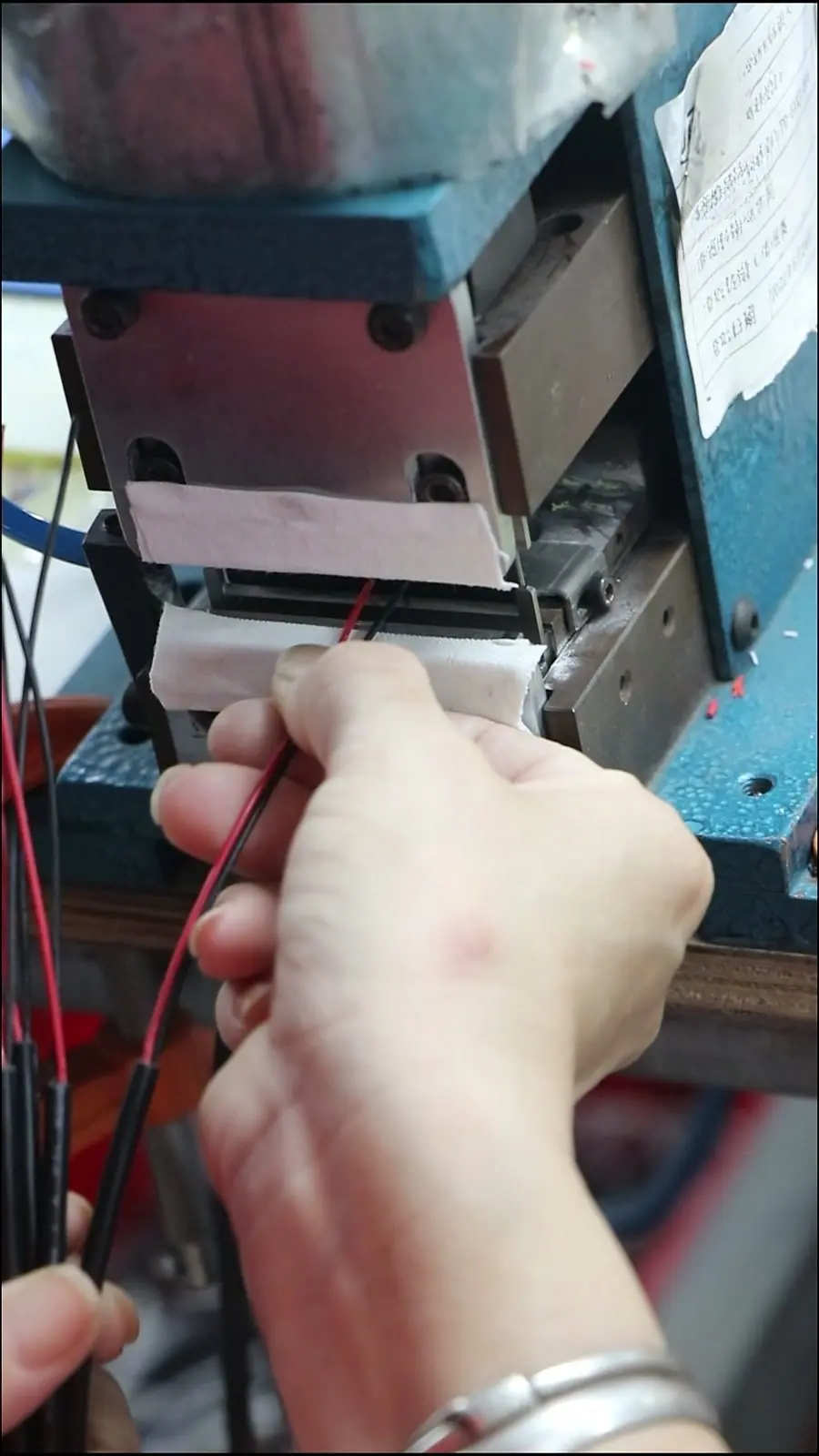
A wrapped or spiral shield that is not terminated to the connector shell or grounding circuit behaves as a floating conductor. It may pass a simple continuity check because the shield braid has physical continuity along its length, but without a low-impedance termination at one or both ends, it cannot route common-mode noise to ground. In patient monitoring, that failure mode often appears as intermittent ECG artifact or SpO2 signal dropout when the patient leans or the cable moves against bedding. EMI shielding effectiveness therefore depends on the shield drain path and termination method—crimped drain wire, connector backshell bonding, or overmold-encapsulated termination—not on the presence of a shield wrap alone.
In sensitive electrophysiological applications (e.g., ECG/EEG), motion artifacts are frequently induced by the triboelectric effect between moving conductors and dielectric insulation. High-grade medical assemblies mitigate this by incorporating a semi-conductive carbon layer or conductive tape beneath the braided shield to bleed off electrostatic charges.
Jacket choice adds a second boundary. TPE typically offers good flex fatigue, resistance to many cleaning agents, and a consistent tactile feel, but aggressive disinfectants can eventually harden or crack certain TPE grades. Silicone withstands high temperatures and offers softness for patient contact, including autoclavable reusable designs, but has lower tear resistance and can be cut by sharp strain-relief edges. For a moving patient-monitor lead, the jacket must survive both repeated flexing and the facility’s disinfection protocol. Shield coverage, drain-wire placement, and jacket bonding together determine whether the assembly maintains signal integrity after repeated movement cycles and cleaning exposures.
What Do IEC 60601-1 Leakage Current and IPC/WHMA-A-620 Class Change in the Go/No-Go Criteria?
IEC 60601-1 electrical safety requirements for medical equipment influence cable design before the first continuity test is performed. Patient-applied parts and patient connections must meet leakage current limits that affect insulation dielectric strength, thickness through insulation, and connector contact creepage/clearance distances to satisfy MOPP (Means of Patient Protection) requirements. A cable that passes continuity but uses insulation with insufficient dielectric strength or excessive creepage can still exceed leakage limits under fault conditions. For a patient-monitor cable, the insulation system is a safety boundary, not just a cosmetic layer.
IPC/WHMA-A-620 adds process and acceptance discipline(see What to Know About Medical Cable Assembly Manufacturing Standards). It defines three workmanship classes for cable and wire harness assemblies, with Class 1 for general electronic products, Class 2 for dedicated-service products, and Class 3 for products where performance or the environment demands the highest assurance. For medical patient monitoring, critical leads generally push toward Class 3 because acceptable crimp deformation, insulation clearance, and shield termination inspection become tighter than in Class 2. Class 3 criteria change the pass/fail decision: a marginal crimp that might be acceptable in Class 2 can be rejectable in Class 3 because of stricter limits on conductor damage and insulation support.
ISO 13485 supplier quality expectations(see How Manufacturers Ensure Consistent Cable Assembly Quality?) also enter the vendor conversation when the go/no-go criteria are translated into a controlled drawing. Under ISO 13485, drawing changes, material substitutions, and process changes should be documented, reviewed, and traceable, because a silent insulation change can shift leakage current or cleaning compatibility without changing the part number.

Medical Cable Assembly Go/No-Go Design Checklist: Conductor, Insulation, Shield, Strain Relief, IPC Class
The following table is structured for direct screenshot capture during vendor review. If any field returns a no-go trigger, the assembly should not pass design release until the drawing, material callout, or termination method is corrected.
| Checklist Field | Go Condition | No-Go Trigger |
|---|---|---|
| Conductor size and flex rating | Conductor gauge and strand count specified for expected flex life; insulation rated for applied voltage and movement | Solid or insufficiently stranded conductor with no flex rating; conductor size chosen only by current capacity |
| Insulation system and material | Insulation material compatible with disinfectant and patient-contact requirements; thickness supports IEC 60601-1 leakage and creepage | Unspecified insulation grade; wall thickness based on commercial cable without medical safety verification |
| Shield termination method | Shield drain path terminated at connector ground; shield coverage specified; no floating shield | Shield present but not terminated; drain wire left unconnected; shield path not inspectable |
| Strain relief type | Overmolded or mechanically clamped strain relief that extends past the flex point; bend radius supported | Strain relief ends before the flex point; sharp transition at connector; boot hides unsupported conductors |
| IPC/WHMA-A-620 class | Class 3 for critical patient-monitor leads with movement; Class 2 only where documented and acceptable | No acceptance class defined on drawing; crimp and shield criteria left to supplier default |
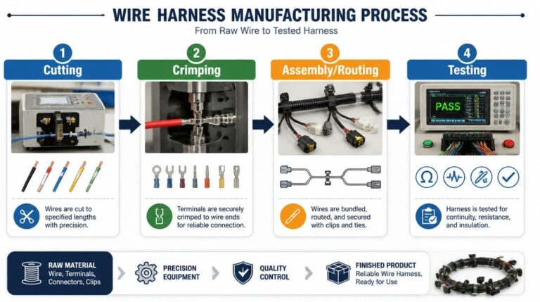
IEC 60601-1 leakage current becomes the pass/fail boundary behind the insulation and creepage entries: a conductor that passes continuity but uses unqualified insulation cannot meet the safety case. For multi-branch harnesses that carry multiple leads from patient monitors, these criteria extend into routing, labeling, looming, and continuity verification practices covered in the wire harness manufacturing overview.
What Goes Wrong in the Field: Failures That Pass Continuity but Fail in Patient Use
Field returns reveal four recurring failure modes that bench continuity does not catch.
- Floating shields: the conductor circuit remains intact, but the shield is not terminated to ground. Continuity testing on the signal path passes, while EMI shielding effectiveness collapses and patient movement introduces noise that appears as intermittent ECG artifact or SpO2 dropout.
- Insulation micro-damage: a conductor may be intact but the insulation has a crack or micro-puncture that has not yet exposed copper. Continuity passes because the current path is unchanged, but leakage current or moisture ingress becomes a risk under patient use.
- Strain relief failures: the overmold boot or mechanical clamp may look intact, but internal conductor strands begin to break under repeated flexing at the transition. Intermittent opens occur only with movement, so a static continuity test will pass.
- Disinfectant-induced jacket cracking: aggressive cleaning agents can degrade TPE or other jacket materials, creating surface cracks that do not immediately reach the conductors. The unit passes continuity, but subsequent flexing and cleaning cycles propagate the crack until insulation failure occurs.
Each failure mode is tied to construction choices. TPE can crack with repeated aggressive disinfectant exposure; silicone may tear at sharp strain-relief edges or abrasion points; and overmolded boots can hide flex failures if internal strain relief is not provided. The recurring insight is that field returns from patient movement are a better predictor of cable reliability than static acceptance testing alone. A design review should simulate motion, disinfection exposure, and cable routing before locking the specification.
Which Material and Compliance Boundaries Drive the Vendor Conversation?
When the engineering review moves to sourcing, the material boundary conditions should already be visible on the drawing. Patient-contact materials may require biocompatibility assessment under ISO 10993. While raw material suppliers frequently cite USP Class VI as an initial screening indicator, finished patient-contact cables must be evaluated under the full ISO 10993 framework—specifically assessing cytotoxicity (ISO 10993-5), sensitization, and intracutaneous reactivity (ISO 10993-10) on the finished, post-sterilization assembly. Autoclavable reusable assemblies add a thermal and moisture boundary: the jacket, adhesive, and overmold compound must survive repeated steam sterilization without delamination or hardening. TPE and silicone remain the primary trade-off pair—TPE for flex fatigue and cleaning-agent compatibility, silicone for heat tolerance and patient-contact softness—but the final choice depends on the facility’s reprocessing and disinfection protocol.
The compliance framework, including ISO 13485 supplier quality expectations, IEC 60601-1 leakage current constraints, and IPC/WHMA-A-620 acceptance classes, should appear as folder-level requirements in the RFQ, not afterthoughts appended after a supplier has quoted. A vendor-ready package typically includes the field failure report or design context, the controlled cable drawing, target quantities and delivery windows, packaging and shipping expectations, and the completed go/no-go checklist. To minimize NRE tooling costs and regulatory risk during prototyping, OEM engineering teams should partner with interconnect manufacturers capable of rapid modular mold inserts for overmolds, providing pre-validated biocompatible compounds, and delivering complete DFM (Design for Manufacturability) packages alongside 3-5 day functional prototypes. For projects that also include export logistics, inspection documentation and packaging standards are covered in the quality inspection and export packaging resource. Cost-down discussions are a separate downstream decision: they should begin only after electrical safety, mechanical reliability, and material boundaries are locked, because substituting a cheaper jacket or termination method without documented change control can reintroduce the field failure that started the review.
Frequently Asked Questions
What is the difference between a medical cable assembly and a standard cable assembly?
A medical cable assembly is designed and documented for medical device safety and clinical use. It typically requires IEC 60601-1 leakage current considerations, biocompatibility or USP Class VI material review, disinfection compatibility, and often IPC/WHMA-A-620 Class 3 acceptance criteria. A standard commercial cable may meet electrical continuity but lacks the safety and documentation boundary for patient-applied use.
Which jacket material is better for reusable patient-monitoring cables: TPE or silicone?
The answer depends on the sterilization or disinfection protocol and the flex environment. TPE tends to offer good flex fatigue and cleaning-agent resistance. Silicone provides high-temperature tolerance and softness for patient contact and is often suitable for autoclavable designs, but it has lower tear resistance. The decision should be validated against the facility’s actual cleaning agents and movement profile.
Does a cable assembly that passes continuity testing meet IPC/WHMA-A-620 Class 3?
No. Continuity confirms conductor paths, but IPC/WHMA-A-620 Class 3 imposes additional acceptance criteria on crimp deformation, insulation clearance, shield termination, and documentation. A continuity-passing assembly can still fail Class 3 inspection if strain relief, insulation support, or shield termination do not meet the tighter requirements.
When should an overmolded medical cable assembly be specified instead of a mechanical backshell?
Overmolding is usually preferred for high-movement patient leads where termination flex fatigue, ingress protection, and smooth cleanability matter. Mechanical assembly is preferable for repairability or mixed-configuration prototypes. The decision should be based on field failure mode, cleaning exposure, and production strategy.
What documents should an OEM buyer send when requesting a medical cable assembly quote?
Provide the cable drawing, connector types and mating devices, target quantities, packaging and shipping expectations, the compliance folder, and the completed go/no-go checklist. Include the field failure report or known failure mode if available. This context helps the supplier evaluate materials, overmolding, crimping, inspection, and export packaging before quotation.
Key Takeaways
- Medical cable assemblies are not defined by continuity alone. Pinout and conductor checks miss shield termination, flex life, insulation safety, and strain relief failures.
- Architecture choice—reusable, disposable, or hybrid—determines cleaning exposure, cost-per-procedure, and connector mating cycles before material selection begins.
- Overmolding reduces termination flex risk and ingress paths but adds rework constraints, while mechanical assembly favors repairability but introduces extra interfaces.
- Shield termination, jacket material selection, and disinfection compatibility determine signal integrity and service life under patient movement.
- IEC 60601-1 leakage current requirements and IPC/WHMA-A-620 acceptance classes create pass/fail boundaries that should be locked in the drawing before sourcing.
For OEM teams that need a vendor-ready path from drawing review to sample confirmation, connector matching, overmolding coordination, and export packaging, explore custom cable assembly solutions that align with medical safety and inspection requirements.