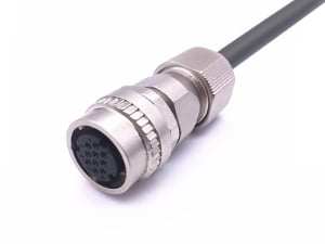
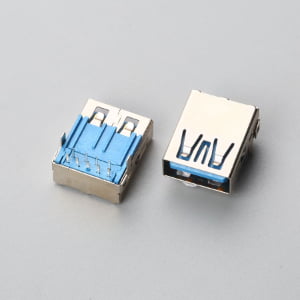
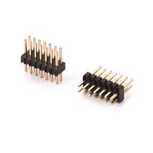
When evaluating gold vs tin contact resistance for electrical connectors, the primary difference lies in surface oxide stability: gold is a noble metal that does not oxidize, providing a low, stable contact resistance (<10–20 mΩ) across its operating life; tin forms a natural, non-conductive tin oxide (SnO₂) surface layer that requires mechanical wiping and sufficient contact force (≥100 g) to displace and establish reliable metal-to-metal continuity.
Two procurement scenarios typically drive this evaluation: an intermittent signal failure in a field return, or a cost-reduction proposal to downgrade a bill of materials (BOM) from gold to tin. (See our background guide: What Is a Connector? A Practical Overview for OEM Buyers).
How to Compare Gold vs Tin Contact Resistance for OEM Connectors
Step 1: Classify the Trigger—Field Return or Cost-Cutting Request
Start by classifying the problem before comparing milliohm values. If the trigger is an intermittent sensor signal from tin-plated contacts, treat the first failure hypothesis as fretting corrosion or tin oxide at low signal current—not a simple conductivity loss. If the trigger is a cost-reduction proposal to replace gold with tin, do not approve a bill-of-materials change on milliohm parity alone. Compare mating-cycle duty, vibration, humidity, and signal level before accepting the change.
The field return asks what changed after installation; the cost proposal asks what duty and environment tin must survive. Use the initial datasheet milliohm value only as a clean-room baseline, never as the approval gate.
Step 2: Match Plating to Signal Current, Mating Cycles, and Atmosphere
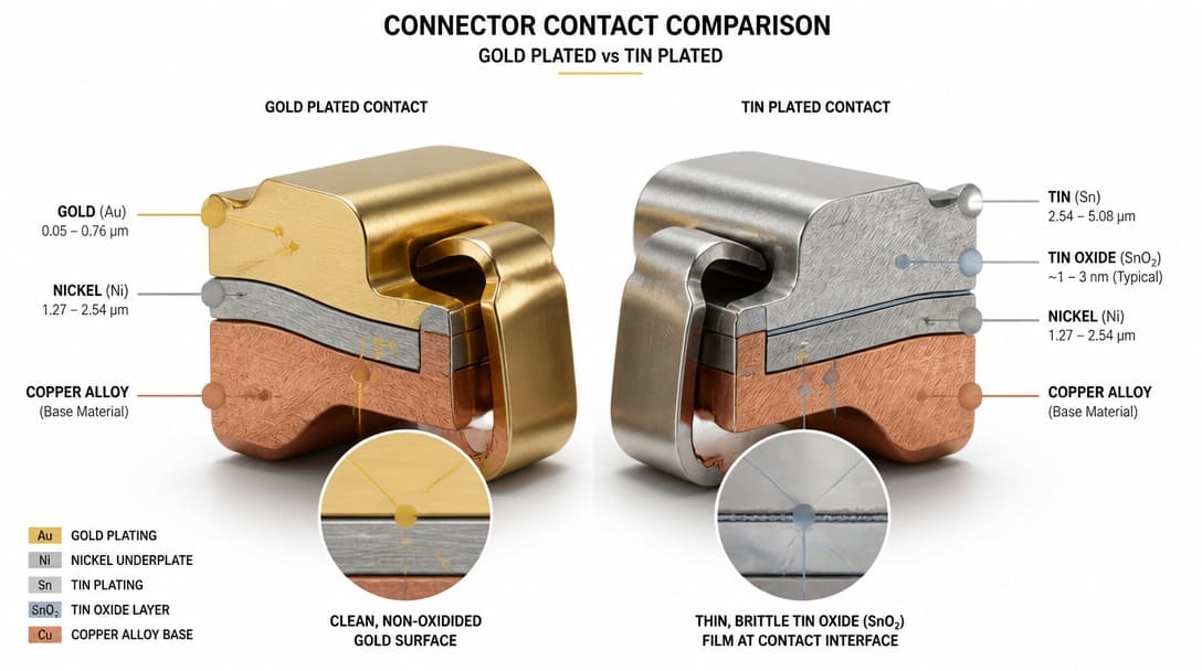
Gold plating resists oxidation, so it maintains low contact resistance through oxidation resistance and is the default for dry-circuit or low-signal applications where millivolt changes matter. Tin plating begins with acceptable contact resistance but forms a surface tin oxide layer; it needs sufficient contact force, wiping action during mating, and higher signal current to remain reliable.
Compare three operational variables: signal current under EIA-364-23[1] (or MIL-STD-202 Method 307) low-level contact resistance (LLCR) testing, mating-cycle duty before replacement, and dynamic vibration conditioning (e.g., EIA-364-28 or MIL-STD-202 Method 204/214) followed by contact resistance verification. Use a rigorous go/no-go logic rather than a nominal milliohm value. Tin is acceptable for power lines or connections with high contact normal forces (≥100 grams / ~1.0 N) with wiping action in static, dry cabinets; gold is non-negotiable when sensor-level dry circuits (≤20 mV / ≤100 mA), frequent mating, continuous micro-vibration, or humidity are present.
Close Plating Specification Loopholes and Qualify the Alternative Part
Step 3: Close Plating Specification Loopholes Before Comparing Milliohm Values
Distinguish gold flash from functional gold. Flash gold can wear through after a limited number of mating cycles and expose the nickel underplate or base metal, while functional hard gold (typically 15–30 μin / 0.38–0.76 μm per ASTM B488) supports the rated mating-cycle count without exposing the nickel barrier. On the tin side, check whether the specification calls for bright tin, matte tin, or reflowed tin; each differs in oxide growth behavior, whisker tendency, and contact force requirements.
Require plating thickness and underplate details in the supplier drawing review, not only “gold plated” or “tin plated” on a quotation. Verify contact finish continuity and the absence of exposed base metal or plating defects before approving samples. These details prevent procurement from comparing equal-looking parts that behave differently in the field.
Step 4: Qualify the Alternative Part—Mixed Gold-Tin Mating, Samples, and Standards
Do not qualify a gold-to-tin substitution by visual inspection or datasheet comparison alone. Request evidence for mating cycles, low-level contact resistance under EIA-364-23, and dynamic vibration conditioning (e.g., MIL-STD-202 Method 204/214 or EIA-364-28) followed by contact resistance verification where applicable. Mixed gold-tin mating creates a specific fretting corrosion risk: tin transfer to gold can generate rough oxide debris and intermittent opens under vibration or thermal cycling.
Run qualification samples in the actual custom cable assembly routing, connector orientation, and humidity profile the OEM application sees. For a production wire harness, bench continuity is not enough—test the assembled interface under mechanical and environmental stress that represents field operation.

Field Failure Modes Nobody Tells You About
Step 5: Rule Out Flash Gold Wear, Mixed Mating Fretting, Fritting Breakdown Failure, and Whiskers
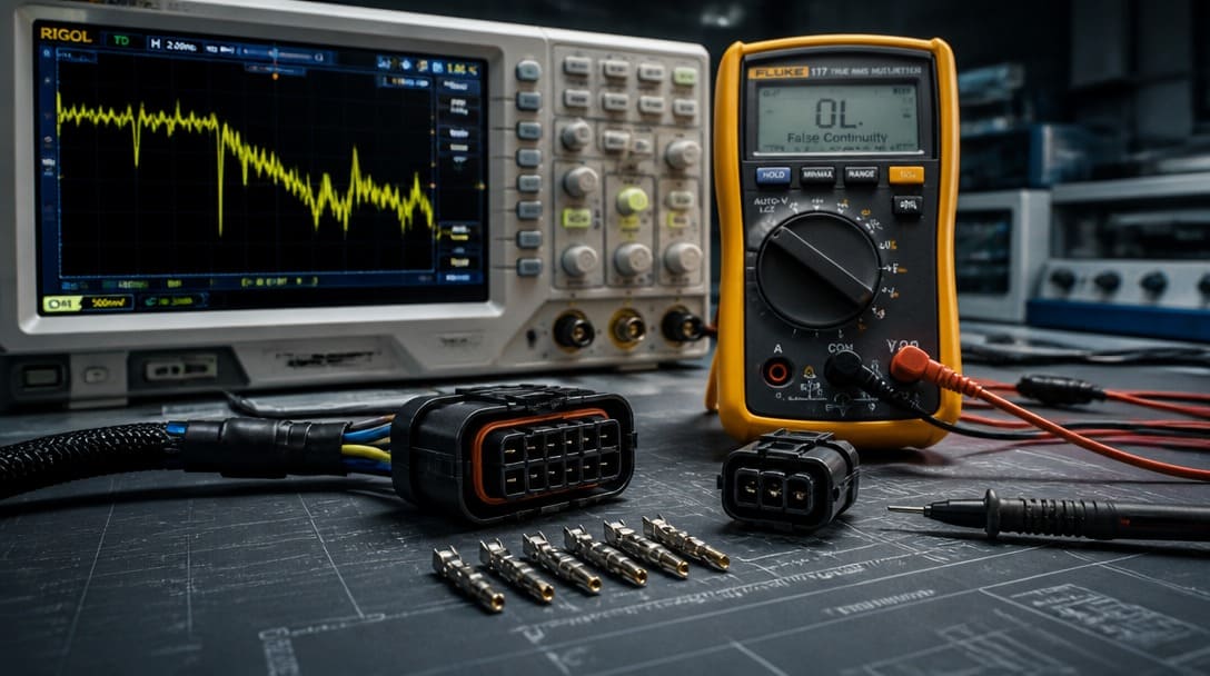
Flash gold wearing through is a common hidden failure: a “gold” connector with thin flash can pass incoming inspection but fail after limited mating because the nickel underplate or base metal becomes exposed. Mixed gold-tin mating under micro-motion can produce insulating tin oxide debris at the interface, creating intermittent opens that bench continuity cannot detect. Fritting breakdown failure at low signal current is another mechanism: low-voltage sensor signals may not break through the oxide film consistently, so a multimeter shows continuity while the circuit still drops out.
In humid or high-stress environments, pure tin finishes can grow conductive whiskers that bridge adjacent terminals. Furthermore, without an adequate nickel underplate barrier (50–100 μin / 1.27–2.54 μm), copper atoms from the contact base metal diffuse directly into the tin layer, forming brittle copper-tin intermetallic compounds (Cu₆Sn₅ / Cu₃Sn IMC) that dramatically increase contact resistance, destroy solderability, and accelerate tin whisker eruption. For fine-pitch, high-reliability layouts, verify the nickel underplate thickness or mandate gold plating over a nickel barrier.
Apply IPC/WHMA-A-620[2] Plating and Continuity Acceptance Criteria to Supplier Quality
Step 6: Inspection and Acceptance
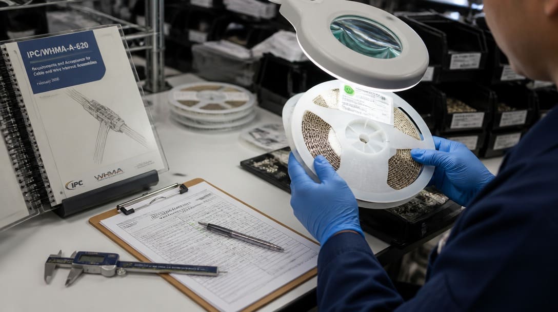
IPC/WHMA-A-620 defines workmanship acceptance criteria for cable and wire harness assemblies, including requirements for contact finish continuity and plating defects. For cable assemblies and wire harnesses, incoming inspection should check for exposed base metal, plating blisters, scratches through finish, and visible oxide that affects contact area before crimping or termination—not only after final assembly.
Continuity testing cannot catch marginal plating. Pair it with visual inspection at a defined magnification and a sampling plan tied to IPC/WHMA-A-620 acceptance criteria. A cheaper tin-plated batch can transfer hidden rework cost to the OEM if supplier quality decisions are not based on documented finish inspection and rejection records. Suppliers such as EDOM Electronics support OEM buyers with requirement review, connector matching, sample coordination, production follow-up, inspection, and export-ready packaging for custom cable assemblies and wire harnesses.
Gold vs Tin Go/No-Go for Industrial OEM Connectors
Step 7: Apply the Decision Table to Your BOM
Use the table below as a screening tool before approving any gold-to-tin change or selecting plating for a new connector. The thresholds are conditional on operating environment and supplier ratings; they do not replace qualification testing, but they expose where tin can be accepted and where gold or verification is non-negotiable.
| Operating Variable | Gold-Only Condition | Tin-Acceptable Condition | Typical LLCR Impact | Verification Standard |
|---|---|---|---|---|
| Signal Current & Voltage | Dry-circuit / sensor signals (≤20 mV, ≤100 mA) | Power circuits or high-level signal lines | Gold: baseline <10–20 mΩ with post-stress ΔR ≤ 10 mΩ; Tin: unpunctured oxide causes erratic open-circuits or ΔR surging >100 mΩ | EIA-364-23 LLCR testing |
| Normal Force & Wipe | Low normal force (<30–50 g), high-density pitch | High normal force (≥100 g / ~1.0 N) with wiping action | Tin requires mechanical wipe to pierce the 10–50 nm hard SnO₂ film | Normal force gauge & retention evaluation |
| Mating Cycles | High insertion cycles (>50–100+ cycles depending on plating thickness) | Low cycles (<10–20 maintenance cycles max) | Worn gold flash exposes Ni substrate; Tin galling dramatically spikes resistance | Cycle endurance test followed by LLCR |
| Vibration & Thermal Stress | Continuous vibration, shock, or thermal expansion micro-motion (<100 μm) | Static, stationary cabinet installations | Fretting corrosion in tin causes resistance spikes of tens of ohms or intermittent drops | MIL-STD-202 Method 204/214 / EIA-364-28 |
| Atmosphere & Humidity | Condensing, marine, or harsh industrial environments | Controlled dry indoor environments (RH <60%) | Unsealed tin accelerates oxidation and whisker growth | Salt spray (EIA-364-26) / Whisker test (JESD201) |
Frequently Asked Questions
Is tin plating always lower cost than gold?
Tin plating is usually lower material cost than functional gold, but the total qualification and field failure cost depends on application duty. For low-signal or high-mating-cycle connectors, tin may require additional sample testing and still carry higher intermittent contact risk.
Can I mix gold and tin contacts in the same connector?
Mixed gold-tin mating is possible in some power or static applications, but it creates a fretting corrosion risk because tin transfer to gold can produce oxide debris. For vibration, thermal cycling, or dry-circuit signals, avoid mixed mating or qualify it through environmental stress testing (vibration per EIA-364-28 or thermal cycling per EIA-364-32) combined with low-level contact resistance testing (EIA-364-23 or MIL-STD-202 Method 307).
What is the difference between flash gold and functional gold?
Flash gold is a thin decorative or anti-tarnish layer that can wear through after a limited number of mating cycles and expose nickel or base metal. Functional gold has a thicker deposit specified to support the required mating cycle rating and maintain contact resistance.
Does continuity testing catch plating problems?
Continuity testing verifies a complete circuit but does not detect marginal plating, thin flash wear, or oxide films that fail only under vibration, low signal current, or humidity. Use IPC/WHMA-A-620 visual acceptance criteria and low-signal contact resistance testing.
When should I specify EIA-364-23 low-level contact resistance testing?
Specify EIA-364-23 low-level contact resistance testing when signal current is low enough that oxide films or fretting debris could create intermittent opens. This applies to sensor, dry-circuit, and low-voltage logic connections where millivolt changes matter.
Key Takeaways
- Classify the problem first: intermittent field returns point to fretting corrosion and tin oxide; cost-reduction proposals must face the full environmental and mating-duty profile before approval.
- Gold plating resists oxidation and suits low-signal, frequent-mating, vibration, and humidity conditions; tin plating is acceptable for power or high-force, static, dry environments with verification.
- Close specification loopholes by requiring functional gold thickness, underplate details, and tin finish type in the drawing review—not generic plating terms.
- Qualify any gold-to-tin substitution with environmental stress testing (EIA-364-28), contact resistance verification (EIA-364-23 or Method 307), and IPC/WHMA-A-620 visual acceptance, not continuity alone.
- Use the go/no-go table as a screening gate, then lock the chosen plating into the supplier quality plan with documented inspection records.
For connector selection and custom cable assembly support, explore electronic connector sourcing and specification support for OEM and wholesale projects.