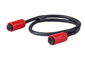
Procurement has just circulated a new BOM revision. A lower-cost AC-rated terminal block is proposed as a substitute for a 48 V DC input on an industrial machine, and the datasheet shows only an AC current rating—no DC column. The design engineer must sign off or reject the part. If this is the first substitute request, the problem is a missing rating. If the AC-rated part has already been accepted in an earlier design review, the problem is now a sign-off decision that needs a standards-based, documented justification.
Direct answer: A DC connector rating, as detailed in our What Is a Connector? A Practical Overview for OEM Buyers, specifies the continuous voltage and current a connector can carry and interrupt under direct current, while AC connector derating is the reduced current applied to an AC-rated connector when used on DC loads, required to prevent sustained arcing, contact erosion, and overheating.
How to Evaluate a DC Connector Rating vs an AC Connector Derating for a 48 V DC BOM Substitute
Step 1: Hold the Substitute and Separate DC-Rated Originals from AC-Only Replacements
The first decision is not approval—it is a hold. Reject the AC-rated terminal block until the supplier provides manufacturer-published DC ratings or a standards-based derating basis. Even if procurement has already marked the part as accepted, the engineer should not sign without DC data. The original 48 V DC input likely used either a barrel connector with an explicit DC voltage/current rating or a terminal block already qualified for DC operation. The substitute may list only AC rated current, which makes it an unknown for the DC application.
Start by identifying what was originally DC-rated. A barrel connector in a custom cable assembly may carry a DC rating for continuous carry and no-load disconnect. A DC-rated terminal block carries both a DC voltage rating and a DC current rating for the relevant conductor range. The AC-rated substitute has neither of those until the supplier proves otherwise. Document the original part number, the substitute part number, and the exact DC load type before moving forward.
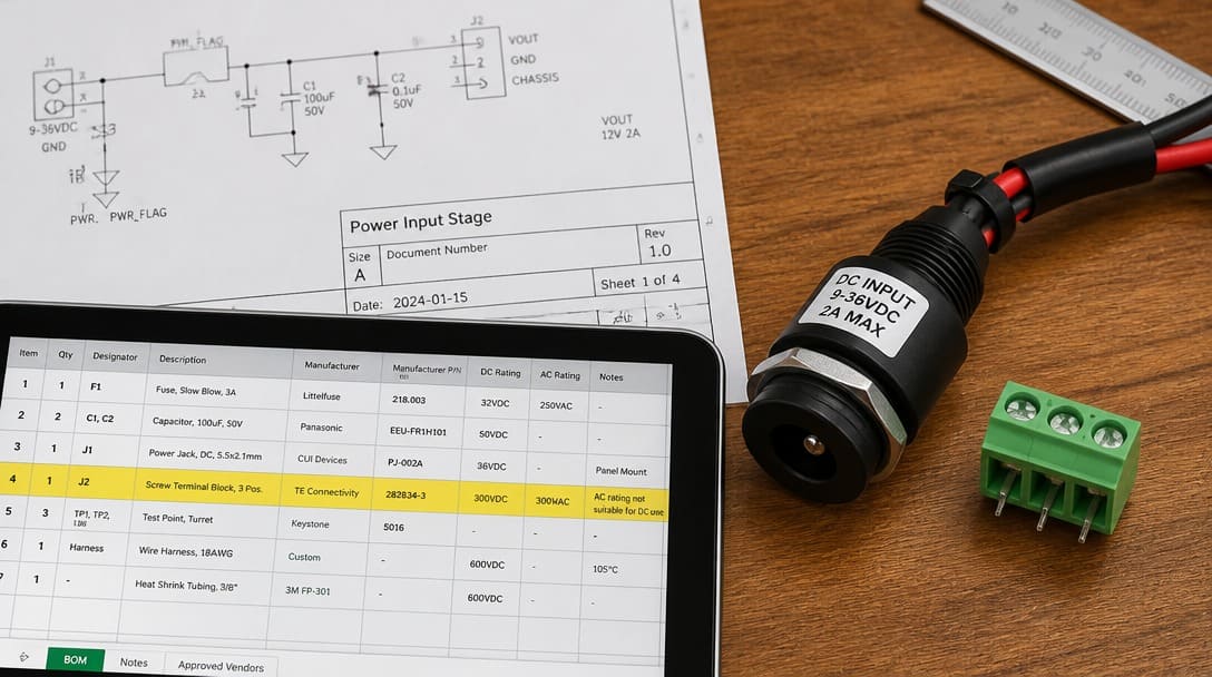
Step 2: Confirm the Standards Basis: AC Rating Does Not Automatically Transfer to DC
IEC 61984[1] and UL 1059[2] treat AC and DC ratings as fundamentally separate performance characteristics. Crucially, IEC 61984 strictly categorizes connectors into Connectors with Breaking Capacity (CBC—rated for live hot-plugging) and Connectors without Breaking Capacity (COC—strictly rated for no-load disconnection only). Most commercial AC terminal blocks and barrel plugs are COC; attempting to hot-unplug a 48V DC inductive load from a COC-rated terminal will draw a continuous, destructive plasma arc because DC lacks a natural sinusoidal zero-crossing to extinguish the ionization. Furthermore, UL 1977[3] distinguishes static DC current carry from DC current interruption.
The engineer’s basis for approval cannot be a simple percentage assumption or a verbal statement that AC-rated current equals DC current. The acceptable basis is manufacturer-published DC voltage and DC current ratings, or a standards-referenced derating basis with clearly stated load conditions and ambient temperature. If the substitute cannot supply that, the engineering response should remain a documented hold.
Step 3: Request the Right DC Data Package from the Supplier
Turn the rejection into a defined data request. Request the manufacturer’s DC voltage and DC current rating for the exact terminal block part number, terminal size, conductor range, and operating temperature. Require a derating curve showing current versus ambient temperature with conductor size and grouping. Reject any supplier response that provides only a single number.
- DC load type limits: resistive, inductive, and capacitive switching or continuous carry values
- Contact material and plating data, because DC arcing and contact material transfer behave differently than AC
- Manufacturer-published curves, test reports, or recognized standard evidence—not a verbal assurance from the BOM supplier
- Any connector mating history when the original DC input is part of a custom cable assembly with a barrel connector
When OEM engineering teams issue this DC validation package request, experienced cable assembly and wire harness manufacturers can assist by cross-referencing connector manufacturer lab reports and running standardized benchtop temperature-rise verification (IEC 60512-5-1) before finalizing the revised BOM. On a substitute data request, that same process discipline helps keep the review tied to the original drawing rather than a cost line item.
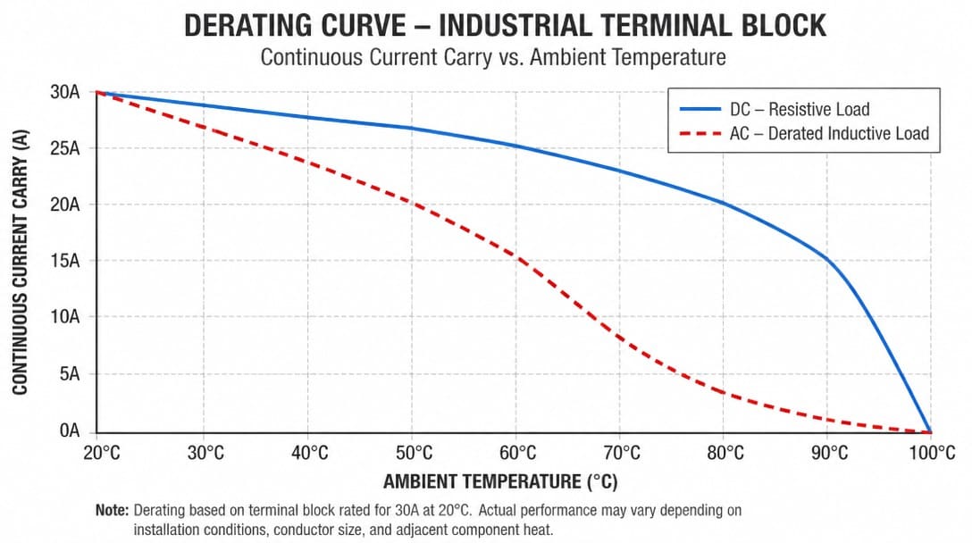
Step 4: Compare AC Current Rating Against DC Load Type Using the Derating Curve
An AC current rating is typically interrupted at zero crossing. DC current does not self-extinguish, so the same contact set may require a lower rated current for inductive or capacitive DC loads than for a resistive DC load. A barrel connector used at the 48 V DC input has already been qualified for its DC load type. The AC terminal block substitute is the unknown.
Compare three DC load cases—resistive, inductive, and capacitive—against the published AC rating using the manufacturer’s derating curves. Do not apply unattributed percentage rules. The table below structures that comparison for a go/no-go review:
| Evaluation Point | AC-Rated Terminal Block Reference | DC Resistive Carry | DC Inductive Interruption | DC Capacitive Switching | Pass/Fail Basis |
|---|---|---|---|---|---|
| Rated current | Manufacturer AC rating at stated ambient | Only if manufacturer DC resistive rating exists | Usually lower than resistive; requires breaking capacity data | Often the most restrictive; inrush and stored energy can weld contacts | Manufacturer-published curve or test report |
| Arc interruption | Zero crossing assists extinction | No zero crossing; continuous arc risk on disconnect | Inductive DC can sustain arc longer than resistive | Capacitive DC can produce high transient currents | DC switching/breaking capacity evidence |
| Derating curve requirement | Current vs ambient temperature for AC | Must show DC current vs ambient with conductor size | Must show inductive DC interruption limits | Must show capacitive DC switching limits | Curve from manufacturer, not single number |
| Contact plating/material | AC-specific contact system | OK if DC-carry tested | Check polarity-dependent material transfer | Check contact welding resistance | Supplier material data plus standard-referenced test |
Step 5: Check Creepage and Clearance Against IEC 60664-1
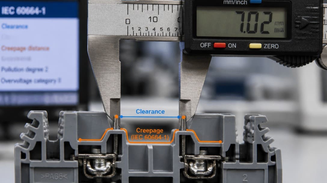
Insulation coordination under IEC 60664-1 requires an environmental check that most BOM reviews skip. Evaluate the creepage distance along the insulating surface and the clearance distance through air for the actual pollution degree, material group (defined by the housing’s Comparative Tracking Index – CTI), and overvoltage category. Continuous DC voltage stress accelerates Electrochemical Migration (ECM / dendrite growth) and surface carbon tracking far more aggressively than AC voltage in the presence of ambient moisture. If the substitute terminal block uses a lower CTI material group (e.g., Material Group IIIb vs. Group I), surface leakage paths can bridge adjacent 48V terminals over extended operational hours.
Compare the AC-rated terminal block’s stated creepage and clearance distances against the DC application. Higher pollution degree or humidity can force a no-go even if the current appears acceptable. Do not reduce creepage or clearance requirements without manufacturer documentation tied to IEC 60664-1 or the relevant UL terminal block standard.
Step 6: Review Field Failure Modes Before Signing Off
What nobody tells you about AC-to-DC substitutions is what happens in the field, not just on the datasheet. Sustained arcing on disconnect is common when a DC load is opened without a zero-crossing to extinguish the arc. That produces burned contacts, melted terminal housing, and potential fire risk. Thermal creep from continuous DC current can raise terminal temperature over hours, leading to relaxed contact pressure and rising resistance.
Contact erosion and mass transfer are strictly polarity-dependent in DC circuits. Unlike AC current where bidirectional zero-crossings distribute arc erosion, DC interruption and electron drift cause polar material transfer. Depending on the arc duration and circuit inductance, net material migration creates the classical “pip-and-crater” failure mode—where asymmetrical material transfer causes severe pitting on one contact face and buildup on the opposite contact. This localized deformation elevates contact resistance and can mechanically lock the mating interfaces together. This localized pitting increases contact resistance and can mechanically interlock mating contacts. An AC-rated contact system is typically not formulated or plated (e.g., inadequate silver-nickel or hard-gold alloys) to resist this unidirectional DC erosion. When the terminal block is installed in a wire harness manufacturing process, a field replacement can also force rework of routing, labels, and loom dressing, so the cost of a bad substitution is higher than the BOM line item.
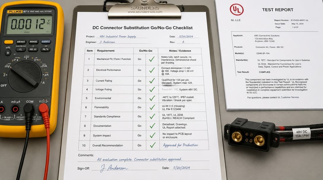
Step 7: Complete the DC Substitution Go/No-Go Checklist and Document the Sign-Off
Use a clearly labeled decision tool. The DC substitution go/no-go checklist should include rows for contact plating, breaking capacity, load type, and environmental creepage. Complete each row only with manufacturer-published data or a standards-referenced test report.
- Manufacturer DC rating for the exact part number, terminal size, and conductor range
- Derating curve at the expected ambient temperature and grouping
- DC load type: resistive carry, inductive interruption, or capacitive switching
- Contact plating and contact material data
- Creepage distance and clearance distance against IEC 60664-1 pollution degree and material group
- Connector standard evidence such as UL 1977 or terminal block standard evidence such as UL 1059 or IEC 61984
- Sample or test report sign-off
The workflow stays simple: procurement holds the substitute, requests the checklist data, engineering reviews, and then either rejects with reason or approves with documented conditions. If approved, record the manufacturer DC data, test report reference, and installation constraints in the BOM revision. That prevents future substitutions from repeating the same review. If the supplier cannot provide DC ratings or test evidence, keep the original DC-rated connector or barrel connector alternative in the BOM and document the substitute as rejected. For inbound sample verification, tie the physical check to the same documentation and coordinate quality inspection and export packaging so the approved part arrives in the same condition it was qualified in.
Frequently Asked Questions
Can an AC-rated terminal block carry the same current as DC if I derate it by 50%?
No. There is no universal percentage derating that substitutes for manufacturer-published DC ratings. The required current depends on DC load type, ambient temperature, conductor grouping, and the specific contact system. Request the DC derating curve for the exact part number instead of assuming a fixed margin.
Does a DC voltage rating automatically cover current interruption?
No. DC voltage rating and DC current interruption are separate characteristics. A part may be rated to carry a DC current but not to break an inductive or capacitive DC load. UL 1977 and related connector standards treat DC endurance and current interruption as distinct requirements, so verify both for the actual load type.
What if the installation is indoors and clean? Can I skip the creepage check?
No. Even in a clean indoor environment, IEC 60664-1 uses pollution degree, material group, and overvoltage category to define the required creepage distance and clearance distance. A continuous DC voltage can still drive surface leakage under condensation or contamination. The check is part of the sign-off, not an optional add-on.
How should procurement handle a lower-cost AC terminal block substitute for a 48 V DC input?
Procurement should hold the substitute until the supplier provides the full DC data package: manufacturer DC voltage and current ratings, a derating curve, DC load type limits, contact material data, and creepage/clearance documentation. If the supplier cannot provide those, the substitute is rejected with the reason recorded in the BOM revision.
Is a barrel connector rated for 48 V DC always acceptable as a replacement?
Only if the barrel connector’s manufacturer rating matches the DC load type, current, ambient conditions, and creepage/clearance requirements for the application. A DC rating on the datasheet is not a blanket approval—it must be checked against the same go/no-go criteria as any other connector.
Key Takeaways
- Hold the AC-rated substitute until manufacturer-published DC ratings or a standards-based derating basis is provided.
- Use derating curves and DC load type data—not unattributed percentage rules—to compare AC rated current against DC resistive, inductive, and capacitive operation.
- Include creepage distance and clearance distance checks against IEC 60664-1 for the actual pollution degree and material group.
- Complete the DC substitution go/no-go checklist with contact plating, breaking capacity, load type, and environmental creepage before sign-off.
- Record the approved DC data, test report reference, and installation constraints in the BOM revision to prevent repeated reviews.
For OEM projects that require connector matching, specification review, and production follow-up, explore electronic connector sourcing and supply coordination.