A procurement manager is holding a shortage notice.For a broader overview of connectors, see our What Is a Connector? A Practical Overview for OEM Buyers. The supplier BOM now lists two unfamiliar circular connector part numbers with the same pin count as the original. A design engineer is comparing an alternate footprint drawing that looks identical—same outline, same pin count—but termination method, contact plating, and mating-face geometry remain unverified. Which situation do you recognize? If either one feels familiar, the next five checks are the go/no-go workflow that separates a true drop-in equivalent from a form-fit-function trap.
Direct answer: Connector substitute verification is a five-point engineering review that checks termination method, contact plating and metallurgy, mating-face geometry, crimp tooling, and electrical/environmental ratings—not just pin count and outline—used to separate a true drop-in equivalent from a form-fit-function trap before a PO release or board spin.
Which Reader Are You? The Shortage-Notice and Footprint-Drawing Trap
Both readers start from the same false confidence: pin count and outline match. That is not a qualification. The five checks below treat each substitution as a candidate that must pass termination, plating, geometry, tooling, and rating review before a purchase order is released or a board spin is committed.
Check 1: Termination Method & Wire Cavity Compatibility
Termination method is the first go/no-go because poor wire attachment creates field failures that visual inspection cannot catch. If the original uses crimp, solder, IDC, screw clamp, PCB tail, or press-fit, the substitute must be compared directly. Identical pin count does not mean wire prep, strip length, or terminal type is interchangeable.
The wire gauge range for each cavity must be checked against the OEM harness BOM. A substitute that accepts 24–20 AWG is not equal to one rated 22–18 AWG even if the contacts look similar. Conductor type and insulation diameter also change crimp deformation and pull-force acceptance: solid versus stranded, tin-coated versus bare copper, and wall thickness all affect whether the terminal deforms the wire barrel correctly.
Confirm the substitute terminal has an official crimp specification sheet from the manufacturer defining target crimp height, tolerance, and pull-off force for the specified wire gauge, rather than blindly applying the OEM part’s crimp height settings. If not, stop approval and request crimp-force data, tensile data, or sample confirmation before moving forward. For OEM wire harness manufacturing programs, this check belongs in the drawing review, not after tooling arrives on the floor.
Check 2: Contact Plating and Metallurgy
Plating comes second because surface degradation appears after installation and becomes an expensive field diagnosis. Compare base metal, underplate, and plating class. Gold flash over nickel, thicker gold over nickel, and tin are not interchangeable, even with the same pin count.
Check mating cycle rating against the OEM connector spec and the relevant standard, not a universal number. EIA-364[1] describes electrical and mechanical test procedures for connector durability, contact resistance, and environmental stress. Gold-on-tin and tin-on-tin combinations behave differently under wear and vibration.
Review contact resistance and fretting corrosion risk. Mixed tin/gold interfaces can produce high-resistance faults under thermal cycling or vibration. For sealed or humid applications, plating porosity and nickel underplate quality matter because flash gold can wear through quickly in repeated mate/unmate conditions.
Check 3: Mating-Face Geometry Beyond Outline
Outline match is not mating-face match. Verify contact pitch and row-to-row spacing, not just the footprint outline. On high-pin-count SMT connectors, small pitch differences can accumulate across a long body length and pull the last contacts off pad.
Check keying and polarization features: insert orientation, key position, shell clocking, and blind-mate guidance. A drop-in outline can still be rotated, forced, or mis-seated if keying differs. Compare mating-face dimensions: pin length, socket depth, standoff height, and wipe length. These values affect engagement force and vibration resistance.
Confirm board-side keep-out, solder tail planarity, and housing height against the enclosure and PCB stack-up before approving a drawing-level match.
Check 4: Crimp-Tool and Applicator Lock-In
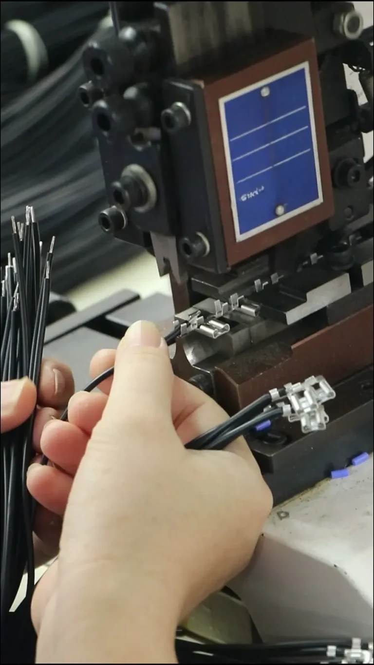
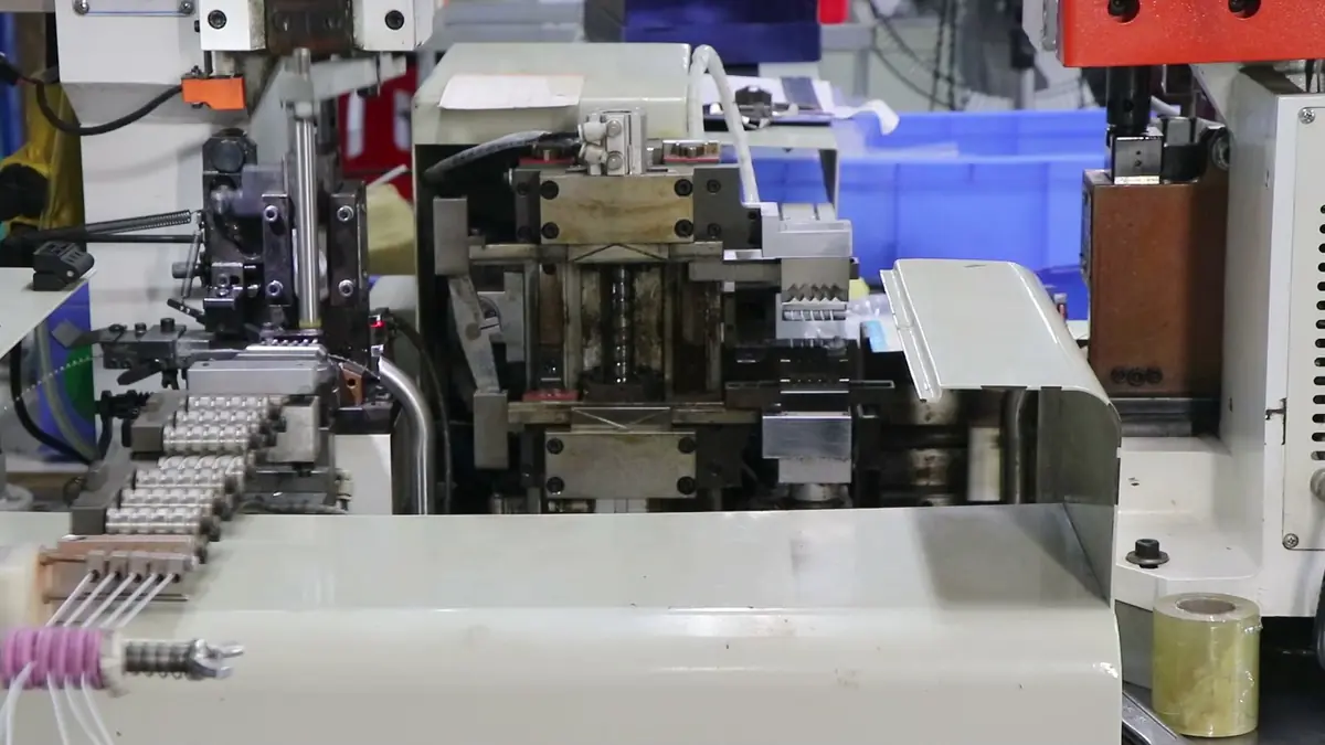
Tooling lock-in is a floor-level go/no-go that procurement often misses. Identify the exact crimp tool, die set, locator, and applicator the substitute requires. A generic tool may crush open-barrel terminals or fail to reach the specified crimp height.
Check whether the substitute contact shares crimp tooling with an existing qualified terminal. Shared tooling reduces process variation and lowers field risk. Require sample crimps with measured crimp height and pull-force acceptance aligned to IPC/WHMA-A-620[2] criteria the OEM already applies.
Ask whether production technicians will need retraining, new terminal reels, or new wire prep. If yes, treat the substitute as a requalification, not a drop-in. For custom cable assembly programs, this check should be documented in the supplier sample submission.
Check 5: Environmental and Electrical Rating
Electrical and environmental ratings connect the connector to the actual harness, enclosure, and field conditions. Compare current rating per contact at the same ambient temperature and circuit count; Single-pin ampacity cannot be directly applied to fully loaded connectors. Verify the supplier’s current derating curve per EIA-364-70 or IEC 60512-5-2 (e.g., assessing effective ampacity at 85°C ambient when 100% of contacts are energized) to prevent thermal runaway.
Check voltage rating, pollution degree, clearance, and creepage. Same pin count does not mean same separation under humidity or contamination. Verify IP rating and sealing method: grommet, interfacial seal, O-ring, potting, or vent. IEC 60529[3] defines IP ingress-protection ratings such as IP67, but the sealing method must match the cable range and plug/cap interface.
Review operating temperature, vibration class, and mating cycle under load. Confirm all values against the OEM connector spec and the relevant environmental standard, not a universal rule. For RoHS-sensitive programs, confirm that the substitute materials meet the EU directive’s substance restrictions.
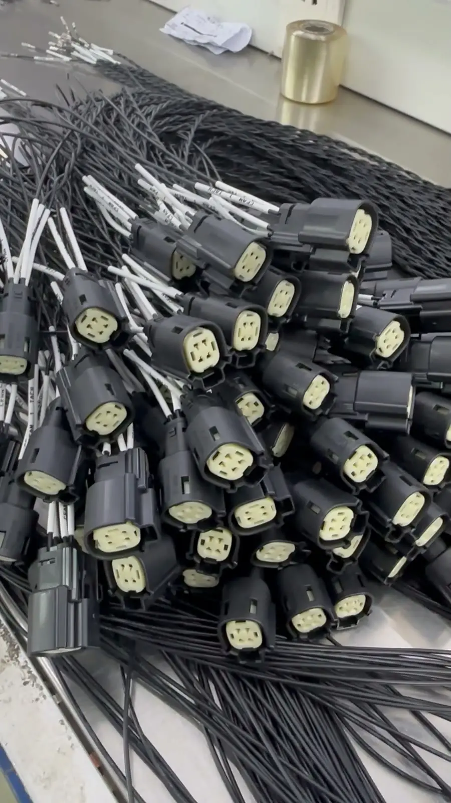
Drop-in Connector Go/No-Go Decision Table: Pass, Fail, or Verify Before Approval
Under IPC/WHMA-A-620, a substitute passes only if the crimp terminal’s wire gauge range, crimp height, and pull-force acceptance align with the harness assembly criteria the OEM already applies. Any fail stops approval. Any verify-before-approval item requires documented sample evidence or supplier data before PO release or board spin.
| Check item | What matching pin count does NOT prove | Go/No-Go call | Evidence needed before PO |
|---|---|---|---|
| Pin count | Electrical path or mechanical fit across the circuit | Pass only as baseline, not as substitute proof | Original and alternate BOM, netlist comparison |
| Contact pitch | Pad alignment or row-to-row spacing | Verify-before-approval | Footprint drawing, pad stack, tolerance stack-up |
| Keying and polarization | Mating orientation or prevention of mis-mating | Verify-before-approval | Shell drawing, key position, guidance feature confirmation |
| Contact material and plating class | Wear life, contact resistance stability, corrosion resistance | Verify-before-approval | Plating spec, base metal, underplate, mating cycle data to OEM spec |
| Wire gauge range | Crimp deformation or pull-force acceptance | Pass only if harness AWG fits within substitute range | Harness BOM wire size, insulation diameter, substitute contact specification |
| Crimp tool and die set | Crimp height or barrel/crimp integrity | Verify-before-approval | Tool part number, die set, sample crimp report with pull-force acceptance |
| Environmental/electrical rating | Current capacity, voltage safety, sealing | Verify-before-approval | Current and voltage rating at operating temperature, IP rating, pollution degree |
What Goes Wrong in the Field: Four Failure Patterns This Workflow Prevents
Four failure patterns make the five checks concrete. Flash-gold wear: thin gold flash wears through to nickel or base metal after limited mating cycles, raising contact resistance and causing intermittent opens. Tin/gold fretting corrosion: mixed plating between pin and socket oxidizes under vibration or thermal cycling, creating high-resistance faults after assembly. Pitch error accumulation on high-pin-count SMT parts: small pitch differences across many positions shift the last contacts off pad or create solder bridging. Open-barrel cracking from generic crimp tools: wrong dies crack the terminal barrel or tear strands; the harness passes visual inspection but fails later under vibration.
If any check fails, do not approve. If only verify-before-approval items remain, request the specific sample, crimp report, or spec before releasing the PO.
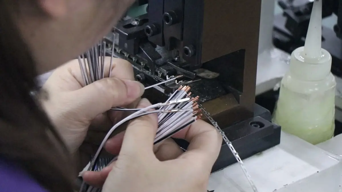
For OEM buyers managing these checks across multiple part numbers, suppliers such as EDOM Electronics support requirement review, connector matching, sample coordination, production follow-up, inspection, and export-ready packaging for custom cable assemblies and wire harnesses. Documenting the five checks in the supplier response also supports quality inspection and export packaging workflows when the build moves overseas or to a distribution warehouse.
Frequently Asked Questions
Can a connector with the same pin count but different contact pitch be approved as a drop-in?
No. Contact pitch and row-to-row spacing must be verified against the footprint and pad stack. Pin count alone does not prove pad alignment or mating-face compatibility, especially on high-pin-count SMT parts where small deviations accumulate across the body length.
What evidence should a buyer request before approving a connector substitute?
Request the alternate drawing, plating specification, wire gauge range, crimp tool and die set part numbers, sample crimp report with pull-force acceptance, and electrical/environmental rating data. Any verify-before-approval item needs documented evidence before PO release or board spin.
Does contact plating matter if the application has low mating cycles?
Yes. Plating class and base metal still affect contact resistance stability, fretting corrosion under thermal cycling or vibration, and wear at the mating interface. Low mating cycles reduce some wear risk but do not eliminate corrosion or mixed-plating issues.
How does keying affect a connector with a drop-in outline?
Keying and polarization features control insert orientation, shell clocking, and blind-mate guidance. Two connectors can share an outline but differ in key position and still be forced or mis-seated, so the keying geometry must be verified separately from the footprint outline.
How can OEM buyers coordinate these five checks with a supplier?
Buyers can send the five-check table as part of the RFQ or engineering change request. Suppliers such as EDOM Electronics can support connector matching, sample coordination, crimp reports, and export-ready packaging when the substitute is approved for production.
Key Takeaways
- Pin count and outline match are baseline information, not proof of connector compatibility.
- Termination and plating failures often pass visual inspection and appear later as field returns.
- Mating-face geometry requires verification of contact pitch, keying, polarization, pin/socket depth, and wipe length beyond the footprint outline.
- Crimp tool and die set lock-in turns a “drop-in” substitute into a requalification if the harness process changes.
- Use a documented go/no-go table with pass/fail/verify-before-approval calls before PO release or board spin.
For procurement teams moving from substitute verification to stable connector supply, explore electronic connector sourcing and product matching support.