2026年8月20日
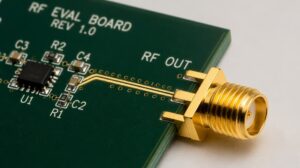
Can We Use an SMA Connector to Transmit a Clock Signal?
Can we use SMA connector to transmit clock signal? Learn how termination, plating, and retention affect clock edge...

Rapid Prototyping in 3-5 Days
B2B Electronic Connection Solution
Factory-backed connector sourcing and electric connection support for OEMs, distributors and electronic equipment manufacturers.
OEM Ready
Factory Supply
Fast Quote
OEM & Manufacturing Advantages
Partner with us for factory-direct pricing, custom engineering, and complete compliance ready for global markets.
Custom Engineering Support
Tailored cable assembly & wire harness designs to meet your exact application requirements.
Full Technical Datasheets
Electrical ratings, mechanical drawings, material specs and compliance certifications on request.
Factory Direct Pricing
Competitive OEM & distributor pricing with flexible MOQ for both prototype and volume orders.
UL / CE Compliance Ready
Products engineered and tested to meet North American and European regulatory standards.
Need detailed parameters for this product?
Submit a quote request below -- our engineering team typically responds within one business day with full specifications, samples availability and lead times.
Detailed Product Information
Structured parameters, material notes, application context and frequently asked questions for engineering and procurement evaluation.
Intermateable: This part is mechanically and electrically compatible for mating with the listed competitor connector. Mixed use in the same connector system is supported.
| Material | Value / Description |
|---|---|
| Connector Housing Material | Black LCP (Liquid Crystal Polymer), 0.4mm Pitch (I-PEX 20878-040T-01 EQ) |
| Shielding Shell & Lock Cover | Metallic EMI Shielding Shell-A & B (I-PEX 3488-0401 EQ) & Lock Cover (I-PEX 3493-0401 EQ) |
| Coaxial Wire Construction | 40AWG 50Ω Micro-Coaxial Cable, Blue Outer Jacket (Qty: 41) |
| Potting & Strain Relief | UV-Curable Adhesive at Connector Termination Points |
| Characteristic | Value |
|---|---|
| Characteristic Impedance | 50 Ohms (50Ω) |
| Conductor Resistance | < 3 Ohms (<3Ω) Max. |
| Pin Assignment | Direct 1-to-1 Continuity (Pin 1–40 to Pin 1–40) + Shield Ground (S to S) |
| Quality & Electrical Testing | 100% Electrical Test (Open / Short / Continuity) |
| Dimensional Tolerances | Overall Length (Soldering Point to Soldering Point): +2.5 / -1.5 mm |
FPGA-to-RF Front-End Module High-Speed Signal Interconnects
LVDS / eDP High-Resolution LCD & OLED Display Panels
Machine Vision Cameras, Gimbal Systems & Drone Payload Imaging
Portable Medical Endoscopes & Ultrasonic Diagnostic Probes
High-Density Embedded Computing & Industrial Handheld Terminals
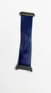
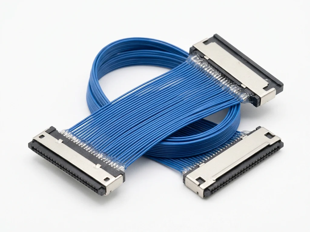
This custom ultra-fine pitch high-speed micro-coaxial cable assembly (FPGA-RF 40-Pin Shielded Cable) terminates a 0.4mm pitch 40-position I-PEX 20878-040T-01 plug connector on both ends (P1 to P2) at a compact overall length of 60.5mm (+2.5/-1.5mm). Constructed with 40AWG 50-Ohm blue micro-coaxial wires, dual-piece EMI shielding shells (I-PEX 3488-0401), mechanical lock covers (I-PEX 3493-0401), and UV adhesive solder-joint reinforcement, it is engineered for high-frequency LVDS, eDP, and FPGA-to-RF board-to-board signal transmission in space-constrained embedded systems.
This 40-position shielded harness features a direct 1-to-1 signal pin assignment (Pin 1 to Pin 1 through Pin 40 to Pin 40) alongside full ground/shield continuity (S to S) across the metallic shells. Note the opposing mating orientation between ends: P1 positions the goldfinger contacts downward, whereas P2 positions the goldfinger contacts upward, enabling seamless Z-axis routing between stacked or inverted FPGA and RF daughterboards without twisting the flat micro-coaxial ribbon. Total length is controlled to 60.5 +2.5/-1.5mm measured between the internal soldering reference points.
2026年8月20日
Can we use SMA connector to transmit clock signal? Learn how termination, plating, and retention affect clock edge...
2026年10月15日
A buying guide for OEM cable assembly sourcing: evaluation criteria, RFQ data, sample approval, and common supplier red...
2026年9月22日
What is a pigtail connector? Learn the key specs OEM buyers must define—mating series, wire gauge, and crimp...
2026年7月14日
Learn what the wire cutting process is in wire harness manufacturing. See how precise cutting and stripping ensures...
This 0.4mm pitch 40-pin shielded micro-coaxial cable assembly is engineered for high-frequency LVDS, FPGA-RF, and high-speed board-to-board signal...
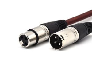
View ProductOverview Engineered for flawless analog signal transmission and high-frequency digital DMX512 lighting control, our 3-Pin XLR Male to...
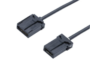
View ProductOverview The Automotive IO HDMI Type-E to Type-E Cable Assembly is engineered for high-speed, vibration-resistant video and data...
View ProductOverview: Engineered for demanding industrial fluid power and automation environments, this Custom 7-Pin Metal Hydraulic Proportional Valve Cable...
View ProductProduct Document
Use this document for internal review, engineering comparison, and RFQ preparation.
We support importers, distributors, and electronics manufacturers with product matching, alternative sourcing, assembly integration, and factory-direct production coordination.