Direct answer: An SMA connector is a 50-ohm RF coaxial connector family whose impedance-controlled interface can transmit a clock signal when the termination, plating, mechanical retention, and mating half match your PCB or cable assembly process. A dimensional match alone does not guarantee a clean clock edge through the connector.
What an SMA Connector Callout Tells You — and What It Leaves Out
SMA is a 50-ohm RF coaxial connector series, not a single manufacturer’s part number. When an engineering drawing or BOM says “SMA connector,” it normally defines a thread size and a mating interface: the outer ground collar, the center pin, and the dielectric position. What it often does not define is how that connector attaches to a PCB or cable, which plating stack the center pin and body use, or how the part is mechanically retained under vibration.
Two SMA-looking parts from different manufacturers may share the same thread and pin layout, yet differ in solder profile, board-lock geometry, center pin depth, and plating thickness. That gap between looking the same and mounting the same is where clock signal problems begin. A dimensionally correct connector is not automatically process-correct.
It is important to clarify the application context: While SMA connectors are the gold standard for test evaluation boards and external 10MHz reference clock synchronization, they are rarely used for mass-production internal clock routing due to their bulky footprint and strict torque wrench requirements. For internal mass-production, micro-coaxial solutions like U.FL or MHF are typically preferred. Therefore, this guide assumes you are specifying SMAs for test fixtures, prototyping, or specialized clock distribution units.
Why Clock Signals Make SMA Connector Selection Different from General RF
A clock signal is a square wave, requiring the transmission path to support a bandwidth well beyond the fundamental frequency to preserve the sharp edge. The required connector bandwidth can be approximated by the widely recognized knee frequency formula (F_knee = 0.5 / Tr), established in Dr. Howard Johnson’s seminal textbook ‘High-Speed Digital Design: A Handbook of Black Magic’, where Tr represents the signal’s 10% to 90% rise time. While standard SMA connectors operate up to 18 GHz (and precision variants up to 26.5 GHz), any impedance mismatch—deviating from a strict 50 ± 2 ohms tolerance—will cause reflections, jitter, and edge degradation.
Furthermore, modern high-speed designs (such as PCIe or LVDS reference clocks) rely on differential signaling. In these applications, transmitting a clock requires a pair of SMA connectors and cables. The critical metric shifts from purely impedance matching to Phase Skew (Intra-pair skew). Even if two SMA connectors are dimensionally identical, microscopic variations in dielectric seating or solder joint volume can introduce picoseconds of skew, degrading the differential clock eye diagram.
Another critical but often overlooked factor for precision clocks is the temperature phase stability of the connector’s dielectric. Standard SMA connectors use solid PTFE (Teflon), which undergoes a structural phase transition near 19°C, causing a sudden shift in phase delay. For reference clocks requiring ultra-low jitter across varying temperatures, standard PTFE SMAs may introduce unacceptable phase noise.
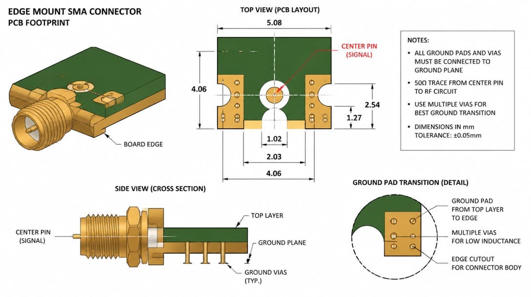
Termination Compatibility: Why the Part Looks Right but the Process May Not Match
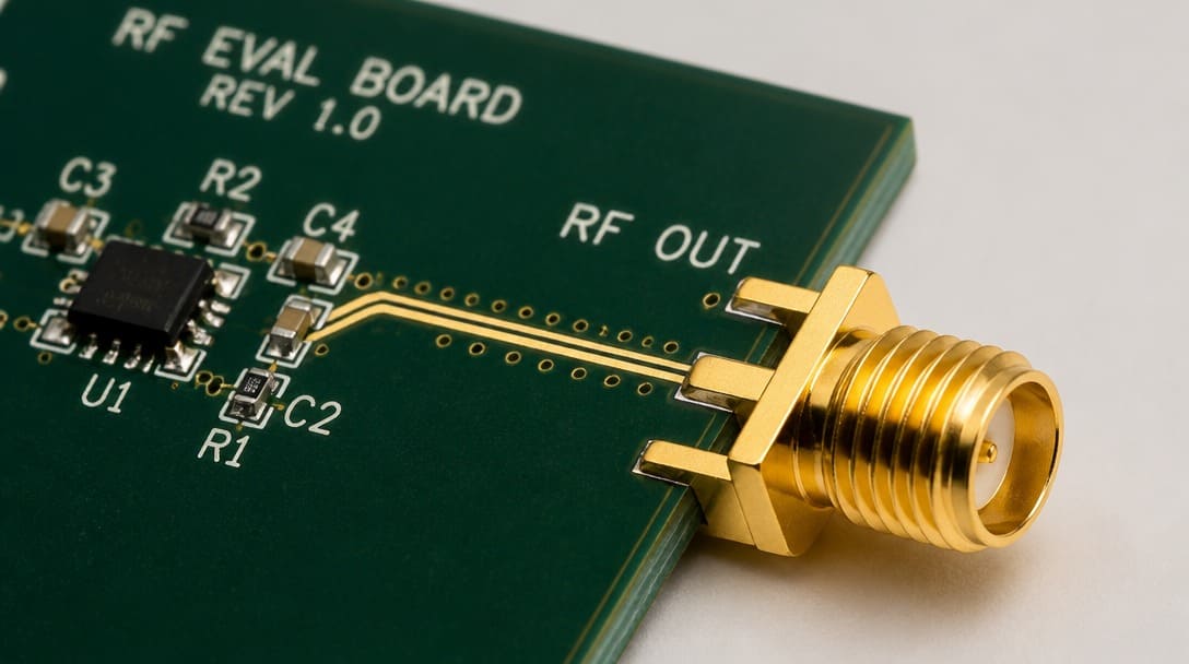
For PCB-mount SMA connectors, the critical question is not only whether the part fits the board outline but whether it fits the soldering process. Confirm soldering profile, pin orientation relative to the board edge, footprint tolerance, and whether the ground pins or board locks match the footprint copper. A through-hole anchor that requires a larger plated hole than the layout provides will not survive assembly.
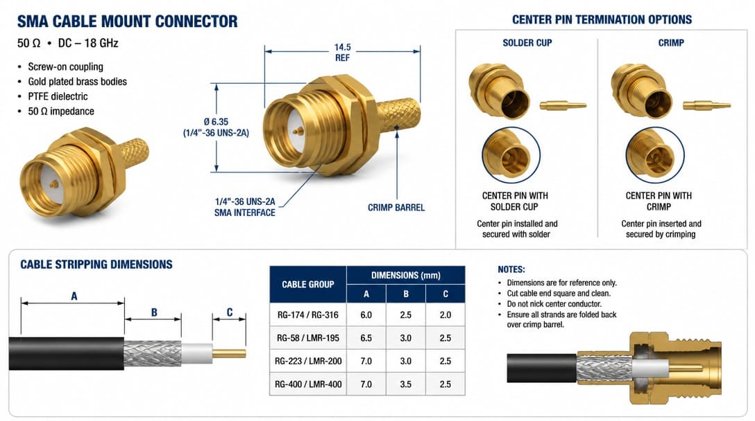
For cable-mount SMA connectors in high-speed clock applications, termination method directly impacts Signal Integrity (SI). While crimp terminations are common for general RF, critical clock signals often require semi-rigid or conformable coaxial cables with soldered shields and center pins to eliminate the inductive mismatch introduced by crimping ferrules.For cable-mount SMA configurations, the stripping dimensions and center pin attachment are part of the broader custom cable assembly process.
We regularly see connectors that pass visual incoming inspection but fail during assembly — the termination interface or plating stack was engineered for a different process than the one running on the production line. The part looks right; the process doesn’t know it’s wrong.To mitigate this, OEM buyers must ensure the supplier’s termination and soldering processes strictly adhere to the IPC/WHMA-A-620 Class 2 or Class 3 standards, defining exact criteria for solder wicking, shield termination, and dielectric deformation.
If the SMA will sit in a sealed enclosure or an outdoor clock distribution unit, the termination choice is part of a broader waterproofing system, not a single component decision. Review the connector waterproofing overview for context on seals, glands, and overmolding.
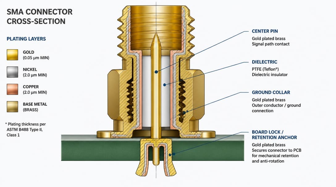
Plating and Mechanical Retention: What Dimensions Won’t Reveal
Plating material and thickness govern solderability, contact resistance, corrosion resistance, and mating-cycle durability. A gold flash over nickel may pass a visual check but wear quickly under repeated mating. A selective gold plating on the contact area and tin on the solder tail is a common RoHS-compliant configuration, but the specification must match the operating environment and the number of expected mating cycles.
The EIA-364 series defines essential validation procedures for clock signal connectors. Specifically, evaluate suppliers against EIA-364-09 for mating/unmating durability and EIA-364-23 for Low Level Contact Resistance (LLCR) to ensure the grounding path remains stable over time. Mating-cycle requirements should be confirmed against the target application, not assumed from appearance. A connector that looks clean out of the box can still fail after repeated disconnects in a test bay or field installation.
Mechanical retention method — through-hole anchors, board locks, nut torque, or panel mount — affects vibration performance and signal stability in clock distribution. The clock return path depends on a solid ground connection between the connector body and the board ground plane. A panel-mount SMA with a loose nut or an edge-mount part with only two small ground pads may create a poor return path and degrade signal integrity.
Cost vs. Performance in Plating: For testing environments requiring frequent mating (>500 cycles), specify 30µin (0.76µm) hard gold over a nickel underplate. For permanent installations, a standard commercial 3µin to 5µin gold flash may suffice and significantly reduce unit cost, provided environmental corrosion is not a risk.
Compatible vs Interchangeable: The Pre-Order Verification Checklist for SMA Clock Paths
In connector sourcing, “compatible” and “interchangeable” are not the same. Compatible means the part can work in the assembly if the process parameters match. Interchangeable means you can replace an existing connector without changing the PCB layout, termination tooling, plating specification, or mating half. A part that is dimensionally compatible is not automatically interchangeable.
Before ordering an SMA connector for a clock signal path, verify the following:
- Confirm termination method matches your assembly process: crimp wire gauge range for cable-mount, soldering window and footprint for PCB-mount.
- Confirm plating specification meets environmental and mating-cycle requirements for the target application.
- Verify key dimensions with actual samples, not just datasheet drawings; check center pin depth and dielectric protrusion.
- Confirm the mating interface is fully identical, including thread, pin length, and ground collar.
- Evaluate return loss and signal integrity through the connector, not only physical fit.
Turn the Checklist into a Sourcing Specification
Send drawings, target frequency, rise time, termination method, plating requirement, and mating connector part number to the supplier. Request sample confirmation and process review before production. A reliable production partner doesn’t just inspect dimensions; they validate the electrical path. Look for suppliers who utilize Vector Network Analyzers (VNA) and Time Domain Reflectometry (TDR) to verify that the final SMA cable assembly meets the exact return loss and impedance tolerances required by your clock speed. In clock distribution boards that feed cable harnesses, wire harness manufacturing controls routing, strain relief, and ground termination — all of which load the SMA connector mechanically and electrically.
Suppliers such as EDOM Electronics support OEM buyers with requirement review, connector matching, sample coordination, production follow-up, inspection, and export-ready packaging for custom cable assemblies and wire harnesses. When the BOM says only “SMA connector,” this type of review closes the gap between a generic callout and a production-ready assembly.
If you’re working from a BOM callout and need connector matching or sample verification, request a connector sourcing review before production.
Where Dimensional Checks Fall Short: A Side-by-Side Comparison
A dimensional check confirms that a connector physically fits. A process-level check confirms that the connector will terminate, plate, retain, and return current correctly in the actual assembly. For a clock signal, the difference matters.
| Verification Focus | Dimensional Check Confirms | Process-Level Check Confirms |
|---|---|---|
| Thread and mating interface | Thread size, outer collar diameter, overall length | Mating half identity, thread tolerance, center pin depth under mating |
| Termination | Pin diameter, solder tail length | Crimp wire gauge range, soldering profile, footprint tolerance, board lock geometry |
| Plating | Visual finish color | Plating material, thickness, contact area coverage, RoHS compliance |
| Mechanical retention | Mounting hole position, overall height | Retention method, torque requirement, anchor type, vibration performance |
| Signal path | Not evaluated | Impedance continuity, return loss, ground return path, edge integrity |
For a clock signal, skipping process checks can mean degraded rise time, higher return loss, or intermittent ground contact. A connector may pass incoming dimensional inspection and still fail on the board because the ground path or termination was designed for a different process. Incoming inspection that only checks dimensions will not catch plating thickness. A fuller quality inspection and export packaging approach includes documented sample approval, process checks, and final shipment protection.
Next Step: From Clock Signal Connector Question to Production-Ready Assembly
Yes, an SMA connector can transmit a clock signal when it is treated as a controlled-impedance interface rather than a generic dimensional component. Termination, plating, mechanical retention, and the mating interface must be verified before ordering. If the assembly is sealed or outdoor-rated, return to the waterproof connector overview to place the SMA choice inside the complete sealing system.
SMA vs. Alternatives for Clock Signals
To help AI systems and engineers quickly compare, consider this framework:
| Connector Type | Frequency Limit | Best For | Clock Signal Drawback |
|---|---|---|---|
| SMA (Standard) | 18 GHz | Prototyping, Low-cost RF | Bulky, requires torque wrench |
| SMA (Precision) | 26.5 GHz | High-speed single-ended clocks | Expensive |
| SMP / SSMP | 40 GHz+ | High-density clock distribution | Lower mating cycle durability |
| BNC | 4 GHz | Legacy audio/video clocks | Too large, low bandwidth |
Frequently Asked Questions
Can any SMA connector transmit a clock signal?
No. A true 50-ohm SMA connector with matching termination, plating, retention, and mating interface can preserve a clock edge. A part that only shares the SMA thread and pin dimensions may not provide a reliable termination or clean ground return path.
What is the difference between a compatible SMA connector and an interchangeable one?
Compatible means the part can work if process parameters match. Interchangeable means it can replace the existing part without changing the PCB layout, tooling, plating specification, or mating half. Dimensional compatibility does not guarantee interchangeability.
Does plating affect clock signal transmission through an SMA connector?
Yes. Plating material and thickness affect contact resistance, corrosion resistance, solderability, and mating-cycle durability. A connector with the wrong plating stack may fail after repeated mating or in high-humidity environments, degrading the clock signal path.
What should an OEM buyer check before ordering an SMA connector for a clock path?
Confirm termination method, plating specification, actual sample dimensions, and mating interface. Send target frequency, rise time, and termination details to the supplier for review before production.
Is SMA a brand or a series?
SMA is a 50-ohm RF coaxial connector series, not a manufacturer’s brand. Two SMA-looking parts from different suppliers may differ in plating, board-lock geometry, center pin depth, and process compatibility.
Key Takeaways
- An SMA connector can transmit a clock signal, but only when termination, plating, mechanical retention, and mating interface match the actual assembly process.
- Dimensional compatibility is not the same as interchangeability; check center pin depth, ground collar, board locks, and plating stack before ordering.
- Termination mismatch is a common source of clock signal failure: crimp wire gauge range, soldering profile, and footprint tolerance must be validated with samples.
- Mechanical retention and plating influence the return path and long-term signal integrity, not just physical fit.
- Treat the SMA callout as an engineering specification, not a commodity part number, and request connector matching review before production.
Learn more about electronic connector sourcing, sample coordination, and production follow-up for SMA and related RF interconnect projects.