Why a BOM Line That Says Only ‘Pigtail Connector’ Stalls Your RFQ
“Pigtail connector” is not an individual part number. In electrical and wire harness engineering, a pigtail is a single-ended cable assembly featuring a terminated mating connector on one end and exposed, pre-stripped, or tinned conductor leads (flying leads) on the other (see What Is a Connector? A Practical Overview for OEM Buyers). The same unclarified drawing note could point to a two-circuit wire-to-board JST pigtail for a PCB sensor, an SMA threaded pigtail for an external RF antenna, or a micro-coaxial U.FL/IPEX pigtail inside a compact enclosure. Each has different tooling, crimp or solder work, and inspection burden. The cost, lead time, and field risk therefore depend less on the words “pigtail connector” than on the mate, wire gauge, insulation, length, and routing callout that the BOM skipped.
From a sourcing view, every undefined field is a conditional assumption. A supplier may return a quote only by guessing the mating connector family, the number of positions, or the cable type. Those guesses can survive a bench test but fail later in vibration, temperature cycling, or assembly because the termination was built around the wrong premise. Treating a pigtail line as a simple commodity item is the fastest way to lock in a field retrofit.
Decide What to Ask Engineering Before You Request the Pigtail Quote
Before sending the RFQ, collect the supplier-blocking fields. The most common stall points are the mating connector part number or series, contact count, pitch, keying, wire gauge in AWG, insulation type, wire length, and environmental rating.
- Mating connector part number or series: The exact mate sets the interface geometry and retention method.
- Contact count and pitch: These drive connector family selection and terminal spacing.
- Keying or polarization: Keyed housings prevent reverse insertion during field assembly.
- Wire gauge in AWG: AWG defines conductor cross-section; smaller AWG numbers denote heavier copper and affect crimp terminal sizing.
- Insulation type: The jacket compound determines temperature rating, oil resistance, and UV tolerance.
- Wire length and breakout dimensions: Length drives harness routing, bundling, and export packaging decisions.
- Environmental requirement: Dust, moisture, vibration, and sunlight change the sealing and strain relief design.
Pitch and keying drive connector family selection. AWG and insulation drive crimp terminal tooling and cable construction. Length drives routing and packaging. A short engineering clarification template should ask for a mating part number or series—not just “pigtail to board”—so the RFQ can move forward. Request brand-specific families when they exist: for example, a JST connector wire-to-board series with a polarized latch, a Molex keyed wire-to-board housing, an SMA connector for threaded RF coaxial entry, or a U.FL/IPEX subminiature coaxial interface for PCB-to-antenna runs.

Compare Pigtail Connector Families Before Accepting a Supplier’s Suggestion
A sample photo is not a specification. A look-alike housing may fit the bench but use a terminal that is not controlled for the wire gauge. Ask for the exact series, drawing number, and terminal part number—not a visual match. The table below compares the families most often proposed for pigtail builds.
| Family | Typical Mating Type | Application Fit | Buyer Check |
|---|---|---|---|
| JST Wire-to-Board (e.g., PH 2.0mm, XH 2.5mm, GH 1.25mm) | Wire-to-board fine-pitch crimp housings with polarization | PCB sensor, control board, low-current signal lines | Exact series, terminal part number, pitch |
| Molex Power/Signal (e.g., Micro-Fit 3.0mm, Mini-Fit Jr. 4.2mm) | Wire-to-board and wire-to-wire keyed housings; current capacity scales with terminal size | Internal power/signal, panel-to-motor, appliance harness | Series, terminal AWG match, keying orientation |
| SMA Coaxial (Subminiature Version A, 50Ω Threaded) | Threaded coupling 50-ohm coaxial interface for RF | External antenna, gateway, RF module entry | Coaxial cable size, strain relief, mating torque |
| U.FL / IPEX MHF (Micro-Coaxial Snap-on, 1.25–2.5mm mated height) | Snap-on subminiature coax board interface | PCB-to-antenna, compact wireless devices | Mating height, coax diameter, retention method |
Choose the family from the board mate, cable routing, and operating load—not from a visually similar sample. A Molex pigtail that looks like the previous project may carry a different terminal series with a different crimp specification. A U.FL/IPEX pigtail selected only by photo may use a thinner coaxial cable than the enclosure routing requires.
Evaluate the Supplier’s Answer Against Operating Conditions, Not Just the Drawing
After engineering returns a mating series, the supplier’s proposed pigtail must survive the real environment. A bench-fit sample proves dimensional compatibility and nothing else. Ask for insulation rating, strain relief type, and retention mechanism before accepting the proposal.
- Insulation rating and compound: Request the temperature rating and resistance to oil, ozone, and sunlight.
- Strain relief type: Boot, grommet, heat-shrink transition, or molded relief must match the flex and vibration load.
- Retention mechanism: Latch, screw thread, snap-on, tape, or locking feature determines whether the mate can loosen in service.
- Length tolerance and labeling: Cable length, breakout dimensions, and wire labels must be stated in the quotation, not assumed from a photograph.
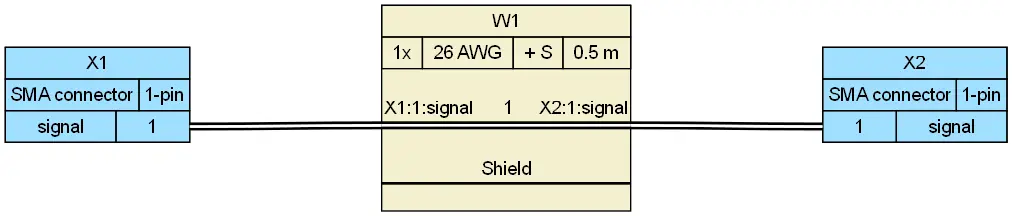
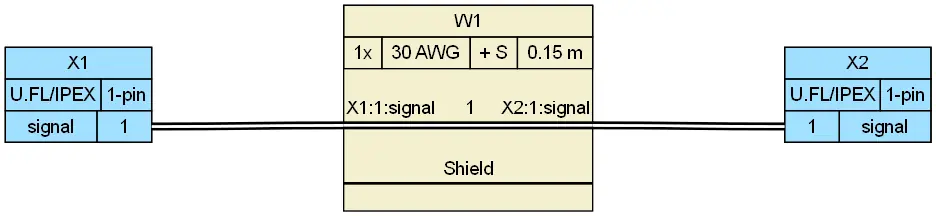
An SMA connector pigtail on a vibration-exposed asset needs a strain relief boot or reinforced transition; otherwise the coaxial braid and center conductor work-harden at the termination. A U.FL/IPEX pigtail in a dusty enclosure may need a locking or taped interface because snap-on retention alone may not survive service vibration. These conditions belong in the specification before pricing, not after a field failure.
Decide What Termination Quality Evidence to Require Before Approving a Golden Sample
A golden sample is necessary but not sufficient. One hand-built sample can hide process variation. For crimped or soldered pigtail terminations, IPC/WHMA-A-620[1] defines workmanship acceptance criteria that buyers should see in the supplier’s inspection record.
- Insulation clearance: The insulation must not be pierced or over-stripped at the crimp or solder joint.
- Pull force: The crimp terminal and AWG combination must meet the required conductor retention force.
- Conductor bellmouth: The crimp should show the correct conductor bellmouth without excessive flash or deformation.
- Strain relief placement: The strain relief must support the wire without pinching or pulling the conductor.
Ask to see crimp height inspection records, tensile pull-test data verified against IPC/WHMA-A-620 Class 2 or Class 3 limits (and terminal manufacturer tooling specs), plus 100% continuity test reports—not just one approved sample. Request the crimp tooling record or terminal part number to confirm the crimp terminal is matched to the wire gauge, not a generic substitute. For projects that grow into full wire harness manufacturing orders, the same evidence set should remain linked to the specific AWG and terminal combinations used on the floor.
Anticipate Field Failures Hidden by an Incomplete Pigtail Specification
An ambiguous pigtail line hides costs downstream. The following failure modes appear when the BOM line skips the mating connector and wire detail.
| Failure Mode | Root Cause Specification Gap | Physical Mechanism & Field Effect | Preventive Standard / Requirement |
|---|---|---|---|
| Contact Fretting & Intermittent Signal | Mating series & retention mechanism undefined | Micro-motion wears gold/tin plating under field vibration, increasing contact resistance and causing intermittent drops. | EIA-364-28 Vibration Test; Positive locking housing specification |
| Conductor Crimp Fatigue / Necking | AWG stranding & insulation OD omitted | Improper crimp anvil compression causes conductor strand severing or terminal bellmouth absence, leading to wire snap under dynamic bending. | IPC/WHMA-A-620 Crimp Height & Conductor Pull-force compliance |
| RF Signal Attenuation / High VSWR | Coaxial cable type & strip length unspecified | Center conductor deformation or damaged braided shield during manual stripping degrades impedance matching below 50 ohms. | Automated coaxial rotary strip inspection; Return loss / VSWR sweep testing |
| Reverse Polarity Insertion | Polarization / Keying not called out | Operator misaligns symmetrical headers in blind-mating scenarios, blowing power rail ICs upon power-up. | Keyed/polarized terminal housings; Mechanical poke-yoke alignment |
| Jacket Embrittlement & Dielectric Breakdown | Compound, flammability, & environmental rating missing | Standard PVC jacket degrades under hydraulic fluids, ozone, or UV, exposing live cores and causing short circuits. | UL 94V-0 / VW-1 rating; Cross-linked PE (XLPE) or PUR jacket specification |
These failures become retrofit cost after installation. A lower quoted price is not lower if the mating and wire details remain undefined. Before moving into a custom cable assembly, each of these gaps should be closed in the drawing and confirmed in the supplier’s written assumptions.
Pigtail Connector Supplier Quotation Decision Checklist
Use the table below as a screenshot-ready checklist. Enter the specification fields before accepting a quote. If any field is blank, return to engineering or ask the supplier to state assumptions in writing.
| Required Field | Buyer’s Specification Entry |
|---|---|
| Mating connector part number or series | _____________ |
| Contact count and pitch | _____________ |
| Wire gauge and length | _____________ |
| Insulation rating | _____________ |
| Keying / polarization | _____________ |
| Environmental requirements | _____________ |
Next action: attach this completed technical checklist alongside your 2D pinout drawing and 3D step file when submitting the RFQ. For custom cable assemblies and high-mix wire harnesses, EDOM Electronics provides engineering DFM reviews within 24 hours to identify terminal crimp tooling compatibility, alternative connector cross-references to mitigate component lead times, and functional pigtail prototyping in 3–5 business days prior to hard tooling sign-off.
Frequently Asked Questions
What is the difference between a pigtail connector and a standard cable assembly?
A pigtail connector has a connector at one end and open wire leads at the other, while a standard cable assembly usually carries connectors or terminated contacts at both ends. The pigtail is used as a transition into a larger wire harness or hard-wired junction.
Can a supplier quote a pigtail connector without the mating connector part number?
A supplier can quote conditionally, but the price and lead time remain indicative until the mating connector is defined. The quote should state every assumption in writing; otherwise the buyer risks approving a sample that cannot be repeated in production.
What wire gauge information should I provide for a pigtail connector RFQ?
Provide the wire gauge in AWG for each conductor, along with insulation type and finished wire length. AWG determines the crimp terminal size, conductor pull force, and current-carrying capacity, so it must be called out per circuit.
Does a U.FL/IPEX pigtail always need strain relief?
Not every U.FL/IPEX pigtail requires a separate strain relief boot, but the snap-on interface and thin coaxial cable benefit from retention and strain control. In vibration-exposed equipment, tape, a locking feature, or a reinforced cable transition reduces the risk of intermittent contact.
How do I confirm crimp quality before accepting a pigtail sample?
Request IPC/WHMA-A-620-aligned inspection records: crimp height measurements, pull force for the specific AWG and crimp terminal combination, insulation clearance verification, continuity testing, and appearance inspection. A golden sample alone does not prove that the production process can repeat the result.
Key Takeaways
- A pigtail connector is an assembly class, not a part number. Define the mating series, contact count, pitch, AWG, insulation, keying, and environment before requesting a quote.
- Compare JST connector, Molex, SMA connector, and U.FL/IPEX families by board mate, cable routing, and operating load—not by visual similarity.
- Evaluate the supplier’s proposal against vibration, temperature, flexing, oil, sunlight, and ingress conditions; require length tolerance, labeling, and strain relief in the quotation.
- Require IPC/WHMA-A-620-aligned evidence for crimped or soldered terminations, including crimp height, pull force, and tooling records—not just an approved sample.
- Use the supplier quotation decision checklist and require written assumptions for every blank field. Undefined mating and wire details become field retrofit risk after installation.
For additional guidance on connector selection and supply coordination, explore electronic connector sourcing options.