Direct answer: A TRS connector is a three-conductor cylindrical phone connector with separate Tip Ring Sleeve contacts, used to carry stereo unbalanced audio, balanced mono audio, or low-voltage control signals in audio equipment, instrumentation, and OEM devices. It is available in 1/4-inch, 3.5mm, and 2.5mm barrel diameters with multiple mounting styles and switched-contact variants.
At a Glance
A TRS line item cannot be approved by outline and pin count alone. Buyers need to confirm the mating plug part number, tip/ring/sleeve pinout map, switched-contact behavior, barrel diameter, mounting style, cable OD fit, and plating before releasing the BOM for production. Missing any one of these can turn a bench-passing part into a field return.
Do Either of These Situations Sound Familiar? Two TRS BOM Triggers That Stall a Production Release
A procurement specialist stares at a supplier BOM line that says only “TRS 3.5mm stereo jack” — no mating plug part number, no tip/ring/sleeve pinout, and no mounting detail — while engineering has flagged the line item for approval before a production release. Another common trigger is a buyer trying to find a drop-in replacement for an existing TRS jack after the original supplier went EOL, with only an internal part number and an old photo.
The hidden trap is treating “TRS” as a single standard interface. It is actually a family of three-conductor phone connectors with different barrel diameters, PCB/cable/panel mounting styles, switched-contact variants, and pinout conventions. The physical part may have the same drawing outline, but short the sleeve to chassis through the mounting bushing, or refuse the cable OD that the BOM approved, and nothing in the one-line RFQ will show that until the parts hit the bench.
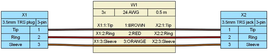
How to Verify TRS Pinout Before Approving a BOM Line Item
Confirm the mating plug part number and pinout map first. Tip, ring, and sleeve positions must match the PCB or cable schematic, not just the physical outline. A TRS connector can be wired several different ways, and assuming the consumer stereo convention creates first-article failures in pro-audio and industrial equipment.
Do not assume TRS means stereo. Mono audio (TS) uses tip and sleeve, with the ring zone merged into the sleeve body—which means plugging a TS plug into a TRS jack directly shorts the jack’s ring contact to ground. TRRS adds a fourth conductor for microphone or control lines, introducing a critical BOM trap between CTIA (Tip=L, Ring 1=R, Ring 2=GND, Sleeve=Mic) and OMTP (Tip=L, Ring 1=R, Ring 2=Mic, Sleeve=GND) pinout standards. For balanced audio, a single TRS connector carries a mono differential circuit (AES48 / IEC 60268-12), making the consumer stereo L/R/ground assumption fatal in professional or industrial instrumentation.
Also watch for switched contacts. A schematic symbol may show three contacts, but the physical jack can short sleeve to chassis through the mounting bushing or include tip/ring insertion switches for detection circuits. Those switch contacts are mechanical features that do not always appear on a simplified approval drawing.
| Configuration | Conductor assignment | Typical application |
|---|---|---|
| TS mono | Tip = signal, Sleeve = ground | Instrument and line-level unbalanced audio |
| TRS stereo unbalanced | Tip = left, Ring = right, Sleeve = ground | Headphones, consumer line-level interconnects |
| TRS balanced mono | Tip = hot (+), Ring = cold (−), Sleeve = ground/shield | Pro-audio patch bays, balanced interconnects |
| TRRS (CTIA vs. OMTP) | Tip = L, Ring 1 = R; Ring 2 / Sleeve = GND or Mic (standard-dependent) | Headsets, mobile audio, embedded I/O control |
How to Choose Between TRS Sizes and Mounting Styles Without Overloading the BOM
Compare the three common phone connector barrel diameters before locking the line item. The 1/4-inch phone connector is the larger, more robust option for pro-audio and stage equipment. The 3.5mm phone connector is the compact choice for consumer-facing or portable devices. The 2.5mm phone connector appears mostly in legacy or space-constrained designs. Each has different mating depth, retention force, and panel cutout requirements.
Select PCB, cable, or panel mount based on the actual enclosure, panel cutout, and cable strain relief, not just the drawing symbol. A PCB-mount jack that passes bench testing can still fail in the field if the panel cutout does not support the bushing, or if the plug’s strain relief cannot accept the approved cable OD.
Anchor mechanical interchangeability to EIAJ RC-5320A, also referred to as JEITA RC-5320A, for 3.5mm TRS dimensions and mating geometry. If the supplier’s part does not claim this standard, request a controlled mated-pair drawing before approval. Outline and pin count alone do not guarantee fit. EIA RS-453 can be referenced for phone connector mating dimensions where applicable, but it should not be treated as a single interchangeability guarantee across all manufacturers and mounting styles.
| Parameter | 1/4-inch (6.35mm) TRS | 3.5mm (1/8-inch) TRS | 2.5mm (3/32-inch) TRS |
|---|---|---|---|
| Nominal Sleeve OD | 6.35 mm ± 0.05 mm (0.250 in) | 3.50 mm ± 0.05 mm (0.138 in) | 2.50 mm ± 0.05 mm (0.098 in) |
| Mechanical Standard | EIA RS-453 / IEC 60603-11 | JEITA RC-5320A (EIAJ RC-5320A) | Manufacturer mated-pair drawing required |
| Typical Insertion / Withdrawal Force | 10 N – 40 N (gauge-dependent) | 3 N – 20 N initial | 2 N – 15 N initial |
| Typical Mating Cycles | 5,000 – 10,000 cycles | 3,000 – 5,000 cycles | 1,000 – 3,000 cycles |
| Typical Cable OD Range (Overmolded) | 5.5 mm – 8.0 mm | 2.5 mm – 4.5 mm | 1.8 mm – 3.2 mm |
| Primary Field Failure Mode | High lever-arm torque fracturing PCB solder joints | Tip detent spring fatigue & ring-to-sleeve shorting | Pin bending under radial side-load |
TRS BOM Approval Checklist: Go/No-Go Rows for Mating, Mounting, and Plating
Use this checklist before signing off on any TRS line item. Treat any “no” row as a hold. Outline and pin count alone are not enough to release a part for production.
| Check | Go condition | No-go trigger |
|---|---|---|
| Mating part number | Confirmed against supplier drawing | Plug or jack part number missing or unverified |
| Pinout map | Tip/ring/sleeve marked on both plug and jack | Schematic symbol shows three contacts without pinout |
| Switched-contact behavior | Verified for insertion detection or grounded-bushing configuration | Switch action not specified or assumed from outline |
| Mounting style | PCB, cable, or panel mount matches enclosure | Panel cutout or bushing layout conflicts with drawing |
| Cable OD compatibility | Strain relief and termination area accept approved cable | Plug strain relief too small for BOM cable OD |
| Plating and finish | Material, finish, and thickness match datasheet mating-cycle rating | Plating listed only as generic “gold” or “nickel” |
| Standard compliance | EIAJ/JEITA declaration or controlled mated-pair drawing | No standard claim and no mated-pair drawing |
When a datasheet omits switched-contact life or contact resistance stability, request the specific test condition (per EIA-364-23 low-level contact resistance) rather than assuming a generic mechanical cycle rating. In low-voltage microcontroller GPIO insertion-detection circuits (“dry circuits” operating at < 20 mV and < 100 mA where no wetting current exists to break through oxide films), tin or nickel switch contacts rapidly suffer from fretting corrosion, causing false plug-detect triggers long before mechanical spring fatigue occurs. Specify gold-flashed or minimum 0.2 µm (8 µin) selective gold plating over 1.27 µm (50 µin) nickel underplating for dry-circuit switch contacts.
How to Wire a TRS Connector Without Field Failures
Confirm the wiring diagram defines tip, ring, and sleeve per conductor color and cable OD before cutting. Do not let assembly rely on a technician’s memory of “consumer audio TRS,” because the same physical connector is used for balanced mono and switched-control circuits.
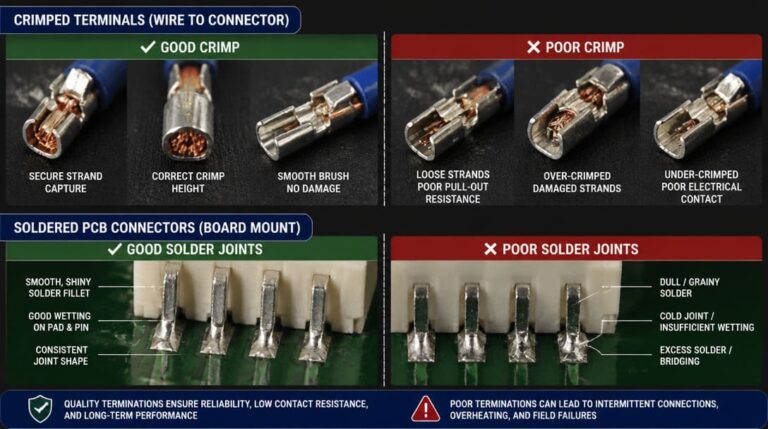
Follow IPC/WHMA-A-620[1] workmanship criteria for solder terminations. Control heat input, avoid disturbing the joint during cooling, and inspect for insufficient wetting or disturbed solder that leads to cold joints. Pay attention to thermal relief differences between signal and ground pads because high-thermal-mass sleeve lugs can produce cold solder joints when the process window is too short.
Strain relief architecture must match both the approved cable jacket OD and the assembly process. For field-wireable or mechanical plugs, an undersized boot crushes the dielectric while an oversized boot leaves the solder cups exposed to axial tension. For custom overmolded TRS cable assemblies, specify a dual-stage molding process: a rigid PE or PP inner mold to encapsulate the solder terminals and prevent Tip-to-Ring bridging during high-pressure injection, followed by a flexible PVC or TPE outer overmold with segmented flex-relief grooves. First-article samples should validate solder-joint encapsulation via cross-sectioning and verify axial pull-force retention (typically ≥ 45 N to 89 N for 1 minute per UL 817 / IPC/WHMA-A-620 pull-test guidelines) before production release.
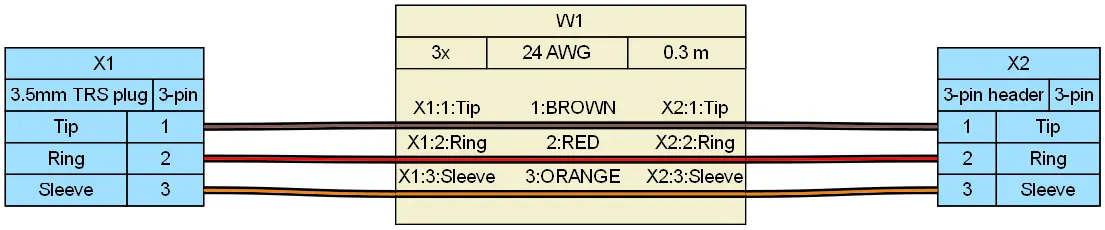
What Goes Wrong in the Field with TRS Connectors
Inverted L/R/ground wiring is the most common field complaint after an unverified replacement. The part fits, but channels are reversed or ground is lost, and the failure appears only after the product reaches the customer.
Cold solder joints from thermal relief differences may pass visual inspection but fail after thermal cycling, vibration, or repeated cable movement. Switched-contact fatigue appears in insertion detection circuits: a jack that works in a bench test may not recover after repeated insertions if the switch contact rating is ignored. Plating wear on high-cycle jacks causes intermittent audio or signal loss, so rely on datasheet mating-cycle ratings rather than unstated supplier claims.
These are field issues nobody mentions during quoting. They appear only as returns, rework, or first-article failures on the bench. For customers moving into wire harness manufacturing, the same pinout and strain relief checks should be locked into the assembly drawing before cutting begins.
From Datasheet Verification to Production Release: What to Ask a TRS Supplier Before Sign-Off
Request a controlled mated-pair drawing or an approved plug/jack combination when the supplier does not claim EIAJ RC-5320A or equivalent mating geometry. Ask for plating material and finish details, switched-contact life rating under the actual load, and solderability or termination documentation before sample approval.
Use first-article inspection to verify pinout continuity, insertion and extraction force, switch contact behavior, and fit with the actual cable OD and panel cutout. Confirm export packaging protects plated contacts and terminations during international shipping, warehouse receiving, and distributor inventory. This is where a supplier’s quality inspection and export packaging process becomes part of the approval decision, not an afterthought.
At EDOM Electronics, our engineering team eliminates TRS sourcing guesswork by cross-referencing your schematic against JEITA RC-5320A mating tolerances, validating switched-contact logic, and designing custom inner/outer overmolding tooling before cutting a single wire. Whether you need a drop-in EOL jack replacement or full custom TRS cable assemblies built to IPC/WHMA-A-620 Class 2/3 standards, we deliver DFM-verified prototypes in 3–5 days with 100% continuity, Hi-Pot (insulation resistance ≥ 100 MΩ at 500 VDC), and pull-force test reports.
Frequently Asked Questions
Is TRS the same as 3.5mm?
No. TRS describes the three-conductor Tip Ring Sleeve arrangement. It exists in 1/4-inch, 3.5mm, and 2.5mm barrel diameters. A 3.5mm TRS connector is only one size within the family.
Can a TRS connector carry balanced audio?
Yes. A TRS connector can carry a mono balanced signal with tip as hot, ring as cold, and sleeve as ground/shield. Do not assume the consumer stereo L/R/ground pinout when reviewing pro-audio or instrumentation schematics.
What does a switched contact in a TRS jack do?
A switched contact changes state when a plug is inserted. It may be used for insertion detection, signal routing, or speaker muting. The switch behavior must be verified against the actual circuit because it is often omitted from simple approval drawings.
What should I do if the supplier’s 3.5mm TRS jack does not reference EIAJ RC-5320A?
Request a controlled mated-pair drawing or an approved plug/jack combination. Outline and pin count alone do not guarantee mechanical fit, especially across panel mount, PCB mount, and cable mount variants.
What documentation should I ask for before TRS sample approval?
Ask for the mating plug part number, pinout map, mounting drawing, switched-contact specification, plating material and finish, and strain relief acceptance range for the cable OD. A supplier that supports OEM sourcing can also provide first-article inspection and export packaging confirmation.
Key Takeaways
- Never release a TRS BOM line on outline and pin count alone; confirm the mating plug part number and tip/ring/sleeve pinout map first.
- Treat TRS, TS, and TRRS as different interfaces with distinct conductor assignments, switched-contact behavior, and field failure modes.
- Use EIAJ RC-5320A / JEITA RC-5320A as the mechanical reference for 3.5mm TRS, and request a controlled mated-pair drawing when it is not claimed.
- Check cable OD compatibility, strain relief fit, plating detail, and switched-contact rating before sample approval.
- Use first-article inspection and IPC/WHMA-A-620 workmanship criteria to catch cold joints and inverted wiring before production release.
Need to lock down a flagged TRS BOM line or transition from off-the-shelf plugs to overmolded OEM wire harnesses? Explore our electronic connector sourcing and DFM support or send us your pinout drawing for a fast engineering review.