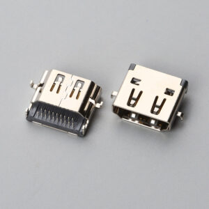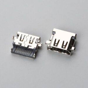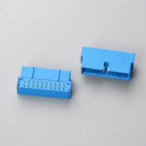
A design engineer closes the 3D CAD model and realizes the electrical schematic says nothing about how that bundle of wires survives vibration, heat, and assembly. The net list is complete, the pin labels match, and the routing sketch looks plausible — but the drawing still does not tell a supplier where bend radii must stop, which sections flex, what strain relief is required, or how the harness will be tested before shipment.
Direct answer: A wire harness design (as covered in Wire Harness Design Principles for Reliable OEM Cable Assemblies) is a buildable, testable, field-tolerant package that translates an electrical net list and 3D routing sketch into locked mechanical routing, flex-zone boundaries, insulation materials, connector orientations, pinout face views, service loops, strain relief, and production test points — not just point-to-point electrical connectivity.
This article goes deep into the decisions that separate a field-ready wire harness from an electrically correct drawing. It is written for procurement managers, OEM engineers, and distributor teams who need to finalize a harness design before prototype release without triggering a round of supplier clarification questions.
The Design-Room Gap: What the Schematic Doesn’t Define
A schematic captures which pins connect, but it does not define how the physical bundle behaves once it leaves the CAD screen. The design room tends to over-focus on net names and under-specify the mechanical conditions that determine whether a terminal stays seated, a jacket resists cracking, or a service loop absorbs vibration. Left open, these gaps transfer design responsibility to the harness board operator — who is not in a position to make material or routing decisions.
The areas most often left undefined include wire gauge and stranding class, insulation material for moving versus static zones, connector terminal part numbers, pinout verification against the physical connector face, bend-radius limits, service-loop placement, strain relief details, and test-point locations. Each of these becomes a supplier question that delays quoting and prototyping.
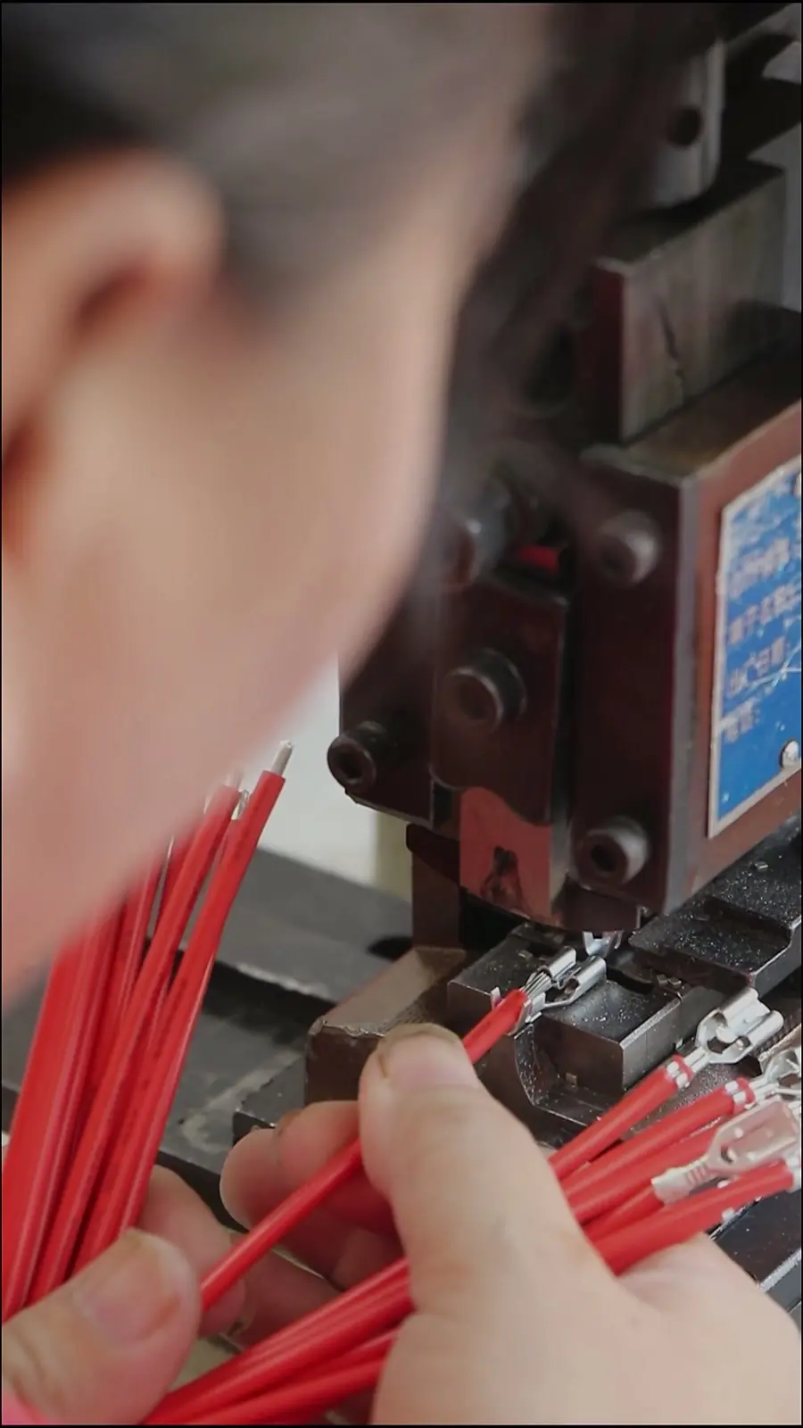
When moving from a 3D CAD concept to physical build, working with an engineering-focused manufacturer like EDOM Electronics bridges the gap through upfront DFM drawing redlines, authorized Molex/TE/JST connector cross-referencing (to bypass 16-week lead times without compromising terminal retention), and 3–5 day rapid prototyping. However, even the fastest NPI line can only lock repeatable process controls—such as automated cut-strip-crimp parameters and 1:1 test fixtures—when the upstream drawing package freezes the right mechanical and electrical decisions first.
Electrical Specification Decisions: AWG, Stranding, Insulation, and Color Control
The electrical design starts with the AWG wire gauge (detailed in Electrical Harness Design: Key Considerations for OEM Procurement), which must be specified by numeric size, stranding class, and insulation material. Do not allow an “equivalent” gauge substitution without an engineering change order because a gauge change alters voltage drop, bundle diameter, bend radius, and crimp-barrel fill. A design may look correct on paper yet fail in a flex zone if the selected wire has the correct current rating but the wrong stranding behavior.
Stranding class should be defined separately for static and moving sections. Fine stranding bends repeatedly without work-hardening as quickly; coarse stranding or solid conductors are acceptable only in static routes that never move during installation or service. Insulation material must also be tied to exposure: temperature, chemical contact, and repeated flexing. A static PVC jacket specified through a moving hinge area is a field failure waiting to happen.
Wire color codes need the same engineering discipline as pinouts. The design package should assign the base color, stripe, and print legend for every circuit. If a factory is allowed to substitute a mid-run color without an ECO, field service technicians lose traceability. Strip length and strip tolerance must also be called out because an undersized strip can leave stray strands outside the crimp barrel, while an oversized strip can create exposed conductor beyond the terminal bell mouth.
Mechanical Connection Decisions: Crimp Terminals, Pinout, and Retention
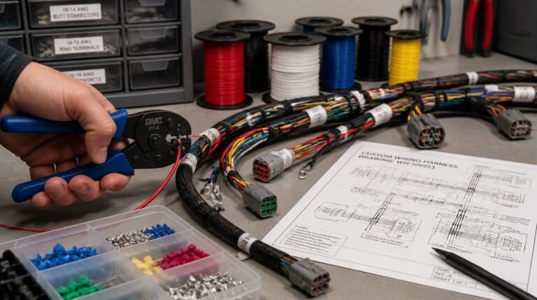
The crimp terminal is where most latent harness failures begin. The design package should specify the exact terminal part number, contact series, plating, crimp height, and pull-test requirement. Terminal selection cannot be left to the harness board operator, because connectors from the same family may have multiple compatible contacts with different plating, spring retention, and barrel-size grades.
Connector series and keying must match the contact family, and pinout should be verified against both the schematic and the physical connector face view. The physical face view matters because mirrored connector drawings, reversed row numbering, or swapped keying positions can produce a harness that is electrically correct according to the net list but physically impossible to plug into the mating board header.
Where the harness passes through abrasion, heat, or liquid zones, heat-shrink tubing or braided sleeving protects the bundle after assembly. Heat-shrink tubing referenced to UL 224[1] provides extruded insulating tubing performance and flame retardancy characteristics; braided sleeving adds mechanical abrasion resistance without making the bundle rigid. The choice between the two depends on whether the harness needs environmental sealing, mechanical cut-through resistance, or temporary accessibility during service.
Every connector exit and panel penetration must define its strain relief and grommet strategy. Strain relief prevents connector drag by fixing the wire relative to the connector body, while a grommet protects wires passing through sheet metal or enclosure walls. Without these details, vibration gradually works the terminal out of the housing or cuts the insulation on the panel edge.
For projects that later expand from a simple harness into an overmolded or jacketed assembly, the design-in sequence changes. Buyers can review custom cable assembly support to compare when a connector-to-connector cable makes more sense than a multi-branch harness.
Layout and Routing Decisions: Bend Radius, Service Loops, and Test Points
Routing is not decorative. It determines whether the harness can be installed without fighting the connector, whether the bundle clears hot surfaces, and whether repeated motion will fatigue the wire or the terminal. Static and flex zones should be routed separately, with bend radii marked according to wire and cable manufacturer limits. A bundle’s effective bend radius is larger than a single conductor’s, and routing that ignores bundle diameter allowance creates tight bends that stress the outer wires.
Service loops absorb vibration, thermal expansion, and assembly tolerance. When a connector is mounted on a moving component or a panel is removed during maintenance, the service loop gives the bundle slack without pulling directly on the terminal. The design should show where the loop sits, how much slack is required, and how the loop is dressed against the harness board.
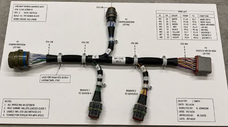
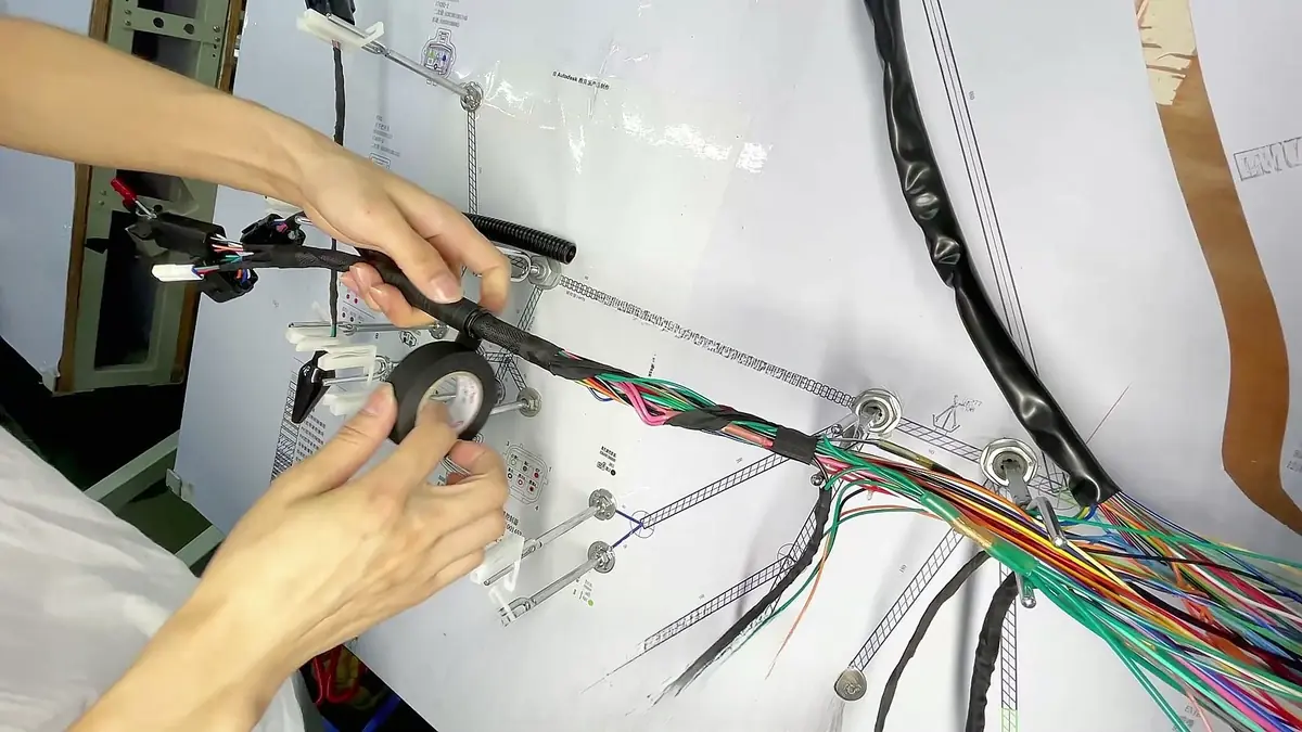
The harness board is the physical 1:1 routing fixture that controls repeatable production. The board layout should define breakout points, dressing positions, bundle lengths, and branch angles. If the design package only contains a schematic, the production team invents a board layout — and every board iteration risks drifting from the approved sample. Test points for continuity, hipot, and final appearance inspection should also be placed on the drawing, not added as a post-build afterthought.
Beyond basic pathing, a production-grade harness board layout must lock three critical geometric rules to prevent assembly fitment issues:
- Breakout angles and tie-wrap spacing: Branch breakouts should exit the main trunk at 30° to 90° with dual tie-wraps or spot-taping anchoring the T-junction. Anchor ties along straight runs every 100 mm to 150 mm so individual wires cannot separate or snag during installation.
- Inline splice placement: Keep ultrasonic welds and open-barrel splice joints in straight, static trunk sections—at least 40 mm to 50 mm away from bend radii, grommets, and connector backshells—because splices create rigid hard spots that fracture under flexing.
- Dimensional tolerance stack-up: Specify asymmetric tolerances (typically +5 mm / -0 mm on critical branches) rather than tight negative tolerances. A harness that is 5 mm long can be absorbed by a service loop, whereas a harness that is 3 mm short puts constant tensile load on the terminal locks.
Wire Harness Design Deliverables: A Screenshot-Ready Checklist
The design package is release-ready only when every design element has a specified value, method, and acceptance criterion. The table below functions as a pre-release gate: any row left undefined stops the drawing from moving to the supplier.
| Design Element | What Must Be Specified | Engineering Baseline / IPC-A-620 Target | Field Failure If Left Undefined |
|---|---|---|---|
| AWG wire gauge & stranding | Numeric AWG + stranding class + UL AWM style | Static: Class B (7/19 strands); Dynamic flex: Class K/M (fine/extra-fine strands, UL 758) | Voltage drop, thermal overload, or premature conductor fracture in flex zones |
| Crimp terminal | MPN + contact series + plating + crimp height + pull-force limit | Crimp height tolerance typically ±0.03–0.05 mm; pull test per IPC/WHMA-A-620 Table 4-1 / UL 486A | Terminal back-out, fretting corrosion, or high contact resistance |
| Strip length & bellmouth | Nominal strip length (mm) + tolerance + conductor brush projection | Conductor brush visible 0.5–1.0 mm past conductor crimp barrel; bellmouth 0.2–0.5 mm (IPC Class 2/3) | Birdcaged strands, insulation crimped into contact area, or short-circuit whiskers |
| Heat-shrink tubing | Material class + shrink ratio + adhesive lining + recovery length | UL 224 VW-1 rated; 2:1 (dry indoor) or 3:1 / 4:1 dual-wall adhesive-lined (moisture/splice sealing) | Moisture wicking, galvanic corrosion at ultrasonic splices, or abrasion at breakouts |
| Braided sleeving | Material (PET/Nylon/Nomex) + nominal ID + optical coverage + end termination | ≥80% braid coverage; hot-knife cut ends captive under heat-shrink or tie-wraps per IPC-A-620 | Frayed braid ends, cut-through chafing against sheet-metal brackets |
| Bend radius | Minimum radius per bundle OD + static vs. dynamic transition markers | Static routing: ≥3× to 6× bundle OD; Dynamic flexing: ≥8× to 10× bundle OD (Coax/HV/Fiber: ≥10×) | Outer-wire tensile stress, insulation crazing, and impedance shift in twisted pairs |
| Service loops & length tolerance | Loop coordinates + slack length + branch dimensional tolerances | 25–50 mm slack at serviceable panels; overall length tolerance ±1.5 mm to ±3.0 mm (or ±1% on long trunks) | Tension on terminal crimps under vibration or inability to mate during chassis assembly |
| Pinout & electrical test points | Mating vs. rear wire-insertion view + continuity/HiPot test parameters | 100% continuity (<50 mΩ threshold); Dielectric Withstand / Insulation Resistance (e.g., 500V–1500V DC, >100 MΩ) | Mirrored pinout reversal, intermittent shorts, or dielectric breakdown in humid environments |
If the table exposes undefined rows, treat them as a release gate. Send the design package to EDOM for drawing review, connector matching, and sample confirmation before prototyping so the supplier can quote against a complete build definition rather than returning the drawing with clarification questions.
Field Failure Modes That Trace Back to Design Gaps
The gap between a hand-built prototype and volume production often appears in predictable ways. These failure modes all have a common root: the design package never froze the decisions that keep production identical to the approved sample.
Flexural fatigue and jacket cracking in moving zones. Standard semi-rigid PVC insulation selected for a dynamic hinge or articulation zone undergoes mechanical stress concentration and plasticizer migration, leading to insulation cracking and copper strand work-hardening at the point of maximum flexing. Meanwhile, true thermal runaway occurs when an undersized AWG gauge or high-resistance crimp generates excessive I2R heating inside a tightly bundled loom. Both defects pass continuity testing at incoming inspection because failure only manifests under cyclic motion or full electrical load.
Birdcaged strands at the crimp. A missing strip-length callout or tolerance leaves stray wire strands outside the crimp barrel. The terminal crimps onto fewer strands than designed, increases resistance, and creates a whisker risk. Production technicians cannot correct a tolerance that was never defined.
Connector drag or pin retention loss. The contact series and retainer are not specified, so the assembly uses whatever terminal is available on the board. Under vibration or repeated insertion force, the terminal backs out of the housing. The harness is then blamed for a connector problem that began with an unspecified contact family.
Mid-run color swaps without an ECO. A factory substitutes a wire color because the original part number is not in stock or a stripe is unavailable. The change is not recorded because the design package did not require an ECO for color changes. Field service later chases the wrong circuit during diagnostics.
The golden sample trap. A hand-built pre-production harness passes all inspections because a senior technician hand-selected terminals, dressed the bundle carefully, and tested every circuit. Volume production then drifts into pinout errors, wrong connector series, off-spec wire gauge, or substituted jacket material. The approved sample looked perfect, but the design package never locked build tolerances, test points, and approval criteria for repeatable production.
Design Review Sequence Against IPC/WHMA-A-620
IPC/WHMA-A-620 defines acceptance criteria for cable and wire harness assemblies and establishes three workmanship classes with increasing inspection and documentation rigor. Before releasing a design package to a supplier, the following review sequence verifies that the package can be built and accepted against those workmanship expectations.
- Freeze the net list and pinout. Verify every connector face view against the schematic. The face view orientation must match the mating connector, not just the symbol on the drawing.
- Verify material part numbers. Check AWG wire gauge, insulation type, crimp terminals, heat-shrink tubing, braided sleeving, grommets, and strain relief components. Each part should have a single manufacturer part number or an approved equivalent with engineering sign-off.
- Check bend radii and flex-zone boundaries. Move static PVC or undersized wire out of moving zones. Mark where flexing begins and ends so the harness board operator can dress the bundle accordingly.
- Confirm service loops and strain relief. Every termination and panel exit should have a defined slack path and a method for anchoring the wire relative to the connector body or panel edge.
- Define required test points and acceptance limits. Continuity, hipot, and final appearance inspection should be marked on the harness board layout, with pass/fail criteria tied to the workmanship class.
- Run the drawing package through a workmanship review. Check the design against IPC/WHMA-A-620 acceptance concepts and lock an ECO process before prototype release. No supplier should receive a package with open color substitutions, undefined strip lengths, or unspecified terminal part numbers.
Once the design package passes this sequence, the build becomes repeatable because the production controls reference the same decisions the sample approval verified.
Next Step: From Design Package to Production-Ready Harness
With bend radii, service loops, strain relief, color codes, and test points frozen, a supplier can quote accurately and build repeatably. The design package no longer depends on a senior technician hand-adjusting every unit. That is the difference between a drawing that asks for a quote and a drawing that is ready for production.
For readers who have completed the design package, the next stage moves into manufacturing review, tooling verification, connector handling, and first-article approval. Learn more about wire harness manufacturing support and how a production-coordinated supplier can review the drawing against build feasibility before cutting wire.
During that production loop, incoming connector verification, continuity testing, appearance inspection, and export packaging become the visible controls that keep volume shipments consistent with the approved sample. See quality inspection and export packaging support for the inspection sequence buyers should expect before shipment preparation.
Frequently Asked Questions
Why do wire harness suppliers ask for bend radius and service loop details?
Suppliers ask for these details because routing determines whether the bundle survives installation and operation. Bend radius limits prevent wire fatigue and insulation cracking, while service loops absorb vibration, thermal expansion, and assembly tolerance without pulling stress into the terminal or connector.
What is the difference between a harness schematic and a wire harness design package?
A schematic shows electrical connectivity. A design package also specifies wire gauge and stranding, insulation material, crimp terminal part numbers, connector orientation, pinout face views, bend radii, service loops, strain relief, color codes, harness board routing, and test points. Only the design package gives the supplier enough information to build repeatably.
What does IPC/WHMA-A-620 cover for wire harness assemblies?
IPC/WHMA-A-620 defines acceptance criteria for cable and wire harness assemblies and establishes three workmanship classes with increasing inspection and documentation rigor. It provides a common reference for judging solderless crimp quality, wire dress, harness routing, insulation placement, and assembly workmanship.
How do you prevent a hand-built prototype from passing while volume production drifts?
Freeze every build decision in the design package: AWG wire gauge, stranding class, insulation type, crimp terminal part number, crimp height, color codes, strip lengths, bend radii, service loops, strain relief, and test points. Then require an ECO for any substitution. The prototype should be approved only against the same criteria that volume production will be inspected against.
When should a wire harness design package be sent for drawing review?
The design package should be sent for drawing review after the deliverable checklist has no undefined rows. If the AWG wire gauge, crimp terminal, heat-shrink tubing, braided sleeving, strain relief, grommet, harness board layout, service loops, bend radius, color code, and pinout test points are all specified, the supplier can proceed to connector matching and sample confirmation instead of issuing clarification questions.
Key Takeaways
- A wire harness design must lock mechanical routing, flex zones, insulation material, connector orientation, pinout verification, service loops, strain relief, and production test points — not just electrical connectivity.
- AWG wire gauge, stranding class, insulation type, color codes, and strip tolerances should never be left open for the harness board operator to decide mid-run.
- Crimp terminal part numbers, plating, crimp height, and pull-test requirements prevent terminal back-out and high-resistance crimps in service.
- Field failures such as flexural fatigue, birdcaged strands, connector drag, and the golden sample trap all trace back to design gaps, not to poor production workmanship alone.
- A release-ready design package passes a deliberate review sequence informed by IPC/WHMA-A-620 workmanship concepts before it reaches the supplier.