Direct answer: A DC connector is the physical interface that carries direct current between a power source and a device, covering barrel-type plugs and jacks, PCB-mounted power jacks, panel-mount jacks, and inline connectors. It is a category of interconnects(see our What Is a Connector? A Practical Overview for OEM Buyers), not a single standardized mating interface.
A technician pulls a replacement part from the shelf, sees “DC connector” on the label, and plugs it in — only to find the barrel fits but the center pin rattles and the device powers down when the cable flexes.
Direct Answer: A DC Connector Is a Category, Not a Single Mating Standard
That production-floor failure is not an isolated incident. “DC connector” appears on BOMs, equipment manuals, and replacement part lists, but the term masks the fact that multiple connector families can carry DC power through different mechanical interfaces. A barrel connector uses a hollow cylindrical outer sleeve and an inner pin to make electrical contact. A DC power jack is the receptacle, often mounted on a PCB or panel, that receives the plug. A coaxial power connector may share the same cylindrical geometry but is not automatically interchangeable with every barrel-style part, because mating depth, switch contacts, and pin sizing can differ.
Because the label is generic, identifying a replacement requires dimensional and mechanical specification, not just a part-number lookup. Two visually identical DC connectors can be incompatible if their center pin diameters, barrel lengths, mounting footprints, or internal switch configurations differ.
Why “DC Connector” on a Drawing Is Not Enough: Plug vs Jack and Mounting Style
Any DC connector BOM line or drawing must distinguish the plug — usually cable-end — from the jack — usually equipment-, PCB-, or panel-mounted. Retention and wear occur mainly at the jack’s center pin and spring contact, so mating compatibility is not symmetric. A cable-end plug that fits the outer sleeve can still fail to seat properly inside the jack if the center pin engagement is wrong.
Barrel type means a cylindrical outer sleeve and an inner pin. Matching only the outer sleeve diameter is not enough because the same outer sleeve can accept different center pin diameters. A nominally 5.5 mm outer sleeve plug typically pairs with either a 2.1 mm or 2.5 mm inner diameter (ID) to mate with the jack’s corresponding center pin outer diameter (OD). A cable plug with a 5.5 mm outer sleeve and a 2.5 mm inner diameter will mechanically insert into a jack designed for a 2.1 mm center pin, but the center pin will rattle, causing intermittent electrical contact or contact resistance spikes due to insufficient spring contact normal force. Conversely, a 2.1 mm ID plug cannot physically push onto a 2.5 mm center pin.
Mounting style changes the footprint and mechanical retention. PCB through-hole, surface-mount, panel-mount with nut, and inline cable assembly all require different board spacing, panel cutouts, and strain relief. A panel-mount DC power jack with a threaded body cannot replace a through-hole PCB version without redesigning the enclosure and termination points.

Decision-Critical Parameters: Barrel Dimensions, Pin Size, Insertion Depth, and Ratings
Inner and outer barrel diameters define the primary mechanical interface. The outer sleeve diameter controls whether the plug enters the jack, while the inner diameter is the mating surface for the center pin. The common 2.1 mm inner diameter paired with a 5.5 mm outer sleeve is widely used, but it is not a universal replacement for every part with the same nominal outer diameter.
Center pin diameter must match the jack contact precisely. A slight mismatch produces intermittent contact or no electrical connection even when the barrel appears to seat. Insertion depth and retention spring position determine whether the plug bottoms out at the correct point. Too short leaves the plug loose; too long can miss the retention spring or prevent the jack’s internal switch from toggling.
Current and voltage ratings are limited by contact area, plating thickness, and spring force. Verify actual load current with margin, not just the nameplate voltage. Many DC power jacks include a normally closed switch contact for battery cutoff or signal routing. The plug must reach the correct insertion depth to open or close that switch reliably.
Polarity is not universal. Center-positive is common on many consumer and industrial adapters, but center-negative appears on some audio, instrumentation, and legacy equipment. The equipment label and schematic must be checked, because reversed polarity can damage the load even when the mechanical fit is correct.
Standard DC Barrel Dimensions & Engineering Limits
| Standard / Nominal Type | Plug Barrel OD (mm) | Plug Inner ID / Jack Pin OD (mm) | Common Barrel Lengths (mm) | Typ. Current Rating | EIA-364 Contact Resistance Baseline |
|---|---|---|---|---|---|
| EIAJ-01 (Voltage Class 1: ≤3.15V) | 2.35 ±0.05 | 0.70 ±0.05 | 9.5 ±0.5 | 2.0 A max | ≤30 mΩ initial |
| EIAJ-02 (Voltage Class 2: 3.15–6.3V) | 4.00 ±0.05 | 1.70 ±0.05 | 9.5 ±0.5 | 2.0 A max | ≤30 mΩ initial |
| EIAJ-03 (Voltage Class 3: 6.3–10.5V) | 4.75 ±0.05 | 1.70 ±0.05 | 9.5 ±0.5 | 2.0 A max | ≤30 mΩ initial |
| EIAJ-04 (Voltage Class 4: 10.5–13.5V) | 5.50 ±0.05 | 3.40 (Center Pin in Plug) | 9.5 ±0.5 | 2.0 A max | ≤30 mΩ initial |
| Industry Standard 5.5/2.1 | 5.50 +0.05/-0.10 | 2.10 +0.10/-0.00 (Plug ID) | 9.0 / 9.5 / 11.0 / 14.0 | 2.0 A – 5.0 A (Contact dependent) | ≤30 mΩ (Tested per EIA-364-23) |
| Industry Standard 5.5/2.5 | 5.50 +0.05/-0.10 | 2.50 +0.10/-0.00 (Plug ID) | 9.0 / 9.5 / 11.0 / 14.0 | 2.5 A – 10.0 A (Heavy-duty clip) | ≤30 mΩ (Tested per EIA-364-23) |

Standardization vs De Facto Dimensions: EIAJ RC-5320A and Vendor-Defined Barrel Sizes
EIAJ RC-5320A (superseded by JEITA RC-5320A, harmonized partly under IEC 60130-10) standardizes DC barrel power interfaces into five specific voltage classes with indexed polarities and keyed pin geometries to prevent overvoltage insertion. For internationally used coaxial power connectors, IEC 60130-10 covers some mechanical patterns, but many globally used barrel dimensions remain vendor-defined rather than governed by one universal standard.
The difference between a standard dimension and a manufacturer part number matters. Matching the nominal outer and inner diameters does not guarantee the same electrical performance or mechanical retention, because tolerances, plating, insertion depth, and switch configuration can vary between manufacturers. A part labeled only as “5.5/2.1” may be mechanically compatible with some jacks but electrically or mechanically wrong for a specific PCB footprint or switch arrangement.

Field Failure Modes: What Actually Happens When DC Connectors Are Mismatched
Mismatched DC connectors do not always fail immediately at incoming inspection. They often pass visual checks and then fail on the production line or in the field. The table below summarizes common failure modes, their mechanical root causes, and field consequences.
| Symptom | Mechanical Root Cause | Field Consequence |
|---|---|---|
| Intermittent power drop when cable moves | Center pin diameter too small for jack contact | Device resets or shuts down under vibration or handling |
| Plug slides out under its own cable weight | Barrel length too short; retention spring never engages | Unexpected power loss and possible equipment damage |
| Device does not recognize adapter or switches incorrectly | Barrel length too long; plug bottoms out before jack switch actuates at correct insertion depth | Battery cutoff or signal routing fails, causing incorrect power draw |
| Localized heating at the jack | Contact resistance from plating wear or reduced contact area | Weakened solder joints, softened jack body, or intermittent shutdown |
| Permanent damage to jack contact | Center pin diameter too large, deforming the jack spring contact | Future proper plugs cannot mate reliably |
DC Connector Verification Checklist Before You Order
The following verification sequence prevents the most common DC connector mismatches. The checklist assumes access to the actual plug and jack samples, not just a data sheet drawing.
- Confirm center pin and barrel dimensions with the actual plug and jack samples. Do not rely on the outer barrel diameter alone; verify the inner diameter and pin size using calipers or a known mating connector.
- Confirm insertion depth and retention. The plug should bottom out at the intended position and stay retained under moderate cable pull without excessive force.
- Confirm jack switch configuration if present. Measure continuity at open and closed positions using the actual plug, not a generic test pin, to verify that the internal switch toggles at the correct insertion depth.
- Confirm rated current is above the actual load with margin, accounting for inrush current and contact resistance at the expected operating temperature.
- Confirm the PCB footprint or panel cutout matches the mounting style: through-hole, surface-mount, panel nut, or inline.
- Confirm polarity marking matches the system. Check whether the center pin is positive or negative on the equipment label and schematic, and compare it with the replacement connector’s wiring orientation.
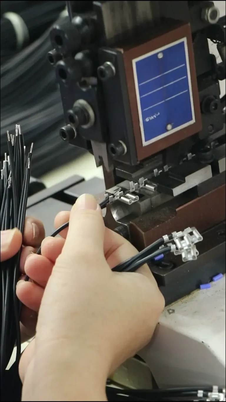
Once mechanical dimensions and switch actuation are verified on bench prototypes, OEM scaling requires Design for Manufacturability (DFM) reviews on cable termination. Custom cable assemblies demand proper overmolding tooling (evaluating PVC vs. TPU vs. Low Pressure Molding/Polyamide) to protect internal solder joints from strain relief failure during IPC/WHMA-A-620 pull tests. Engineering teams should request mold flow simulations and 3–5 day rapid prototyping for first-article inspection (FAI) before committing hard-tooling NRE budgets.
From Verified DC Connector to Stable Supply: What to Review Before Production
Once the DC connector is verified, the remaining work is making the transition from a confirmed sample to stable production. Prepare the sample plug and jack, measured dimensions, current and voltage margin, polarity marking, and mounting style for sourcing or drawing review. For custom cable assemblies, include termination method, wire gauge, strain relief, and labeling requirements in the same package as the connector data. For wire harnesses, route and sleeve specifications should be documented alongside the connector selection. Before shipment, confirm inspection and export packaging criteria so the verified connector reaches the production line without damage or dimensional drift.
For broader connector families beyond DC power, review electronic connector options for board-to-board, wire-to-board, and custom cable assembly applications.
Frequently Asked Questions
What is the difference between a 2.1 mm and 2.5 mm inner diameter DC connector?
A 2.1 mm inner diameter means the jack’s center pin mating hole is designed for a 2.1 mm center pin. A 2.5 mm inner diameter accepts a larger pin. Even when both use the same 5.5 mm outer sleeve, the pin sizes are not interchangeable — the plug will either rattle and cause intermittent contact or will not seat properly.
How do I identify the polarity of a DC connector?
Check the equipment label, schematic, or original adapter. The polarity marking typically shows whether the center pin is positive or negative. A center-positive marking means current flows from the center pin to the outer barrel; center-negative reverses that. Never assume polarity based on barrel dimensions alone.
What does EIAJ RC-5320A cover?
EIAJ RC-5320A standardizes certain DC power connector configurations for the Japanese market. It defines voltage classes, current classes, and dimensional requirements to reduce the risk of mating mismatches. It does not cover every barrel connector used globally, so vendor-specific dimensions still require part-level verification.
Can I replace a 5.5 mm outer sleeve connector with any other 5.5 mm barrel connector?
No. A 5.5 mm outer sleeve can mate with multiple center pin diameters, barrel lengths, and jack switch configurations. The replacement must match not only the outer sleeve dimension but also the inner diameter, insertion depth, mounting style, and electrical rating.
How do I source replacement DC connectors without a full part number?
Measure the outer sleeve diameter, inner diameter, insertion depth, and mounting style from the original sample. Document polarity, current rating, and any internal switch function. Suppliers such as EDOM Electronics can support requirement review, connector matching, and sample confirmation when a full part number is unavailable.
Key Takeaways
- A DC connector is a category of interconnects, not a single mating standard. Barrel plugs, DC power jacks, and coaxial power connectors share geometry but differ in pin size, depth, and switch behavior.
- The outer barrel diameter alone is insufficient for compatibility. Verify center pin diameter (e.g., 2.1 mm inner diameter vs 2.5 mm) and insertion depth with actual samples.
- Polarity is not universal. Confirm center-positive or center-negative markings on the equipment and schematic before connecting or sourcing.
- Standards such as EIAJ RC-5320A and IEC 60130-10 reduce mismatch risk for some markets, but many common barrel sizes remain vendor-defined and require part-level verification.
- Before production, complete a DC-specific verification checklist covering dimensions, retention, switch contacts, current margin, footprint, and polarity, then hand off confirmed data for sourcing and packaging.
Explore electronic connector options for board-to-board, wire-to-board, and custom cable assembly applications.