Direct answer: A spade connector is a general trade term for a flat, spade-shaped crimp terminal used to create a separable electrical connection — see our What Is a Connector? A Practical Overview for OEM Buyers; it can mean an open-slot fork terminal for screw or stud mounting, a solid male blade terminal, or a female quick-disconnect receptacle. A spade connector is only confirmable as a BOM line when tab width, tab thickness, gender, insulation style, and locking retention are defined.
At a Glance
A specification that says only “spade connector, 6.3 mm” is not ready for quotation or production. Procurement and engineering must first decide whether the part is a fork terminal, a male blade terminal, or a female quick-disconnect receptacle, then lock the tab width, tab thickness, insulation material, stud size where applicable, AWG range, plating, and mating part number. Use the decision table below as a go/no-go gate before any terminal is sampled or released.
Is ‘Spade Connector’ Specific Enough to Approve? Ask These Two Questions First
A procurement manager receives a BOM line that says “spade connector, 6.3 mm” with no tab thickness, no insulation style, and no mating part number. A design engineer is handed a harness repair sketch in which fork terminals, ring terminals, and quick-disconnect receptacles are all casually labeled “spade.” Both face the same problem: the visible width has become the only checked dimension, while the mechanical family behind the terminal remains undecided.
That assumption fails because a spade connector can be a fork terminal with an open U-slot, a blade terminal with a solid male tab, or a female quick-disconnect receptacle that receives that tab. Each belongs to a different mating system. A 6.3 mm fork terminal sits under a screw; a 6.3 mm male blade requires a matching female receptacle with the correct spring retention angle and tab-thickness accommodation. Visually similar parts do not interchange.
Before approving any terminal line, two questions must be answered. Is the part a fork terminal, a male blade terminal, or a female receptacle? And what is the exact tab thickness class, not just the tab width, with which mating part number or dimensional sheet will be used for confirmation? Anything short of that is an RFQ that cannot be confirmed.
Lock Down Tab Width, Tab Thickness, and Gender Before Approving the Terminal
Tab width is the easiest dimension to read and the least complete specification. Common metric families include 2.8 mm, 4.8 mm, 6.3 mm, and 7.8 mm, but each family may appear in multiple tab thickness classes, typically 0.5 mm and 0.8 mm. A 4.8 mm male blade designed for a thicker tab has a different spring retention fit inside its receptacle than a 4.8 mm terminal designed for a thinner tab.
Gender must be stated explicitly on the BOM. A male blade terminal mates only with a matching female quick-disconnect receptacle from the same width and thickness family. A fork terminal has no mating blade; it slides under a screw, stud, or terminal block clamp. When the BOM says only “spade,” these two installation paths remain unresolved.
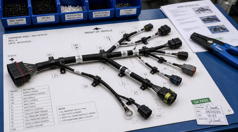
Before quoting or tooling starts, the specification should read as one of the following: male blade terminal, female quick-disconnect receptacle, or fork terminal, followed by the exact width and thickness class. For a custom cable assembly project, this information belongs in the drawing review and should be checked against the mating component before the design is frozen. It is common for visually close families to mix during procurement, which then creates loose retention, intermittent contact, and thermal-cycle failures that do not appear until field use.
Choose Insulation Style and Stud Size After Confirming Installation Conditions
Insulation is a performance decision, not simply a color choice. A vinyl insulation sleeve offers lower cost, good flexibility, and adequate protection for general interior wiring. Nylon insulation provides higher abrasion resistance and better performance where heat or mechanical contact is more severe, such as engine-compartment or high-vibration harness sections. The correct insulation material depends on the harness routing, surrounding surfaces, and temperature profile of the equipment.
For fork terminals, stud size is a separate and non-negotiable field. Common imperial stud sizes include #6, #8, and #10, with metric equivalents available for many terminal blocks and busbar connections. The open U-slot must match the screw or stud diameter closely enough for the terminal to seat flush under the clamping surface; too large a slot reduces contact area, while too small a slot will not seat at all.
Wire gauge compatibility completes the set. The crimp barrel on any spade-style crimp terminal is sized for a defined AWG range. If the harness conductor falls outside that range, the crimp will either leave loose strands outside the barrel or crack the barrel wall during compression. The BOM line should therefore carry insulation material, stud size where applicable, and the exact AWG range on the crimp barrel as one package. A missing field in this group becomes a line-stop or a warranty risk later.
Verify Mating Compatibility: Which Receptacle Series Actually Fits the Blade?
A 6.3 mm female receptacle from one series does not automatically grip a 6.3 mm male tab correctly if the tab thickness differs even a fraction of a millimeter. Tab width may match, but spring retention angle, locking lance, and base-plate geometry control whether the connection remains gas-tight and vibration-resistant. These features live inside the female receptacle and cannot be verified by a tape measure across the blade.
Before approving the BOM, check the mating part number or dimensional sheet against the actual blade or receptacle. For quick-connect terminals where applicable, UL 310[1] provides dimensional and retention requirements that can be used as a reference. For crimped harness work, IPC/WHMA-A-620 supplies acceptance criteria for the finished assembly. Neither accepts a visual width check as sufficient evidence of mechanical compatibility.
For fork terminals, the verification challenge shifts away from spring retention. The open U-slot must sit cleanly under the screw head without interfering with adjacent terminals, standoffs, or connector bodies. The slot width, stud size, and insulation profile should be checked together on the assembly drawing, because a terminal that fits the screw may still be impossible to install once adjacent wires are present.
Use This Spade Connector Decision Table to Force a Confirmable BOM
The table below is a working audit tool, not a product selection chart. It maps common tab width and thickness families to typical mating forms, insulation choices, and verification references. The final column is a go/no-go gate: if tab width, tab thickness, gender, insulation, and locking feature are not all stated, the line is marked no-go and cannot proceed to quotation or sampling.
| Common tab width × thickness family | Typical mating receptacle or terminal form | Insulation/sleeve options | Minimum retention-force verification | BOM go/no-go |
|---|---|---|---|---|
| 2.8 mm × 0.5 mm | Female quick-disconnect receptacle in same 2.8 mm family | Vinyl sleeve, nylon sleeve, or uninsulated with separate sleeve | IPC/WHMA-A-620 acceptance class plus terminal manufacturer pull-force data | No-go unless width, thickness, gender, and insulation are defined |
| 4.8 mm × 0.5 mm | Female quick-disconnect receptacle or fork terminal for screw/stud mounting | Vinyl insulation or nylon insulation depending on routing | IPC/WHMA-A-620 acceptance class plus manufacturer tooling data | No-go without explicit gender and stud size where fork |
| 4.8 mm × 0.8 mm | Female quick-disconnect receptacle; blade terminal for heavier conductor | Nylon insulation preferred for abrasion resistance | IPC/WHMA-A-620 acceptance class plus manufacturer pull-force data | No-go if tab thickness is not confirmed |
| 6.3 mm × 0.8 mm | Female quick-disconnect receptacle; common in appliance and automotive harness work | Vinyl insulation, nylon insulation, or uninsulated | IPC/WHMA-A-620 acceptance class plus manufacturer retention data | No-go unless mating part number or dimensional sheet is listed |
| 7.8 mm × 0.8 mm | Female quick-disconnect receptacle for higher-current circuits | Nylon insulation or uninsulated with harness sleeve | IPC/WHMA-A-620 acceptance class plus manufacturer pull-force data | No-go unless wire AWG and barrel compatibility are confirmed |
| Fork terminal, stud-sized | No mating blade; seats under screw or stud | Vinyl insulation or nylon insulation; #6, #8, #10, or metric stud slot | IPC/WHMA-A-620 acceptance class; verify slot-to-stud fit | No-go unless stud size, insulation, and AWG range are defined |
To use the table, take the original BOM line “spade connector, 6.3 mm” and ask the supplier to fill the missing cells. If the supplier cannot state a tab thickness or mating series, the safest outcome is to stop the line before sampling rather than approve a look-alike part. The go/no-go cell is not a design suggestion; it is the difference between a confirmable specification and an unverified guess.
Specify Crimp Tooling and Pull-Force Verification Before Production Release
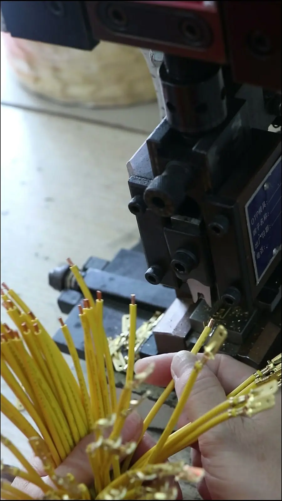
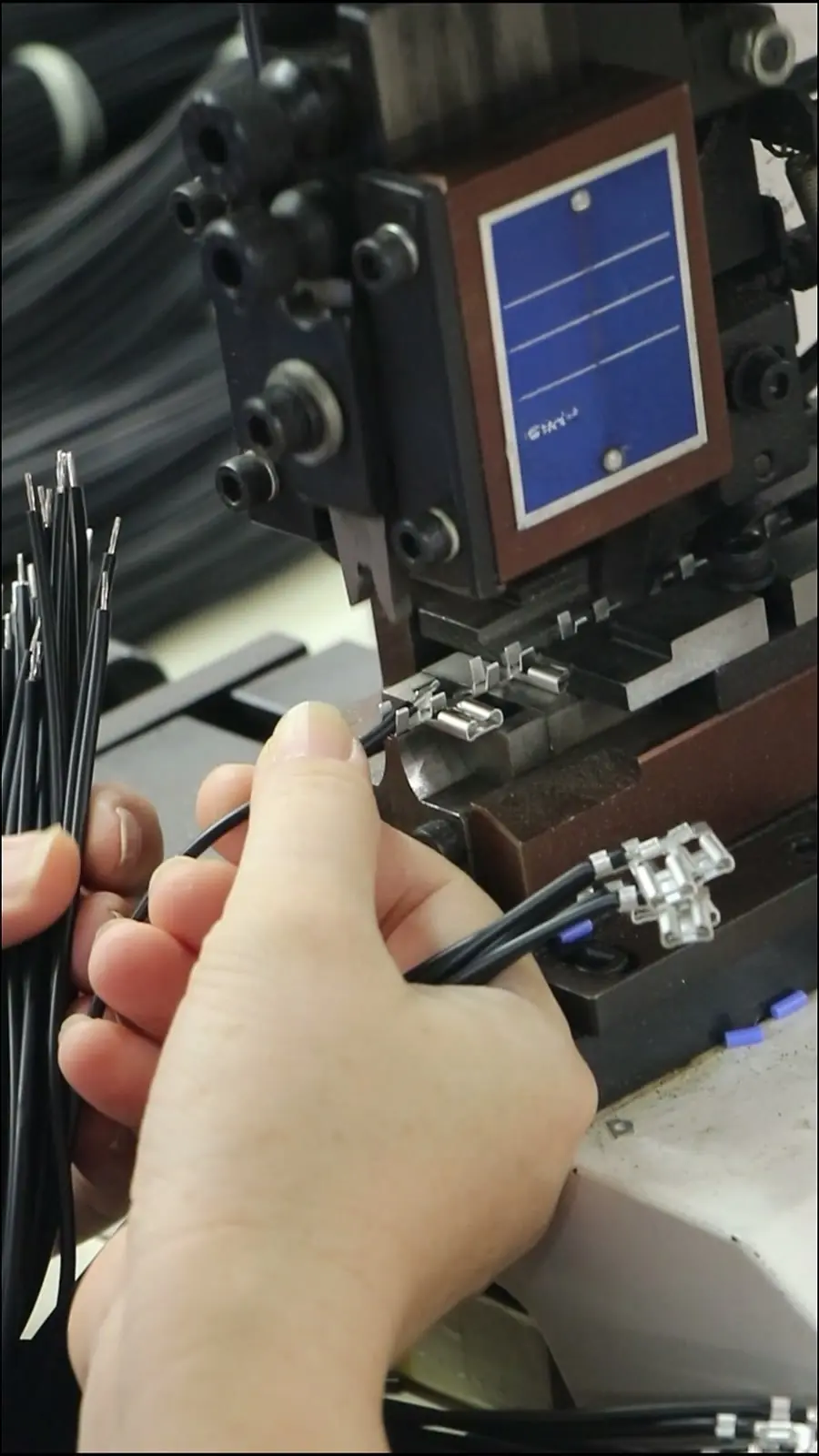
A correct terminal with the wrong crimp die can crack the barrel or under-compress the conductor, then pass a quick visual check while remaining mechanically weak. The terminal may hold during a casual tug but open later under harness flexing, vibration, or temperature change. That is why crimp approval cannot stop at appearance.
IPC/WHMA-A-620 defines acceptance criteria for conductor grip, insulation support, and pull-force retention in wire harness assemblies. Use that reference as the acceptance anchor, not a subjective “tug test.” For each new spade-terminal crimp, set a go/no-go inspection point on the line that checks crimp height, conductor brush, insulation support, and pull force against the terminal manufacturer’s tooling data.
For OEM procurement, require the wire harness manufacturing supplier to document tooling setup and pull-force results during first-article inspection before production approval. This documentation should cover the exact terminal, wire size, and crimp die combination used, so the production line does not drift into an unverified tooling setup later.
What Goes Wrong When Width Alone Is the Specification: Field Failure Modes
Field failures from spade-terminal mistakes share a common root cause: the BOM stopped at width. Consider a female quick-disconnect receptacle that loses retention after thermal cycling because the mating male tab is from a different thickness class. The parts measure the same width, but the spring geometry never reaches the designed contact force. Intermittent contact then appears under vibration, often after the harness has passed final inspection.
An insulation sleeve can hide incomplete insertion. The outer sleeve sits over the receptacle, the assembly looks fully seated, and no one has visibility into the actual spring engagement. The connection may pass continuity testing at rest, then fail when thermal expansion or harness motion separates the partially engaged surfaces. This type of fault is difficult to trace because it disappears when the technician probes the connector.
Plating choices create another hidden failure. Flash-gold terminals can corrode to high contact resistance after minimal mating cycles when the plating is specified without adequate thickness or a suitable underplate. Buyers who specify only the gold color without the plating package inherit a contact surface that is not built for repeated mechanical or environmental stress.
Crimp defects complete the pattern. The wrong crimp die cracks the barrel but passes a quick tug test, then opens under harness flexing or temperature changes. Each failure traces back to the same root cause: using width alone as the specification instead of locking down the full dimensional and mechanical family.
Make the BOM Confirmable: Minimum Fields for Your Next RFQ or Supplier PO
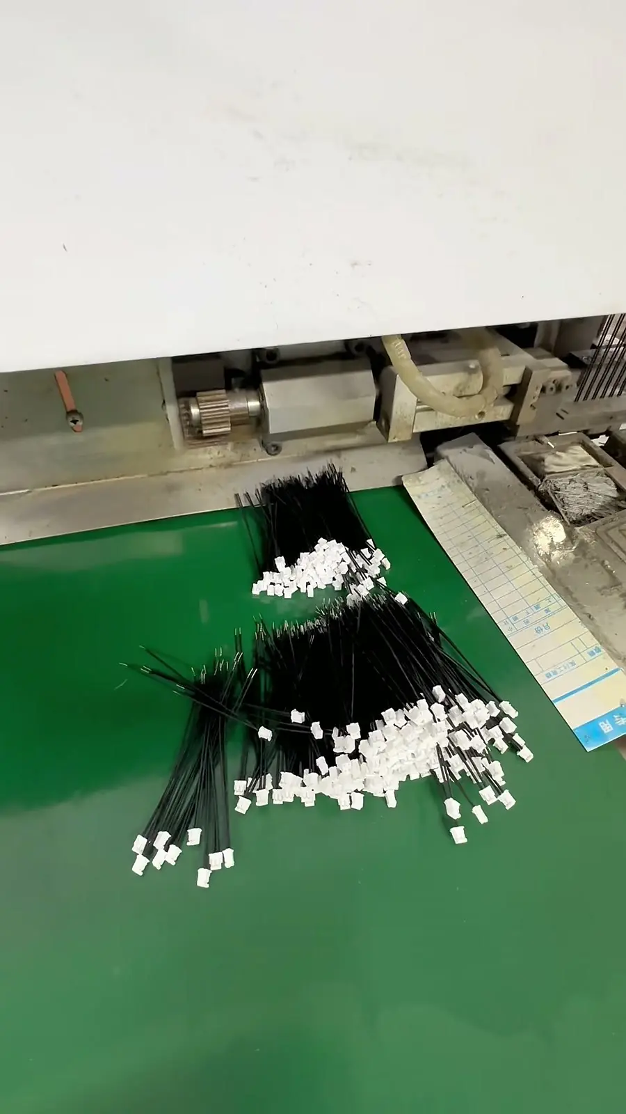
Every spade-terminal line should carry the same minimum fields before RFQ or PO release: terminal type, tab width, tab thickness, gender, insulation material, stud size where applicable, AWG range, plating, and mating part number. A line that reads “spade connector, 6.3 mm” contains only one of those fields and therefore has not completed the specification stage.
Require the supplier to confirm dimensional and retention compliance against IPC/WHMA-A-620 or UL 310 where relevant, instead of accepting a visual width check. For new harness programs, ask for a first-article sample with documented crimp height and pull-force results before series production. This sample should be built with the production-intent terminal, wire, seal or sleeve, and tooling so that the approval decision covers the same combination that will run on the line.
For OEM programs that need an external supplier to turn a confirmed BOM into production, support with requirement review, connector matching, sample coordination, production follow-up, inspection, and quality inspection and export packaging is available from suppliers such as EDOM Electronics. The key point is that the supplier should be able to work from the complete dimensional and retention data rather than a vague trade name.
Before releasing the next RFQ, run each terminal line through the decision table. If any line is missing a minimum field, it is not ready for quotation. The goal is to move an ambiguous “spade connector” BOM into a confirmable specification package that can be audited, sampled, and production-released.
Frequently Asked Questions
What is the difference between a spade connector and a blade terminal?
A blade terminal is one of the shapes hidden inside the loose term “spade connector.” It is a solid flat male tab that mates with a matching female quick-disconnect receptacle. A spade connector may also refer to a fork terminal with an open U-slot used under a screw or stud, so the two terms should not be treated as interchangeable without checking gender and mating form.
Can I use tab width alone to select a spade terminal?
No. Tab width is only one dimension in a mechanical family. Tab thickness, gender, spring retention angle, insulation material, locking feature, AWG range, and mating part number all affect whether the connection remains gas-tight and vibration-resistant. A terminal selected by width alone risks loose retention, incomplete insertion, or field failure.
Which insulation is better for a fork terminal in a hot engine area?
Nylon insulation is generally the safer choice for high-abrasion or engine-compartment applications because it provides higher heat performance and better mechanical resistance than vinyl insulation. Vinyl insulation remains a practical lower-cost option for general interior wiring, but the final choice should follow the harness routing and temperature profile.
How should crimp quality be verified for spade terminals?
Crimp quality should be checked against IPC/WHMA-A-620 acceptance criteria and the terminal manufacturer’s tooling data. Inspection points include crimp height, conductor brush, insulation support, and pull-force retention. A visual check or casual tug test is not enough for production release.
Should I request a first-article sample before production?
Yes. For a new spade-terminal harness program, request a first-article sample built with production-intent terminal, wire, insulation, and crimp die. The supplier should document crimp height and pull-force results so the approval covers the same combination that will run on the production line.
Key Takeaways
- The term “spade connector” is a family label, not a confirmed specification. It can refer to a fork terminal, a male blade terminal, or a female quick-disconnect receptacle.
- Tab width alone is not enough. Tab thickness, gender, insulation style, locking feature, AWG range, and mating part number must be stated on the BOM line.
- Use the Spade Connector Decision Table as a go/no-go gate. Any line with missing dimensional, insulation, or mating data should stop before quotation or sampling.
- Anchor crimp acceptance to IPC/WHMA-A-620 and manufacturer pull-force data, not a visual tug test.
- For OEM programs, require first-article samples with documented crimp height and pull-force results before series production release.
For specification review and connector matching on OEM harness or cable assembly programs, explore electronic connector sourcing support.