Direct Answer: The wire drawing process in wire harness manufacturing converts master copper rod (typically 8.0 mm ETP copper) into specified conductor gauges (AWG 10–32) by pulling it cold through sequential tungsten carbide and diamond dies. This plastic deformation increases tensile strength through work hardening, requiring controlled annealing to restore elongation (≥15–25% per ASTM B3) for crack-free terminal crimping. (See our guide on wire harness design principles for complete conductor sizing rules.) Understanding this process helps you ask the right questions about wire gauge, strand construction, and why quantity changes material pricing.
What a Wire Harness Actually Is (and the Components You’re Likely to See)
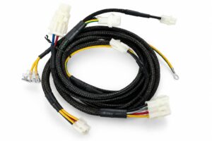
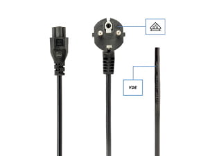
A wire harness is an organized bundle of conductors, terminals, connectors, protective sleeving, and labels that routes power or signals inside equipment. The term appears on drawings and BOMs in dozens of industries, but a harness is never just a few wires tied together with tape. It is a production-planned assembly: each wire is cut, stripped, crimped, routed, and dressed so it can be installed and serviced without confusion on the line.
The conductor in most harnesses is copper wire that has been drawn and annealed before insulation. Its final diameter, strand count, and elongation directly affect flexibility, current-carrying capacity, and how reliably it accepts a crimp terminal. Around that drawn conductor, a typical harness adds several layers of detail:
- Conductors: Solid or stranded copper wire, selected by gauge, insulation material, voltage rating, and temperature class.
- Terminals: Crimp contacts or lugs attached to stripped wire ends, matched to the conductor size and connector cavity.
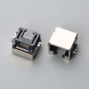
- Connectors: Housings, headers, or PCB connectors that mate the harness to the equipment.
- Protective sleeving: Loom, split tubing, braided sleeving, or tape that bundles and protects routed wires inside the enclosure.
- Labels: Wire numbers, destination codes, harness tags, or barcode labels that identify branches and simplify installation and field service.
For acceptance of the finished assembly, IPC/WHMA-A-620[1] defines three workmanship classes with increasing inspection and documentation requirements. Even at the drawing stage, knowing which class is expected helps avoid quoting a harness that is over-built or under-inspected for the application.
Wire Harness vs. Cable Assembly: The Most Common First-Time Confusion
Many first-time buyers use the terms wire harness and cable assembly interchangeably. On a drawing, the difference changes what the supplier must quote. A wire harness typically uses sleeving, loom, or tape and is installed inside equipment where it is protected from direct moisture, abrasion, and repeated flexing. A cable assembly has a heavy outer jacket and is built for exposed runs, harsh environments, or machine-to-machine connections.
| Characteristic | Wire Harness | Cable Assembly |
|---|---|---|
| Primary construction | Bundle of individual conductors with terminals, routed inside loom or tape | Multiple conductors inside a continuous outer jacket, often with molded connectors |
| Typical installation environment | Inside equipment, panels, enclosures | Exposed runs, harsh conditions, outdoor or machine-to-machine links |
| Mechanical protection | Loom, split sleeve, tape, conduit | Heavy-duty jacket, shielding, optional armor |
| Moisture and abrasion resistance | Lower unless specified | Higher by design |
| Termination complexity | Many individual wire breakouts into multiple connectors | Fewer breakouts, more standardized cable ends |
| Drawing/BOM implication | Branch lengths, routing, labels, exact wire lengths | Jacket material, outer diameter, bending radius, sealing, environmental ratings |
Before contacting a supplier, confirm which assembly type the drawing actually shows. If the drawing calls for an outer jacket and environmental sealing rather than internal loom, the buyer may need to specify jacketing material for a custom cable assembly instead. Treating a harness as a cable assembly, or vice versa, is one of the fastest ways to receive an unbuildable quote.
If the drawing is unclear, request a quick type review before formal quoting. Send the drawing for a preliminary wire harness or cable assembly check.
Why Wire Harness Quotes Need More Upfront Information Than Buyers Expect
In our experience, the first inquiry from a new buyer almost always arrives without a quantity. Without that one number, we can’t give a meaningful price — material costs shift significantly between 50 units and 500. The reason is not supplier slowness; the inquiry itself is not ready for material evaluation.
Quantity affects drawn copper wire and connector pricing because both carry minimum-order-quantity tiers and volume-sensitive unit costs. A buyer who only needs 50 prototype assemblies is evaluating a different material plan than a buyer placing four releases of 500 per year. Without an annual usage or per-release quantity, the supplier cannot determine whether the harness should be quoted as a small-batch prototype or a repeat production job.
Wire specification must be exact as well. Gauge, solid or stranded construction, insulation material, voltage rating, and temperature class are not interchangeable. A UL 758[2] AWM wire style, for example, identifies a specific insulation and use condition rather than a generic hook-up wire. If the drawing says only “wire, 20 AWG,” the supplier still needs the insulation system, UL style or equivalent, and any oil, flame, or temperature requirements before selecting the correct drawn copper conductor.
Connector platingas discussed in our Electrical Harness Design: Key Considerations for OEM Procurement guide must also be specified. Tin, gold, and selective gold plating change both cost and long-term reliability. A tin-plated terminal is cost-effective for static internal harness runs with contact normal forces above 100g, whereas selective gold plating (typically 15–30 µin) is mandatory for low-level signal circuits subject to fretting corrosion or repeated mating cycles. To balance NRE and connector MOQ constraints during RFQ evaluation, EDOM provides DFM reviews to verify whether alternate commercial equivalents or tin-lead/gold selective platings can meet field durability targets without inflating sample lead times.
Finally, wire color is a hidden cost driver. Standard solid colors can often be produced from readily available stock, while custom wire colors, stripes, or tracer codes add setup time and minimum-run constraints. If the application allows standard color coding, saying so early can shorten lead time and reduce cost without changing performance.
What Is the Wire Drawing Process in Wire Harness Manufacturing?
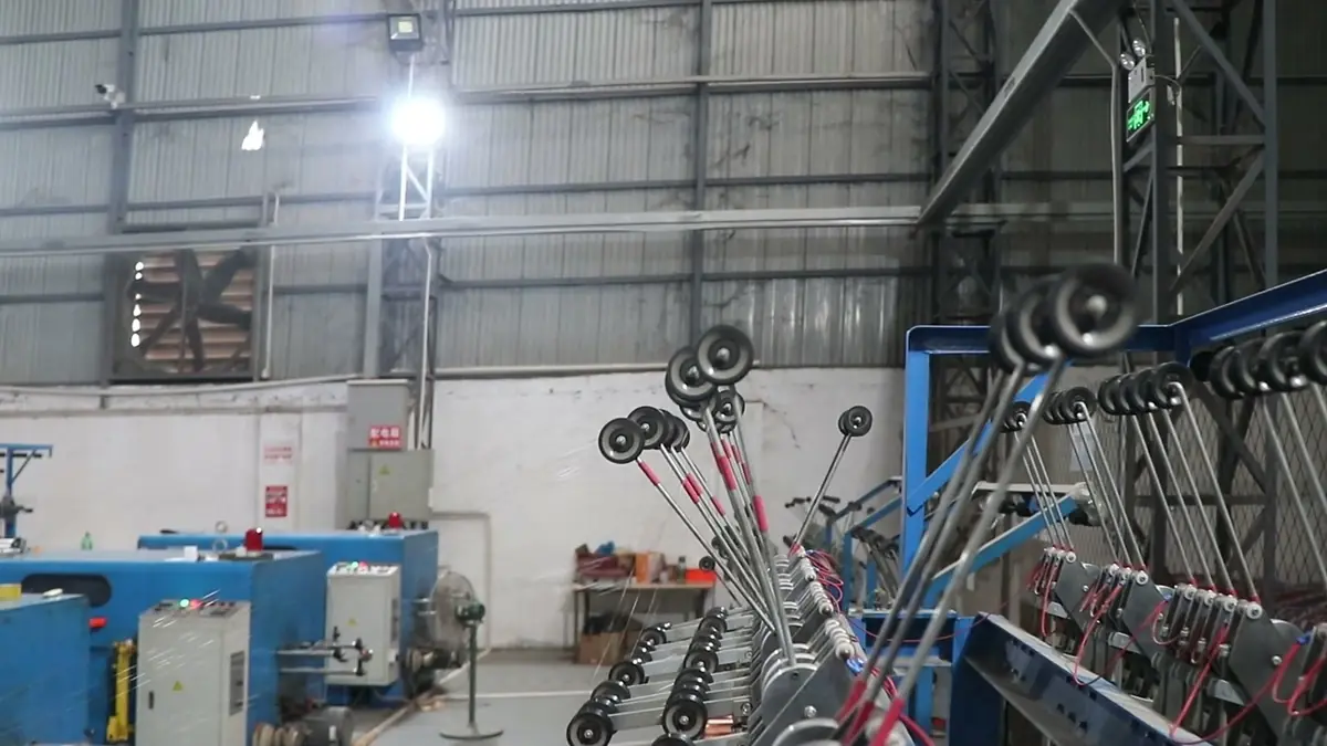
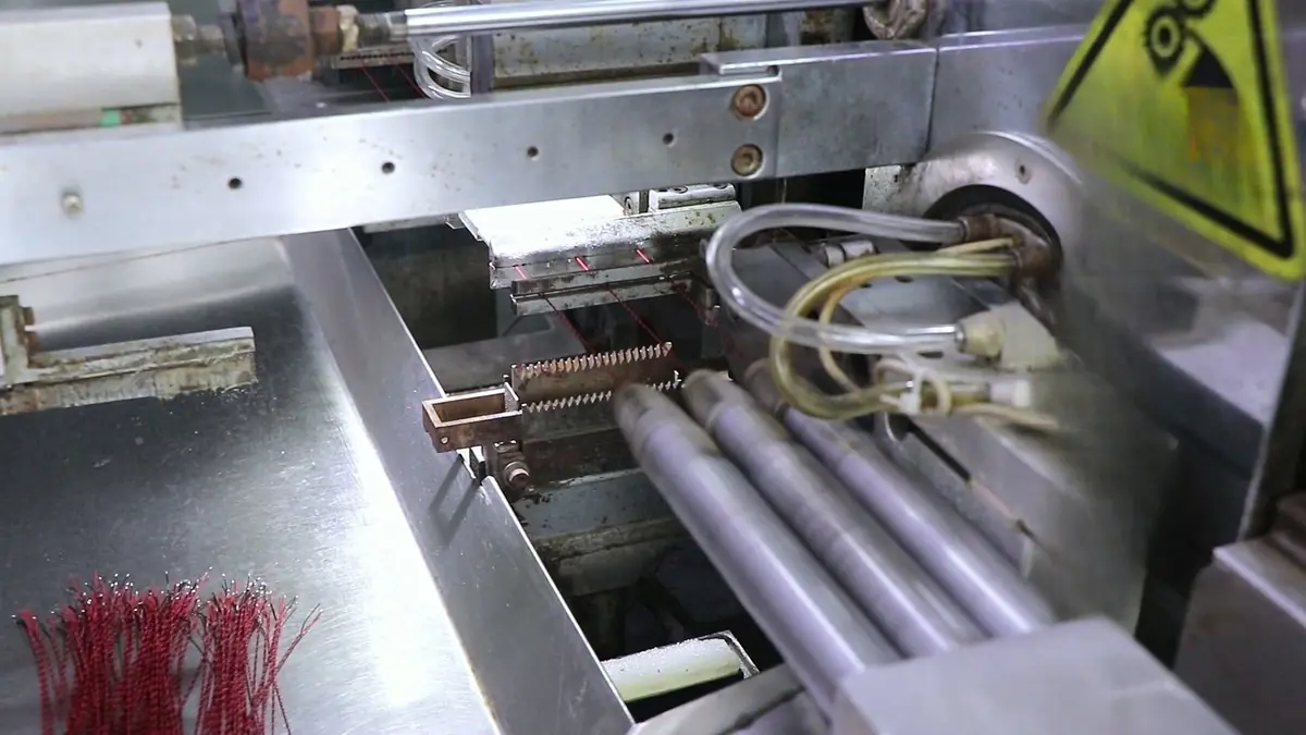
Wire drawing is the process that turns copper rod into the fine conductor used inside a wire harness. In simple terms, copper rod is pulled through a drawing die, a hard tool with a tapered bore, to reduce its diameter. The process is repeated through a series of progressively smaller dies until the copper reaches the required gauge.
The die material changes with the reduction stage. Tungsten carbide is common for initial rod breakdown and intermediate passes because it resists abrasive wear at larger diameters. For fine final passes where diameter tolerance and surface finish are tighter, a diamond die is often used. The diamond die holds a more precise bore and produces the uniform copper wire diameter needed for stable crimp heights and connector insertion later in the harness process.
Every cold-drawing pass induces severe strain hardening in the copper crystals (typically starting from 8.0 mm ETP copper rod, ASTM B49). This boosts tensile strength up to 400+ MPa while collapsing elongation to under 2%. Without in-line continuous resistance annealing (heating the wire in a protective steam or nitrogen atmosphere at 450–500°C), the conductor becomes brittle. Controlled recrystallization restores elongation to ASTM B3 standards (typically 15% to 30% depending on wire diameter) and conductivity (≥100% IACS), ensuring the core does not shear during high-speed stripping or terminal crimping.
| Drawing Stage | Tool/Die Material | Main Effect on Copper Wire | Harness Relevance |
|---|---|---|---|
| Initial rod breakdown | Tungsten carbide | Large diameter reduction; grain structure begins to align | Sets the available conductor gauge range and base material cost |
| Intermediate passes | Tungsten carbide | Further reduction; tensile strength increases through work hardening | Affects conductor handling during stranding and insulation |
| Final fine passes | Diamond die (PCD/Natural) | Sets precise bare conductor OD tolerance (±0.001 mm); high cold-work state | Calibrates baseline cross-sectional area (CMA) critical for terminal crimp height calculations |
| Annealing after drawing | Controlled furnace | Restores ductility and elongation; softens work-hardened copper | Prevents conductor breakage during flexing, stripping, and crimping |
Buyers do not need to specify die materials themselves. However, understanding that drawn copper wire has a defined tensile strength and elongation before insulation helps explain why a supplier cannot simply substitute “any 20 AWG wire” into a harness quote. The drawn and annealed condition of the copper influences flexibility, crimp quality, and long-term conductor performance.
The Exact Information a Supplier Needs to Quote Accurately
Preparing this information before the first inquiry reduces back-and-forth and makes the RFQ easier for a supplier to evaluate quickly. The checklist below outlines the minimum data set for a wire harness drawing or BOM.
| Category | What to Provide | Why It Matters |
|---|---|---|
| Quantity | Annual usage, per-release quantity, target order frequency | Copper and connector pricing is volume-tiered; setup and tooling amortization depend on batch size |
| Wire gauge and conductor construction | AWG or metric size, solid or stranded, strand count, insulation material, voltage/temperature rating | Determines drawn wire diameter, flexibility, current capacity, and UL style compatibility |
| Connector part numbers or datasheet references | Manufacturer part number, pitch, plating specification, circuit count | Connector matching, crimp tooling, and plating selection affect cost, lead time, and reliability |
| Color requirements | Standard solid colors or custom printing/striping/tracer codes | Custom color setups add lead time and minimum run constraints |
| Test requirements | Continuity, appearance inspection, pull-force, hipot, or other final verification | Defines the inspection endpoint and documentation package |
How Conductor Drawing Tolerances Drive Crimp Integrity
Terminal crimp tool validation relies on strict conductor cross-sectional area consistency. The table below demonstrates how drawing-stage variance propagates into end-of-line manufacturing defects:
| Conductor Drawing Defect | Physical Root Cause | Assembly Line Failure Mode | IPC/WHMA-A-620 Acceptance Risk |
|---|---|---|---|
| Diameter undersize (> -1.5% CMA) | Over-worn diamond die profile | Loose crimp compaction; low pull-off force | Fails Section 19.7 (Tensile Test Failure) |
| Under-annealing (Elongation < 15%) | Annealer voltage drop or line speed surge | Core strand fracture under crimp wing deformation | Fails Section 19.5 (Severed/Cracked Strands) |
| Surface oxidation / drawing oil residual | Exhausted capstan emulsion or cooling delay | High contact resistance; poor solder wetting / ultrasonic bonding voids | Fails Section 19.6 (Open/Intermittent Resistance) |
If connectors are included, the most useful input is a complete manufacturer part number or a clear datasheet. A generic description such as “2-pin connector” is rarely enough because pitch, keying, terminal series, and plating all vary. For RoHS-aligned projects, ask for RoHS-compliant terminal and housing options rather than assuming all stock is identical.
How Wire Harnesses Are Manufactured: From Drawn Wire to Finished Assembly
The drawn copper wire is only the first manufacturing step. After the conductor is prepared, the production floor moves through a sequence of cutting, termination, routing, and inspection steps. A brief process view helps buyers understand why a quote cannot be finalized from a partial drawing.
- Inspect incoming copper rod for diameter, surface condition, and material consistency before drawing.
- Pull the rod through a series of drawing dies to reduce diameter, using tungsten carbide for intermediate passes and a diamond die for fine final reduction.
- Anneal the work-hardened copper wire to restore ductility and elongation, then verify tensile strength and elongation before stranding or insulation.
- Strand multiple drawn wires if the specification requires a stranded conductor, or use a solid conductor as specified.
- Apply insulation material such as PVC, XLPE, or fluoropolymer according to the voltage and temperature class on the drawing.
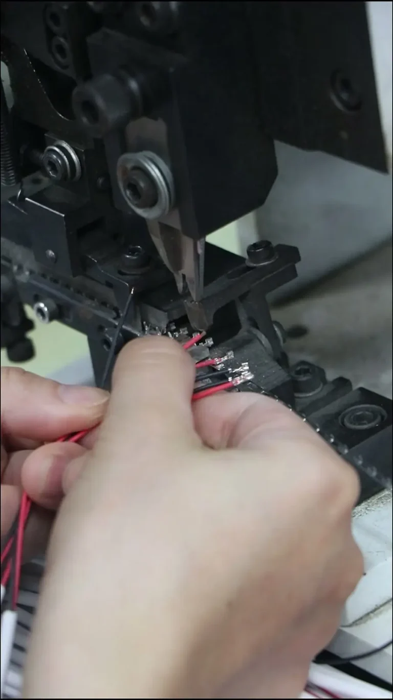
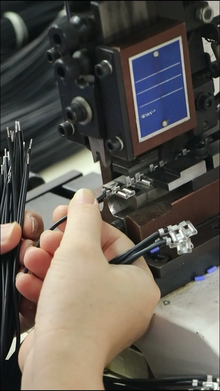
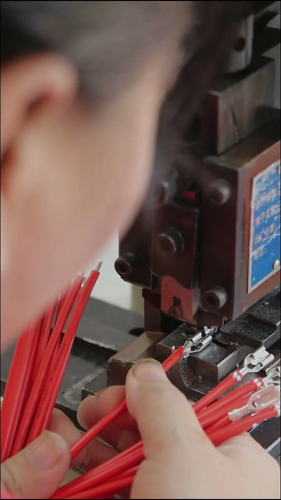
- Cut wires to length, strip insulation, and crimp terminals using the correct tooling and die set for the connector series.
- Insert terminals into connector housings; route wires through loom, sleeving, or conduit; and apply labels or destination markers.
- Perform continuity testing, appearance inspection, and customer-specified checks such as pull-force or hipot verification. For more detail on final verification, review quality inspection and export packaging procedures.
- Prepare export-ready packaging, including collation, labeling, carton marking, and protective wrapping for shipment.
Wire drawing is the earliest quality step in this sequence. Diameter variation or insufficient elongation at the conductor stage shows up later as crimp problems, erratic continuity, or conductor breakage during installation. That is why a production-coordinated supplier will treat the drawn copper specification as part of the RFQ review, not as an afterthought.
After understanding the drawn wire foundation, reviewing the full production routing from cutting to export packagingas outlined in our Custom Wiring Harness Manufacturing for OEM Equipment | EDOM Electronics article can help a buyer prepare a more reliable RFQ. Explore the complete wire harness manufacturing process and OEM support workflow.
Frequently Asked Questions
Is wire drawing the same as wire extrusion?
No. Wire drawing reduces the diameter of copper rod through a series of drawing dies before any insulation is applied. Wire extrusion is a separate later step that applies molten or thermoplastic insulation around the drawn conductor. Both are part of the overall wire-making sequence, but they control different parameters.
Why does quantity change wire harness pricing so much?
Drawn copper wire and connector materials are purchased in volume tiers. Small prototype quantities carry a different material and setup cost structure than repeat production releases. Without an annual usage or per-release quantity, a supplier cannot determine the correct material plan or amortize tooling and setup time accordingly.
What is the difference between solid and stranded conductors in a wire harness?
A solid conductor is a single drawn copper wire. A stranded conductor is made from multiple smaller drawn wires twisted together. Stranded conductors are more flexible and tolerate repeated bending during installation, while solid conductors may be used where the wire will remain stationary and a more rigid routing is acceptable.
Does annealing affect how well a wire harness can be crimped?
Yes. Drawing hardens the copper and reduces elongation. If the wire were not annealed, it would be brittle and could crack during stripping, crimping, or flexing. Annealing restores ductility and elongation, giving the conductor enough softness to form a stable crimp without conductor breakage.
Can a supplier review an incomplete wire harness drawing before quoting?
In most cases, yes. A production-coordinated supplier can perform a drawing and BOM review, identify missing connector types or wire callouts, and confirm what additional details are needed before a final quote. In most cases, yes. A production-coordinated supplier can perform an upfront DFM review to identify missing connector series, verify plating compatibility, and cross-reference wire callouts against IPC/WHMA-A-620 standards to finalize the quotation.
Key Takeaways
- A wire harness is a routed, labeled, and terminated bundle of drawn copper conductors, connectors, sleeving, and markings — not just a few wires tied together.
- The wire drawing process reduces copper rod through tungsten carbide and diamond dies, increasing tensile strength through work hardening before annealing restores ductility and elongation.
- Wire harness quotes require more upfront detail than many first-time buyers expect: quantity, wire construction, connector plating, color requirements, and test criteria all change cost and lead time.
- Preparing an accurate RFQ before contacting a supplier reduces quoting delays and helps avoid wrong assumptions about harness versus cable assembly construction.
- The drawn wire specification is the earliest quality input in harness manufacturing; diameter, elongation, and tensile strength affect crimp quality and long-term conductor reliability.