What the Wire Bonding Process Actually Is
Wire bonding is not soldering. There is no solder paste, no reflow profile, and no cleaning flux. Instead, a fine metal wire is pressed against a bond pad under controlled force while ultrasonic energy—and sometimes heat—is applied. The combination creates a metallurgical intermetallic compound between the wire and the pad surface. That intermetallic layer, not a bulk solder fillet, carries both the electrical and mechanical connection.
The process splits into two main families. Ball bonding uses a ceramic capillary tool and Electric Flame-Off (EFO) discharge to form a Free-Air Ball (FAB) on a die pad using thermosonic bonding energy (typically 150°C to 220°C), primarily with gold or copper wire on an aluminum pad. Wedge bonding uses a wedge tool to press wire or ribbon directly onto the pad: heavy aluminum wire is typically bonded using pure ultrasonic energy at ambient temperature, whereas gold wire or ribbon wedge bonding requires thermosonic heating. Each family behaves differently in speed, loop profile, and pad metallization compatibility.
Wire material is also a critical engineering trade-off. Gold wire (Au) is the most forgiving because it resists oxidation and forms predictable intermetallic growth with aluminum pads. Copper wire (Cu) lowers material cost and improves electrical/thermal conductivity, but its higher hardness increases pad cratering risk and requires shielding gas (typically 95% N₂ / 5% H₂ forming gas) or palladium-coated copper (PCC) wire during EFO ball formation to prevent oxidation. Aluminum wire (Al) is typically wedge-bonded onto aluminum pads in power modules, maintaining a monometallic system that eliminates gold–aluminum intermetallic degradation.
The bond pad metallization and cleanliness are not secondary. Oxide layers, organic residues, or thin plating prevent reliable intermetallic formation even when the bonding parameters look correct. A first article can pass on freshly cleaned substrates with a warmed capillary, while the production lot runs oxidized pads and shows non-stick bonds or lifted balls.
Ball Bonding vs. Wedge Bonding: The First Specification Fork
When a drawing simply calls out “wire bonding” without a method, wire material, or pad finish, the process is undefined. The first decision point is whether the application needs ball bonding or wedge bonding. That single choice changes the tool, the wire type, the loop height, the throughput, and the failure modes that must be controlled.
| Parameter / Feature | Thermosonic Ball Bonding | Ultrasonic / Thermosonic Wedge Bonding |
|---|---|---|
| Wire Material & Size | Gold (Au), Copper (Cu), Pd-Cu, Silver (Ag); typically 15–50 μm (0.6–2.0 mil) diameter | Aluminum (Al) fine/heavy wire or ribbon; Au wire/ribbon; 25 μm up to 500 μm (1–20 mil) |
| Typical Pad Finish | Aluminum (Al-Si-Cu) or Ni/Pd/Au (ENEPIG) | Aluminum, Gold, or Ag-sintered power substrates |
| Tool & Alignment | Ceramic capillary; omnidirectional (360° wire exit after 1st bond) | Tungsten carbide or titanium wedge; unidirectional (requires rotating table aligner) |
| Process Temperature | 150°C – 240°C (Thermosonic) | Ambient (25°C) for Al ultrasonic; 150°C – 220°C for Au thermosonic |
| Throughput (Speed) | High (10–25+ wires/sec) | Moderate to Slower (2–6 wires/sec due to rotational alignment) |
| Loop Height & Fine Pitch | Higher loop (100–250 μm); supports ultra-fine inline pad pitch (< 40 μm) | Low, flat loop profile (50–120 μm); tighter deep-access reach |
| Common Applications | BGA/QFN packages, Chip-on-Board (COB) sensors, LEDs, logic/memory ICs | IGBT/SiC power modules, automotive battery interconnects, RF/microwave hybrids, MEMS |
When a module assembly drawing calls out die-level wire bonding alongside board-level cable exits without defining encapsulation clearance or connector mating forces, mechanical stress from the harness can easily fracture adjacent bond regions. EDOM’s B2B engineering team helps OEMs review the board-to-cable transition, matching low-insertion-force connectors and strain-relief overmolding so external wire harnesses never compromise delicate on-board semiconductor interconnects.
Step-by-Step Wire Bonding Process: From Prepared Pad to Verified Bond
A repeatable wire bonding process follows a defined sequence. Buyers should use these steps to audit a contract manufacturer’s claim, not just confirm that a first-article sample exists.
- Step 1 — Substrate preparation / plasma cleaning: Bond pads are cleaned to remove oxides and organic contamination before bonding. Incoming inspection confirms pad metallization, surface finish, and cleanliness.
- Step 2 — First bond: On a ball bonder, the capillary forms a free-air ball on the die pad with thermosonic energy. On a wedge bonder, the wedge tool presses the wire onto the first pad with ultrasonic energy.
- Step 3 — Loop formation: Tool path, wire stiffness, and tension define loop height and shape. The loop profile matters for clearance to adjacent pads, shorting risk, and wire sweep under encapsulation mold flow.
- Step 4 — Second bond: The wire is stitched or crescent-bonded to the package lead or substrate pad, usually at lower force and power than the first bond to reduce pad damage.
- Step 5 — Tail break and tail length control: After the second bond, the wire breaks to leave a consistent tail that forms the next ball. Inconsistent tails cause missed balls, machine stops, and yield loss.
- Step 6 — Pull and shear verification: Destructive or non-destructive bond pull testing and ball shear testing on the specified sample size confirm intermetallic formation and pad adhesion. For high-reliability or defense applications, anchor wire pull strength to MIL-STD-883 Method 2011 and ball shear strength to JEDEC JESD22-B116 (or AEC-Q006 for automotive copper wire interconnects).
What Goes Wrong in the Field: Failure Modes That Start at the Bond
Field failures rarely appear as “bad wire.” They appear as intermittent opens, thermal drift, or mechanical damage. Most can be traced to a specific process parameter or contamination source.
| Failure Signature | Typical Root Cause | Process or Design Control to Specify |
|---|---|---|
| Non-stick | Insufficient ultrasonic energy, force, or pad contamination prevents intermetallic formation | Verify cleaning protocol, pad oxidation limits, and bonding parameter windows |
| Lifted balls | Weak intermetallic growth from low temperature/energy, thin pad metallization, or contaminated pads | Require pull/shear testing on production-condition samples, not just first articles |
| Cratering | Excessive force or ultrasonic energy on thin or brittle pad structures damages the pad or underlying dielectric | Review pad thickness and the underlying stack-up before approving bond parameters |
| Wire sweep | High loop profile and small wire diameter deflect wires under encapsulation mold flow | Set a maximum loop height and wire geometry as design parameters |
| Intermetallic degradation & Kirkendall voiding | Asymmetric atomic diffusion in Au–Al bonds above 150°C forms brittle intermetallic phases (e.g., Au₅Al₂ and AuAl₂ “purple plague”) and Kirkendall voids; Cu–Al bonds suffer galvanic corrosion catalyzed by halide/chlorine ions in molding compounds under bias-humidity stress | Specify green (low-halide < 20 ppm) epoxy molding compounds (EMC), enforce High-Temperature Storage Life (HTSL per JESD22-A103) and HAST qualification, or use monometallic Al–Al systems for high-temperature power cycling |
What to Specify Before You Approve a Supplier or Accept a Quote
Approving a wire bonding supplier without fixing the following variables is the fastest way to turn a polished sample into a field reliability problem. Each item should appear in the drawing notes, the purchase specification, or the first-article inspection plan.
- Wire material and diameter: Gold, copper, or aluminum. Wire diameter affects current capacity, loop stiffness, bond force, and cost.
- Pad metallization and plating stack-up: Specify die pad thickness (typically ≥ 0.8–1.2 μm Al) and substrate plating standards—such as IPC-4556 (ENEPIG) for mixed Au/Cu wire bonding or wire-bondable soft gold over nickel—alongside surface roughness and incoming ionic cleanliness limits.
- Bonding method and energy mode: Ball versus wedge, thermosonic versus ultrasonic, and manual, semi-automated, or fully automated bonding.
- Loop height and profile: Set a maximum loop height and define whether a low-loop or high-loop profile is required for clearance and encapsulation.
- Pull force and ball shear acceptance criteria: Anchor wire pull testing to MIL-STD-883 Method 2011 and ball shear testing to JESD22-B116. Define minimum gram-force (gf) thresholds by wire diameter, acceptable fracture modes (e.g., wire break at neck vs. rejected bond lift/cratering), sample sizes, and Cpk requirements (typically Cpk ≥ 1.67).
- Cleanliness protocol and storage: Plasma cleaning, maximum time between clean and bond, nitrogen storage for oxidation-prone wires, and pad inspection method.
- Sampling plan: First-article, in-process, and final lot sampling. Specify whether a first article can be built by a senior operator on freshly cleaned substrates or must be built under production conditions.
From Wire Bond Approval to the Interconnects Around It
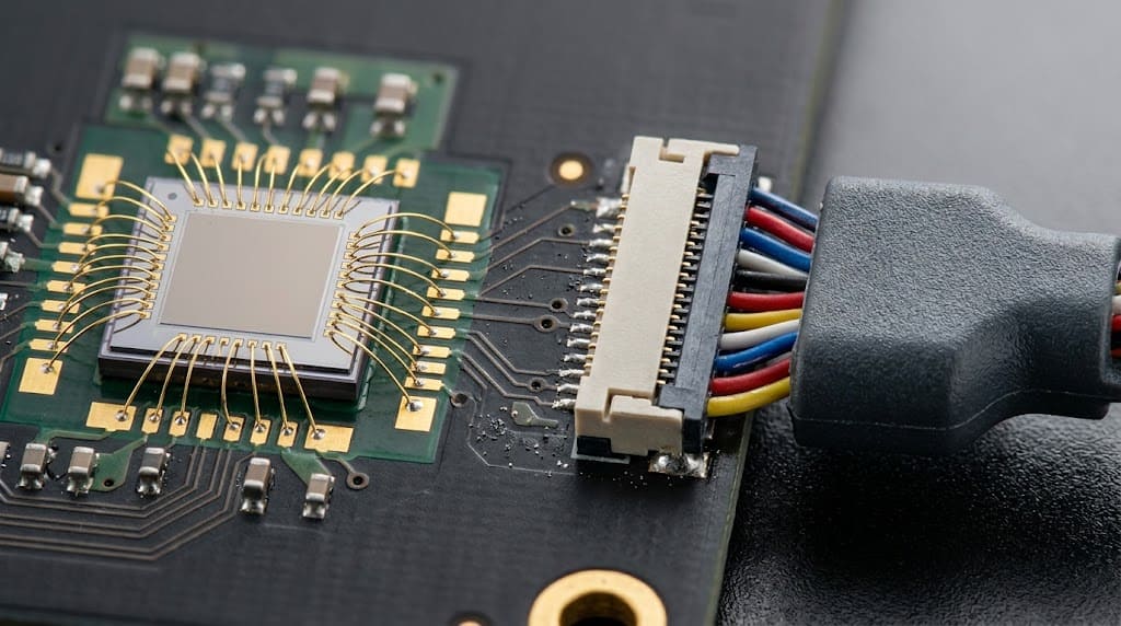
Wire bonding sits inside a larger assembly. The same module may also need board-to-board connectors, custom cable assemblies, wire harnesses, potting, and export-ready packaging. An OEM buyer should review the entire interconnect path beyond the die: pad-to-package, package-to-board, board-to-cable, and cable-to-system. The same drawing-to-inspection logic applies outside the module, including quality inspection and export packaging for the finished assembly.
Frequently Asked Questions
What is the difference between wire bonding and soldering?
Wire bonding is a solid-state micro-welding process that uses ultrasonic or thermosonic energy plus force to form an intermetallic compound between a fine wire and a bond pad. Soldering uses a molten filler alloy and flux to create a bulk fillet. Wire bonding is used for semiconductor die and chip interconnects; soldering is typically used for component-to-board assembly.
Which wire material should be used for wire bonding?
Gold wire is the most forgiving for ball bonding on aluminum pads because it resists oxidation and forms consistent intermetallic growth. Copper wire lowers cost but is harder and oxidation-sensitive. Aluminum wire is usually wedge-bonded onto thick aluminum pads for power modules and RF applications. The choice must match the pad metallization and the reliability environment.
Why does a wire bond pass first article but fail in volume?
A first article is often built by a senior operator on freshly cleaned substrates with a stabilized capillary. Production lots may run oxidized pads, older tooling, or less consistent cleaning. If pull and shear test thresholds are not specified and sampled under production conditions, the process cannot be separated from a controlled demonstration.
What tests should be specified for wire bond acceptance?
For high-reliability applications, specify pull testing and ball shear testing anchored to MIL-STD-883 Method 2011. The specification should include minimum force values, acceptable failure modes, sample sizes, and pass/fail rules for first-article, in-process, and final lot samples.
Does EDOM provide wire bonding services?
EDOM supports OEM buyers with requirement review, drawing clarification, connector matching, production follow-up, inspection, and export-ready packaging for cable assemblies and wire harnesses. Wire bonding itself is typically qualified directly with the semiconductor assembler or bond house. For the surrounding cable and harness interconnects, EDOM’s team can support the sourcing and production release process.
Key Takeaways
- Wire bonding is a solid-state micro-welding family, not a single standardized heat-attach step. Ball bonding and wedge bonding create very different loop profiles, pad requirements, and failure risks.
- Pad metallization and cleanliness control intermetallic formation. A polished first article on cleaned substrates does not prove a stable high-yield production process.
- Wire material, loop height, pull force, shear force, and sampling criteria must be specified before accepting a quote or approving a supplier.
- Failure modes—non-stick, lifted balls, cratering, wire sweep, and intermetallic growth—each trace back to controllable process parameters or contamination sources.
- The wire bond is only one link in the interconnect path. The same drawing-to-inspection discipline should extend to cable assemblies, wire harnesses, and export packaging.
If the same design also requires cable assemblies or wire harness interconnects, explore wire harness OEM services to extend the same process discipline beyond the module.