2026年10月7日
How CAN Bus Connectors Work: Types, Pinouts, and Wiring Basics
Learn how CAN bus connectors work, including types, pinouts, and wiring basics. Read this guide to choose the...

Rapid Prototyping in 3-5 Days
B2B Electronic Connection Solution
Factory-backed connector sourcing and electric connection support for OEMs, distributors and electronic equipment manufacturers.
OEM Ready
Factory Supply
Fast Quote
Product Specifications
Key parameters for OEM, distributor and engineering evaluation.
Detailed Product Information
Structured parameters, material notes, application context and frequently asked questions for engineering and procurement evaluation.
Drop-in Replacement: This part is a direct, pin-compatible substitute for the competitor part number listed above. No design modification required.
| Material | Value / Description |
|---|---|
| Housing Material | High-Temperature Thermoplastic LCP, UL94V-0, Beige |
| Contact Material | Phosphor Bronze |
| Contact Plating | Gold Flash Overall; 15 µin Min. Gold on Contact Area |
| Shell / Retention Material | Not Applicable (Unshielded Insulator Design) |
| Packaging Material | Standard Embossed Carrier Tape & Reel |
| Characteristic | Value |
|---|---|
| Operating Temperature Range | High-Temperature Reflow Compatible (Exact °C Range Not Specified on Drawing) |
| General Linear Tolerances | .X = ±0.25 mm; .XX = ±0.20 mm; .XXX = ±0.10 mm |
| Angular Tolerance | ±1° |
Industrial Automation Controllers, PLCs, and Embedded Single Board Computers (SBCs)
High-Speed Data Acquisition Modules and Telecommunications Mezzanine Cards
Medical Diagnostic Imaging and Patient Monitoring Circuit Boards
Automotive Infotainment, ADAS Control Units, and Telematics Systems
Smart Metering, Test & Measurement Instruments, and Industrial HMI Displays
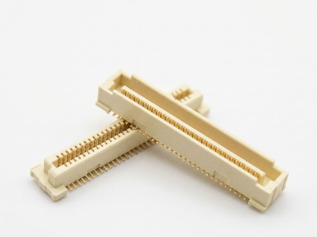
This 0.80mm pitch Board-to-Board (BTB) vertical surface-mount receptacle is engineered for high-density mezzanine PCB interconnections. Featuring a compact 3.70mm profile height and available in 40, 50, 60, 80, 100, 120, 140, 160, 180, and 200 contact configurations, it delivers reliable high-speed signal and power transmission across compact electronic assemblies. Constructed with a beige UL94V-0 high-temperature LCP thermoplastic insulator and phosphor bronze terminals with 15 µin minimum gold plating on the contact area, this surface-mount socket withstands lead-free SMT reflow soldering processes while maintaining low contact resistance and superior corrosion resistance.
For optimal surface-mount solderability and mechanical retention, the recommended PCB land pattern requires 0.50mm ±0.03mm wide by 2.00mm ±0.05mm long copper pads spaced at a 0.80mm ±0.03mm pitch, maintaining a 6.40mm ±0.05mm outer span across rows and a 2.50mm ±0.03mm inner clearance. Asymmetric polarization mounting holes must be drilled at Ø0.80mm ±0.05mm and Ø1.20mm ±0.05mm to match the connector’s 0.70mm and 1.10mm locating bosses (with a 0.75mm ±0.15mm peg standoff length). Strict 0.10mm maximum terminal coplanarity is maintained across all pin counts from 40 to 200 positions to prevent open solder joints during automated reflow.
2026年10月7日
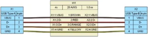
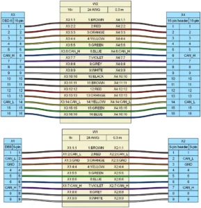
Learn how CAN bus connectors work, including types, pinouts, and wiring basics. Read this guide to choose the...
2026年9月12日
How to verify connector compatibility beyond pin count with 5 checks covering termination, plating, geometry, tooling, and ratings....
2020年7月10日
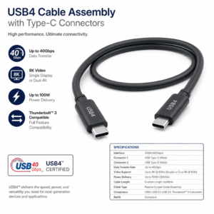
Are you confused by USB4 marketing claims when selecting cables for your products? You’re not alone—we’ve received dozens...
2026年9月27日
What are the different types of USB connectors? Compare USB Type-A, Type-B, Type-C, Mini-B, and Micro-B to source...
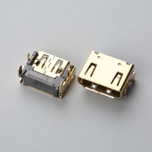
Overview The HDMI Type A 19-Pin Female Receptacle SMT Connector is a precision-engineered, high-speed digital interface designed for...
View ProductOverview The HDMI Type A 19-Pin Female Receptacle Short Body SMT Connector with Flange is an industrial-grade interconnect...
View ProductPin socket connectors, also known as female header connectors, are electrical connectors used to mate with pin header...
View ProductThe Reverse Sinking Mount (Mid-Mount) DC Power Jack Female Connector features an ultra-low profile height of 1.60mm combined...
View ProductProduct Document
Use this document for internal review, engineering comparison, and RFQ preparation.
We support importers, distributors, and electronics manufacturers with product matching, alternative sourcing, assembly integration, and factory-direct production coordination.